Download presentation
Presentation is loading. Please wait.

1
Chapter 6: Memory Memory is organized into a hierarchy
Memory near the top of the hierarchy is faster, but also more expensive, so we have less of it in the computer – this presents a challenge how do we make use of faster memory without having to go down the hierarchy to slower memory? CPU accesses memory at least once per fetch-execute cycle: Instruction fetch Possible operand reads Possible operand write RAM is much slower than the CPU, so we need a compromise: Cache We will explore memory here RAM, ROM, Cache, Virtual Memory The access time values shown in this figure are a bit out of date but will suffice for this chapter.

2
Types of Memory Cache RAM ROM
SRAM (static RAM) made up of flip-flops (like Registers) Slower than registers because of added circuits to find the proper cache location, but much faster than RAM DRAM is times slower than SRAM ROM Read-only memory – contents of memory are fused into place Variations: PROM – programmable (comes blank and the user can program it once) EPROM – erasable PROM, where the contents of all of PROM can be erased by using ultraviolet light EEPROM – electrical fields can alter parts of the contents, so it is selectively erasable, a newer variation, flash memory, provides greater speed RAM stands for random access memory because you access into memory by supplying the address it should be called read-write memory (Cache and ROMs are also random access memories) Actually known as DRAM (dynamic RAM) and is built out of capacitors Capacitors lose their charge, so must be recharged often (every couple of milliseconds) and have destructive reads, so must be recharged after a read The term RAM is confusing because cache and ROM also have randomly accessible memories. We will refer to these three memories as DRAM, SRAM and ROM instead. We won’t cover ROM in much detail aside from saying the following: We need ROM memory to store the boot routine as DRAM and SRAM will be void of content whenever a computer is first started up. ROM can also store other programs such as the BIOS (basic I/O system). However, since ROM is expensive, we will only store the initial parts of the boot program and the BIOS in ROM, these programs will then reference the remainder of the program stored on the hard disk, an area called the boot sector.
 made up of flip-flops (like Registers) Slower than registers because of added circuits to find the proper cache location, but much faster than RAM. DRAM is times slower than SRAM. ROM. Read-only memory – contents of memory are fused into place. Variations: PROM – programmable (comes blank and the user can program it once) EPROM – erasable PROM, where the contents of all of PROM can be erased by using ultraviolet light. EEPROM – electrical fields can alter parts of the contents, so it is selectively erasable, a newer variation, flash memory, provides greater speed. RAM. stands for random access memory because you access into memory by supplying the address. it should be called read-write memory (Cache and ROMs are also random access memories) Actually known as DRAM (dynamic RAM) and is built out of capacitors. Capacitors lose their charge, so must be recharged often (every couple of milliseconds) and have destructive reads, so must be recharged after a read. The term RAM is confusing because cache and ROM also have randomly accessible memories. We will refer to these three memories as DRAM, SRAM and ROM instead. We won’t cover ROM in much detail aside from saying the following: We need ROM memory to store the boot routine as DRAM and SRAM will be void of content whenever a computer is first started up. ROM can also store other programs such as the BIOS (basic I/O system). However, since ROM is expensive, we will only store the initial parts of the boot program and the BIOS in ROM, these programs will then reference the remainder of the program stored on the hard disk, an area called the boot sector.")
3
Memory Hierarchy Terms
The goal of the memory hierarchy is to keep the contents that are needed now at or near the top of the hierarchy We discuss the performance of the memory hierarchy using the following terms: Hit – when the datum being accessed is found at the current level Miss – when the datum being accessed is not found and the next level of the hierarchy must be examined Hit rate – how many hits out of all memory accesses Miss rate – how many misses out of all memory accesses NOTE: hit rate = 1 – miss rate, miss rate = 1 – hit rate Hit time – time to access this level of the hierarchy Miss penalty – time to access the next level Note that the miss penalty is really just the hit time of the next level

4
Effective Access Time Formula
We want to determine the impact that the memory hierarchy has on the CPU In a pipeline machine, we expect 1 instruction to leave the pipeline each cycle the system clock is usually set to the speed of cache but a memory access to DRAM takes more time, so this impacts the CPU’s performance On average, we want to know how long a memory access takes (whether it is cache, DRAM or elsewhere) effective access time = hit time + miss rate * miss penalty that is, our memory access, on average, is the time it takes to access the cache, plus for a miss, how much time it takes to access memory With a 2-level cache, we can expand our formula: average memory access time = hit time0 + miss rate0 * (hit time1 + miss rate1 * miss penalty1 ) We can expand the formula more to include access to swap space (hard disk) The book offers the following alternate formula which is inaccurate: effective access time = hit rate * hit time + miss rate * miss penalty The flaw in this equation is that every memory access is made first to the cache, and only on a miss do we go to memory. So more appropriately, it would be: EAT = 100% * hit time + miss rate * miss penalty = hit time + miss rate * miss pen. Notice when we expand the formula, we are replacing miss penalty with a copy of the formula: EAT = hit time 0 + miss rate 0 * miss penalty 1 miss penalty 1 = hit time 1 + miss rate 1 * miss penalty 2 EAT = hit time 0 + miss rate 0 * (hit time 1 + miss rate 1 * miss penalty 2) If we had more levels, we would just replace the miss penalty with hit time new level + miss rate new level * miss penalty bottom level
 effective access time = hit time + miss rate * miss penalty. that is, our memory access, on average, is the time it takes to access the cache, plus for a miss, how much time it takes to access memory. With a 2-level cache, we can expand our formula: average memory access time = hit time0 + miss rate0 * (hit time1 + miss rate1 * miss penalty1 ) We can expand the formula more to include access to swap space (hard disk) The book offers the following alternate formula which is inaccurate: effective access time = hit rate * hit time + miss rate * miss penalty. The flaw in this equation is that every memory access is made first to the cache, and only on a miss do we go to memory. So more appropriately, it would be: EAT = 100% * hit time + miss rate * miss penalty = hit time + miss rate * miss pen. Notice when we expand the formula, we are replacing miss penalty with a copy of the formula: EAT = hit time 0 + miss rate 0 * miss penalty 1. miss penalty 1 = hit time 1 + miss rate 1 * miss penalty 2. EAT = hit time 0 + miss rate 0 * (hit time 1 + miss rate 1 * miss penalty 2) If we had more levels, we would just replace the miss penalty with. hit time new level + miss rate new level * miss penalty bottom level.")
5
Locality of Reference The better the hit rate for level 0, the better off we are Similarly, if we use 2 caches, we want the hit rate of level 1 to be as high as possible We want to implement the memory hierarchy to follow Locality of Reference accesses to memory will generally be near recent memory accesses and those in the near future will be around this current access Three forms of locality: Temporal locality – recently accessed items tend to be accessed again in the near future (local variables, instructions inside a loop) Spatial locality – accesses tend to be clustered (accessing a[i] will probably be followed by a[i+1] in the near future) Sequential locality – instructions tend to be accessed sequentially How do we support locality of reference? If we bring something into cache, bring in neighbors as well Keep an item in the cache for awhile as we hope to keep using it We will re-organize memory into blocks (also called refill lines) If previous memory was Addr0, Addr1, Addr2, Addr3, …, Addrn, we will now group them into blocks: [ Addr0, Addr1, Addr2, Addr3], [Addr4, Addr5, Addr6, Addr7], …, [Addrn-3, Addrn-2, Addrn-1, Addrn] In this example, our blocks store 4 words. The architect will decide on the number of words per block and it might be 4, 8, 16, 32, 64, 128, It is not very common to go beyond 256 and more common to have around 32 or 64. However, to simplify some of our examples, we will often use 4 words per block. Now, if memory had contained 1G of words and we have 4 words per block, we now have 256M blocks (same memory size, just divided a little differently). The principle of locality of reference tells us that if we need to access an item in block i we will most likely need to access other items in block i possibly including the same word in the near future, so we want to move the entire block into cache in hopes of reusing it Note that there is a tradeoff – the larger the block, the greater we can promote locality of reference, but the bigger the block, the longer it takes to load from memory, and the fewer blocks of cache we have to play with
 Spatial locality – accesses tend to be clustered (accessing a[i] will probably be followed by a[i+1] in the near future) Sequential locality – instructions tend to be accessed sequentially. How do we support locality of reference If we bring something into cache, bring in neighbors as well. Keep an item in the cache for awhile as we hope to keep using it. We will re-organize memory into blocks (also called refill lines) If previous memory was Addr0, Addr1, Addr2, Addr3, …, Addrn, we will now group them into blocks: [ Addr0, Addr1, Addr2, Addr3], [Addr4, Addr5, Addr6, Addr7], …, [Addrn-3, Addrn-2, Addrn-1, Addrn] In this example, our blocks store 4 words. The architect will decide on the number of words per block and it might be 4, 8, 16, 32, 64, 128, 256. It is not very common to go beyond 256 and more common to have around 32 or 64. However, to simplify some of our examples, we will often use 4 words per block. Now, if memory had contained 1G of words and we have 4 words per block, we now have 256M blocks (same memory size, just divided a little differently). The principle of locality of reference tells us that if we need to access an item in block i we will most likely need to access other items in block i possibly including the same word in the near future, so we want to move the entire block into cache in hopes of reusing it. Note that there is a tradeoff – the larger the block, the greater we can promote locality of reference, but the bigger the block, the longer it takes to load from memory, and the fewer blocks of cache we have to play with.")
6
Cache Cache is fast memory Issues: Used to store instructions and data
It is hoped that what is needed will be in cache and what isn’t needed will be moved out of cache back to memory Issues: What size cache? How many caches? How do you access what you need? since cache only stores part of what is in memory, we need a mechanism to map from the memory address to the location in cache this is known as the cache’s mapping function If you have to bring in something new, what do you discard? this is known as the replacement strategy What happens if you write a new value to cache? we must update the now obsolete value(s) in memory Consider that the CPU generates a memory address, say which specifies precisely where to look for the item. However, the above address is 30 bits long for a 1Gword of memory. Our cache won’t be nearly that big, perhaps it will be 1M instead. How do we know where to look in memory for the above address? This is the mapping function that will translate the address into one (or more) location in cache to look. If we only have 1 M of cache, then we only need 20 bits to denote an address. The other 10 bits become the tag. The tag is used to determine if the value we are looking at in cache is actually the correct block. We will see this in more detail over the next several slides. Since cache is finite in size, has a finite number of blocks, what happens when cache has been filled but we need to bring a new block from memory? We have to select something to discard. This is the replacement strategy.
 in memory. Consider that the CPU generates a memory address, say which specifies precisely where to look for the item. However, the above address is 30 bits long for a 1Gword of memory. Our cache won’t be nearly that big, perhaps it will be 1M instead. How do we know where to look in memory for the above address This is the mapping function that will translate the address into one (or more) location in cache to look. If we only have 1 M of cache, then we only need 20 bits to denote an address. The other 10 bits become the tag. The tag is used to determine if the value we are looking at in cache is actually the correct block. We will see this in more detail over the next several slides. Since cache is finite in size, has a finite number of blocks, what happens when cache has been filled but we need to bring a new block from memory We have to select something to discard. This is the replacement strategy.")
7
Cache and Memory Organization
Group memory locations into lines (or refill lines) For instance, 1 line might store 16 bytes or 4 words The line size varies architecture-to-architecture All main memory addresses are broken into two parts the line # the location in the line If we have 256 Megabytes, word accessed, with word sizes of 4, and 4 words per line, we would have 16,777,216 lines so our 26 bit address has 24 bits for the line number and 2 bits for the word in the line The cache has the same organization but there are far fewer line numbers (say 1024 lines of 4 words each) So the remainder of the address becomes the tag The tag is used to make sure that the line we want is the line we found As stated earlier, we will broke up memory into blocks, or refill lines. If we have 4 words per line, then we adjust our addresses to be two components, the block number and the word on the block. If we have 1G of words, that’s a 30 bit address. If we group 4 words per line, we have 1G/4 = 256M blocks. We need 28 bits to address into 256M of blocks, and the remaining 2 bits are used to denote which word on the line we are seeking. word 0 word 1 word 2 word 3 Block i: xxxx yyyy zzzz qqqq We will use a cache that has the same number of words per block, but our cache will be far smaller. So our previous address, which was: block # word # Now becomes tag # block # word # We use the block # to determine which block to look at in the cache. The cache’s blocks are numbered from 0 to n and main memory blocks are numbered 0 to m where m >> n. Once we are at the proper block, we compare the tag to the first set of bits in the address. If they match, we have a hit and we get the proper word from the line. If they don’t match, then we have a miss and must go to memory (or the next level of the hierarchy) to retrieve the item being sought. The valid bit is used to determine if the given line has been modified or not (is the line in memory still valid or outdated?)
 For instance, 1 line might store 16 bytes or 4 words. The line size varies architecture-to-architecture. All main memory addresses are broken into two parts. the line # the location in the line. If we have 256 Megabytes, word accessed, with word sizes of 4, and 4 words per line, we would have 16,777,216 lines so our 26 bit address has 24 bits for the line number and 2 bits for the word in the line. The cache has the same organization but there are far fewer line numbers (say 1024 lines of 4 words each) So the remainder of the address becomes the tag. The tag is used to make sure that the line we want is the line we found. As stated earlier, we will broke up memory into blocks, or refill lines. If we have 4 words per line, then we adjust our addresses to be two components, the block number and the word on the block. If we have 1G of words, that’s a 30 bit address. If we group 4 words per line, we have 1G/4 = 256M blocks. We need 28 bits to address into 256M of blocks, and the remaining 2 bits are used to denote which word on the line we are seeking. word 0 word 1 word 2 word 3. Block i: xxxx yyyy zzzz qqqq. We will use a cache that has the same number of words per block, but our cache will be far smaller. So our previous address, which was: block # word # Now becomes. tag # block # word # We use the block # to determine which block to look at in the cache. The cache’s blocks are numbered from 0 to n and main memory blocks are numbered 0 to m where m >> n. Once we are at the proper block, we compare the tag to the first set of bits in the address. If they match, we have a hit and we get the proper word from the line. If they don’t match, then we have a miss and must go to memory (or the next level of the hierarchy) to retrieve the item being sought. The valid bit is used to determine if the given line has been modified or not (is the line in memory still valid or outdated )")
8
Types of Cache The mapping function is based on the type of cache
Direct-mapped – each entry in memory has 1 specific place where it can be placed in cache this is a cheap and easy cache to implement (and also fast), but since there is no need for a replacement strategy it has the poorest hit rate Associative – any memory item can be placed in any cache line this cache uses associative memory so that an entry is searched for in parallel – this is expensive and tends to be slower than a direct-mapped cache, however, because we are free to place an entry anywhere, we can use a replacement strategy and thus get the best hit rate Set-associative – a compromise between these two extremes by grouping lines into sets so that a line is mapped into a given set, but within that set, the line can go anywhere a replacement strategy is used to determine which line within a set should be used, so this cache improves on the hit rate of the direct-mapped cache while not being as expensive or as slow as the associative cache There are three kinds of cache, each of which has a different means for mapping. All three of them operate in roughly the same way: given an address of tag# block # word # Go to the block in cache and see if the tag matches. If so, retrieve the word. The direct-mapped cache has a 1-to-1 mapping of memory blocks to cache blocks. For instance, consider a DM cache of 8 blocks. Then memory block 0 goes to cache block 0, memory block 1 goes to cache block 1, memory block 2 goes to cache block 2, etc, memory block 8 goes to cache block 0, memory block 9 goes to cache block 1, etc, memory block 16 goes to cache block 0, memory block 17 goes to cache block 1, etc. The mapping function is simply cache block = memory block i % n where i is the block # in memory and n is the number of blocks of cache. The associative cache takes the n cache blocks and creates equal sized sets out of them. Now each set has blocks 0 to n / x where x is the number of sets. A 2-way set associative cache has 2 sets. If the cache originally had 16 blocks, now each of the 2 sets has 8 blocks. Memory block 0/8/16/24/etc maps to cache block 0 in either set. The idea is the 2 way cache gives us a possible replacement strategy. If memory block 24 is already in cache block 0 set 0, then memory block 16 can be brought in without discarding block 24 by placing it in cache block 0 set 1. The fully associative cache is the extreme end of associative caches – there are n sets, each of which storing 1 block, block 0. More on these as we continue onto the next 3 slides
, but since there is no need for a replacement strategy it has the poorest hit rate. Associative – any memory item can be placed in any cache line. this cache uses associative memory so that an entry is searched for in parallel – this is expensive and tends to be slower than a direct-mapped cache, however, because we are free to place an entry anywhere, we can use a replacement strategy and thus get the best hit rate. Set-associative – a compromise between these two extremes. by grouping lines into sets so that a line is mapped into a given set, but within that set, the line can go anywhere. a replacement strategy is used to determine which line within a set should be used, so this cache improves on the hit rate of the direct-mapped cache. while not being as expensive or as slow as the associative cache. There are three kinds of cache, each of which has a different means for mapping. All three of them operate in roughly the same way: given an address of tag# block # word # Go to the block in cache and see if the tag matches. If so, retrieve the word. The direct-mapped cache has a 1-to-1 mapping of memory blocks to cache blocks. For instance, consider a DM cache of 8 blocks. Then memory block 0 goes to cache block 0, memory block 1 goes to cache block 1, memory block 2 goes to cache block 2, etc, memory block 8 goes to cache block 0, memory block 9 goes to cache block 1, etc, memory block 16 goes to cache block 0, memory block 17 goes to cache block 1, etc. The mapping function is simply cache block = memory block i % n where i is the block # in memory and n is the number of blocks of cache. The associative cache takes the n cache blocks and creates equal sized sets out of them. Now each set has blocks 0 to n / x where x is the number of sets. A 2-way set associative cache has 2 sets. If the cache originally had 16 blocks, now each of the 2 sets has 8 blocks. Memory block 0/8/16/24/etc maps to cache block 0 in either set. The idea is the 2 way cache gives us a possible replacement strategy. If memory block 24 is already in cache block 0 set 0, then memory block 16 can be brought in without discarding block 24 by placing it in cache block 0 set 1. The fully associative cache is the extreme end of associative caches – there are n sets, each of which storing 1 block, block 0. More on these as we continue onto the next 3 slides.")
9
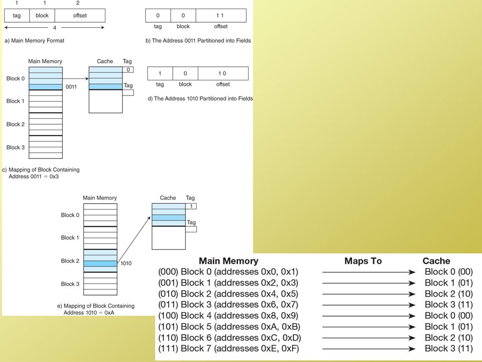
Direct Mapped Cache Tag s-r Line or Slot r Word w 8 14 2
Assume m refill lines A line j in memory will be found in cache at location j mod m Since each line has 1 and only 1 location in cache, there is no need for a replacement strategy This yields poor hit rate but fast performance (and cheap) All addresses are broken into 3 parts a line number (to determine the line in cache) a word number the rest is the tag – compare the tag to make sure you have the right line Here you can see the pattern of how memory blocks are placed into cache blocks. Consider for the 24 bit address shown in the slide that the CPU has generated the following memory address: This becomes tag: Line: (line #60) Word: 01 (word 3) So we go to line 60 and compare the tag to what is stored in the cache tag for that line (refer back 2 slides and you can see how the cache stores for each line the data plus a tag plus a valid bit). If the tags match, we have a hit. If they don’t, we have a miss. The DM cache is the simplest to implement, the cheapest and the fastest. Also, it uses the smallest space for tags. However, if we have a miss, we have to move the item from memory into line 60 (for this example) with no choice, so it is unable to utilize a replacement strategy and therefore will have the worst hit rate of the 3 types of caches. So we have a tradeoff, better hit time and cheaper for worse hit rate. We cover these issues in detail in CSC 562 where we study the tradeoff between hit time and hit rate. Assume 24 bit addresses, if the cache has lines, each storing 4 words, then we have the following: Tag s-r Line or Slot r Word w 8 14 2
 All addresses are broken into 3 parts. a line number (to determine the line in cache) a word number. the rest is the tag – compare the tag to make sure you have the right line. Here you can see the pattern of how memory blocks are placed into cache blocks. Consider for the 24 bit address shown in the slide that the CPU has generated the following memory address: This becomes tag: Line: (line #60) Word: 01 (word 3) So we go to line 60 and compare the tag to what is stored in the cache tag for that line (refer back 2 slides and you can see how the cache stores for each line the data plus a tag plus a valid bit). If the tags match, we have a hit. If they don’t, we have a miss. The DM cache is the simplest to implement, the cheapest and the fastest. Also, it uses the smallest space for tags. However, if we have a miss, we have to move the item from memory into line 60 (for this example) with no choice, so it is unable to utilize a replacement strategy and therefore will have the worst hit rate of the 3 types of caches. So we have a tradeoff, better hit time and cheaper for worse hit rate. We cover these issues in detail in CSC 562 where we study the tradeoff between hit time and hit rate. Assume 24 bit addresses, if the cache has lines, each storing 4 words, then. we have the following: Tag s-r. Line or Slot r. Word w")
11
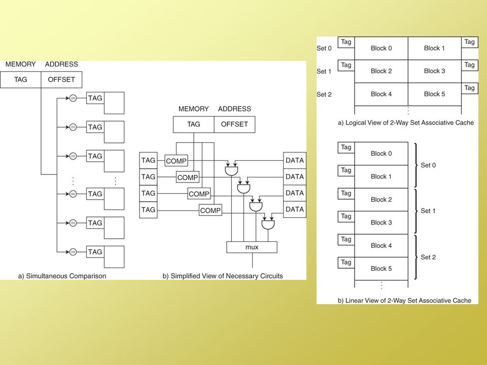
Associative Cache Any line in memory can be placed in any line in cache No line number portion of the address, just a tag and a word within the line Because the tag is longer, more tag storage space is needed in the cache, so these caches need more space and so are more costly All tags are searched simultaneously using “associative memory” to find the tag requested This is both more expensive and slower than direct-mapped caches but, because there are choices of where to place a new line, associative caches require a replacement strategy which might require additional hardware to implement A fully associative cache has no block numbers. Therefore, all bits for an address outside of the word # become the tag. The advantage is that any block from memory can be placed in any block in cache letting us use the replacement strategy to its fullest. The disadvantages are that the full associative cache: is the most expensive is the slowest requires the most amount of tag space So we have a tradeoff here of the best hit rate for the poorest hit time. Now notice that since we have no block numbers, most of the address is a tag. Consider two caches of 32K Words where the number of words per line is 2. This means 4 words per line giving us 16K blocks. 16K blocks requires 14 bits to denote a block number. Assume main memory addresses are 24 bits. The DM cache will use 24 – 14 – 2 = 8 bits for the tag, the Fully Associative cache will not have block numbers, so we have 24 – 2 = 22 bits for the tag. Since there are 16K blocks, the DM cache uses 8 * 16K = 128K bits = 16 Kbytes for tag storage while the Fully Associative cache uses 22 * 16K = 352Kbits = 44KBytes for tags. So the DM cache is made up of 32KWords + 16KBytes of total space and the Fully Associative cache is made up of 32KWords + 44KBytes of total space. If we have 32 bit words, then the DM cache is about 144KBytes and the Fully Associative cache is about 172KBytes! Notice how big the tag is, our cache now requires more space to store more tag space! From our previous example, our address now looks like this: Tag 22 bit Word 2 bit

12
Set Associative Cache In order to provide some degree of variability in placement, we need more than a direct-mapped cache A 2-way set associative cache provides 2 refill lines for each line number Instead of n refill lines, there are now n / 2 sets, each set storing 2 refill lines We can think of this as having 2 direct-mapped caches of half the size Because there are ½ as many refill lines, the line number has 1 fewer bits and the tag number has 1 more We can expand this to: 4-way set associative 8-way set associative 16-way set associative, etc As the number increases, the hit rate improves, but the expense also increases and the hit time gets worse Eventually we reach an n-way cache, which is a fully associative cache The set associative cache is the compromise between the two extremes. We can use a replacement strategy giving us a better hit rate than the DM cache, but we don’t have as much waste in tag space, nor is it as slow as the fully associative cache. A 2-way set of associative with k blocks is like a DM cache of 2*k blocks. That is, we take our DM cache and divide it into 2 sets of k blocks each. A 4-way set associative cache has 4 sets, etc. The bigger the “way” is, the more the replacement strategy can impact the hit rate (improving it) but the slower and more costly the cache will be. Notice that if a DM cache uses 14 bits for the refill line and 8 bits for the tag, the 2-way will use 13 bits for the refill line (half as many refill lines) so there is 1 extra bit for the tag. Tag s-r Line or Slot r Word w 9 13 2
 but the slower and more costly the cache will be. Notice that if a DM cache uses 14 bits for the refill line and 8 bits for the tag, the 2-way will use 13 bits for the refill line (half as many refill lines) so there is 1 extra bit for the tag. Tag s-r. Line or Slot r. Word w")
14
Replacement And Write Strategies
When we need to bring in a new line from memory, we will have to throw out a line Which one? No choice in a direct-mapped cache For associative and set-associative, we have choices We rely on a replacement strategy to make the best choice this should promote locality of reference 3 replacement strategies are Least recently used (hard to implement, how do we determine which line was least recently used?) First-in first out (easy to implement, but not very good results) Random If we are to write a datum to cache, what about writing it to memory? Write-through – write to both cache and memory at the same time if we write to several data in the same line though, this becomes inefficient Write-back – wait until the refill line is being discarded and write back any changed values to memory at that time This causes stale or dirty values in memory The Least Recently Used replacement strategy gives us the best prediction on what won’t be used again in the near future, so is the best one. The problem is its impossible to implement quickly. How do we detect which refill lines was least recently used? We can time stamp whenever each is accessed. But now to determine the least recently used block, we have to compare all time stamps. An approximately approach might be useful: add a LRU bit. Each time a block is referenced, set the bit to 1. Now find the first block with bit = 0 and replace it. Occasionally reset all bits. This is especially useful in a 2-way set associative cache, less so for a fully associative cache. Notice FIFO is straightforward, we only need to add a queue which stores refill line numbers. But its performance turns out to be no better, and sometimes worse, than random. So the most common implementation for a replacement strategy is actually random! We explore the performance of these approaches in 562. The other thing to consider is – what happens if we write a datum to a cache block? We will only write data and writes (stores) are far less frequent than reads (loads), but if it happens, we have to decide whether to immediately update memory, or let memory sit un-updated for awhile. The write through approach is less efficient because memory access is time consuming. Consider if we update 4 data all in the same block. Its better to replace the entire block at once rather than having 4 updates of memory. The only danger is if someone else can access memory before we update it. This is known as the cache coherence problem. Also note that we have to remember if we need to update memory or not, so we add a valid bit to our cache (see 5 slides back). If we have to discard a block and the block has been modified, we need to save it back to memory rather than just discarding it!
 First-in first out (easy to implement, but not very good results) Random. If we are to write a datum to cache, what about writing it to memory Write-through – write to both cache and memory at the same time. if we write to several data in the same line though, this becomes inefficient. Write-back – wait until the refill line is being discarded and write back any changed values to memory at that time. This causes stale or dirty values in memory. The Least Recently Used replacement strategy gives us the best prediction on what won’t be used again in the near future, so is the best one. The problem is its impossible to implement quickly. How do we detect which refill lines was least recently used We can time stamp whenever each is accessed. But now to determine the least recently used block, we have to compare all time stamps. An approximately approach might be useful: add a LRU bit. Each time a block is referenced, set the bit to 1. Now find the first block with bit = 0 and replace it. Occasionally reset all bits. This is especially useful in a 2-way set associative cache, less so for a fully associative cache. Notice FIFO is straightforward, we only need to add a queue which stores refill line numbers. But its performance turns out to be no better, and sometimes worse, than random. So the most common implementation for a replacement strategy is actually random! We explore the performance of these approaches in 562. The other thing to consider is – what happens if we write a datum to a cache block We will only write data and writes (stores) are far less frequent than reads (loads), but if it happens, we have to decide whether to immediately update memory, or let memory sit un-updated for awhile. The write through approach is less efficient because memory access is time consuming. Consider if we update 4 data all in the same block. Its better to replace the entire block at once rather than having 4 updates of memory. The only danger is if someone else can access memory before we update it. This is known as the cache coherence problem. Also note that we have to remember if we need to update memory or not, so we add a valid bit to our cache (see 5 slides back). If we have to discard a block and the block has been modified, we need to save it back to memory rather than just discarding it!")
15
Virtual Memory Just as DRAM acts as a backup for cache, hard disk (known as the swap space) acts as a backup for DRAM This is known as virtual memory Virtual memory is necessary because most programs are too large to store entirely in memory Also, there are parts of a program that are not used very often, so why waste the time loading those parts into memory if they won’t be used? Page – a fixed sized unit of memory – all programs and data are broken into pages Paging – the process of bringing in a page when it is needed (this might require throwing a page out of memory, moving it back to the swap disk) The operating system is in charge of Virtual Memory for us it moves needed pages into memory from disk and keeps track of where a specific page is placed By segmenting memory into fixed sized units, any program page can fit anywhere into memory as long as the memory “slot” is available. We will call these slots frames. So memory consists of M equal sized frames. A program consists of N pages each page is equal in size to one frame. The OS loads pages into available frames.
 The operating system is in charge of Virtual Memory for us. it moves needed pages into memory from disk and keeps track of where a specific page is placed. By segmenting memory into fixed sized units, any program page can fit anywhere into memory as long as the memory slot is available. We will call these slots frames. So memory consists of M equal sized frames. A program consists of N pages each page is equal in size to one frame. The OS loads pages into available frames.")
16
The Paging Process When the CPU generates a memory address, it is a logical (or virtual) address The first address of a program is 0, so the logical address is merely an offset into the program or into the data segment For instance, address 25 is located 25 from the beginning of the program But 25 is not the physical address in memory, so the logical address must be translated (or mapped) into a physical address Assume memory is broken into fixed size units known as frames (1 page fits into 1 frame) We know the logical address as its page # and the offset into the page We have to translate the page # into the frame # (that is, where is that particular page currently be stored in memory – or is it even in memory?) Thus, the mapping process for paging means finding the frame # and replacing the page # with it Since pages are loaded into available frames, pages are not necessarily in order any more and may be distributed quite randomly. We need to keep track of which page is in which frame so that we can map a page into a frame location.
 into a physical address. Assume memory is broken into fixed size units known as frames (1 page fits into 1 frame) We know the logical address as its page # and the offset into the page. We have to translate the page # into the frame # (that is, where is that particular page currently be stored in memory – or is it even in memory ) Thus, the mapping process for paging means finding the frame # and replacing the page # with it. Since pages are loaded into available frames, pages are not necessarily in order any more and may be distributed quite randomly. We need to keep track of which page is in which frame so that we can map a page into a frame location.")
17
Example of Paging Here, we have a process of 8 pages but only 4 physical frames in memory – therefore we must place a page into one of the available frames in memory whenever a page is needed At this point in time, pages 0, 3, 4 and 7 have been moved into memory at frames 2, 0, 1 and 3 respectively This information (of which page is stored in which frame) is stored in memory in a location known as the Page Table. The page table also stores whether the given page has been modified (the valid bit – much like our cache) This is a trivial example. A program might be more than 8 pages, and main memory will certainly be more than 4 frames. Notice that the program might be larger in size than memory as in this example, or smaller. But most likely the user is running multiple programs, so the sum of the program sizes is probably greater than the amount of memory available. The page table stores our mapping from page # to frame #.
 is stored in memory in a location known as the Page Table. The page table also stores whether the given page has been modified (the valid bit – much like our cache) This is a trivial example. A program might be more than 8 pages, and main memory will certainly be more than 4 frames. Notice that the program might be larger in size than memory as in this example, or smaller. But most likely the user is running multiple programs, so the sum of the program sizes is probably greater than the amount of memory available. The page table stores our mapping from page # to frame #.")
18
A More Complete Example
Virtual address mapped to physical address the page table Address 1010 is page 101, item 0 Page 101 (5) is located in frame 11 (3) so the item 1010 is found at 110 Notice how we simply swap out the page # and replace it with the frame #. The page offset remains the same (the page offset = the frame offset). Again in this example, the program is bigger than memory, which is only 8 bytes in this case! A page fault arises if the given page isn’t currently in memory. Logical and physical memory for our program
 is. located in frame 11. (3) so the item is found at 110. Notice how we simply swap out the page # and replace it with the frame #. The page offset remains the same (the page offset = the frame offset). Again in this example, the program is bigger than memory, which is only 8 bytes in this case! A page fault arises if the given page isn’t currently in memory. Logical and physical memory for our program.")
19
Page Faults Just as cache is limited in size, so is main memory – a process is usually given a limited number of frames What if a referenced page is not currently in memory? The memory reference causes a page fault The page fault requires that the OS handle the problem The process’ status is saved and the CPU switches to the OS The OS determines if there is an empty frame for the referenced page, if not, then the OS uses a replacement strategy to select a page to discard if that page is dirty, then the page must be written to disk instead of discarded The OS locates the requested page on disk and loads it into the appropriate frame in memory The page table is modified to reflect the change Page faults are time consuming because of the disk access – this causes our effective memory access time to deteriorate badly!

20
Another Paging Example
Notice how we determine the number of bits for a page number, a frame number and a page/frame offset: log 2 virtual address space (size of program) = number of bits for page # log 2 physical address space (size of memory) = number of bits for frame # log 2 page/frame size = number of bits for page/frame offset Now the page table will store 1 entry for every page in the program. Thus, a page table will have X entries where X = program size / page size In the above example, our program is 8K and our page size is 1K, so we have 8 pages We store the page table in main memory, and for a large program, this can take up a lot of space (consider a computer with 1G of memory and pages of 1K in size, running MS Windows, which might be 4G, this would require 4G/1K = 4M (4 million) entries!) Here, we have 13 bits for our addresses even though main memory is only 4K = 212
 = number of bits for page # log 2 physical address space (size of memory) = number of bits for frame # log 2 page/frame size = number of bits for page/frame offset. Now the page table will store 1 entry for every page in the program. Thus, a page table will have X entries where X = program size / page size. In the above example, our program is 8K and our page size is 1K, so we have 8 pages. We store the page table in main memory, and for a large program, this can take up a lot of space (consider a computer with 1G of memory and pages of 1K in size, running MS Windows, which might be 4G, this would require 4G/1K = 4M (4 million) entries!) Here, we have 13 bits for our addresses even though main memory is only 4K = 212.")
21
The Full Paging Process
We want to avoid memory accesses (we prefer cache accesses) – but if every memory access now requires first accessing the page table, which is in memory, it slows down our computer So we move the most used portion of the page table into a special cache known as the Table Lookaside Buffer or Translation Lookaside Buffer, abbrev. as the TLB The process is also shown in the next slide as a flowchart In order to allow our programs to run even if they can’t fit in memory, we need virtual memory. However, to do the mapping, we need to access the page table, in memory. Thus, every access needs at least 1 memory access, to the page table, even if the item (program instruction or datum) is in cache! To alleviate this problem, we take the most recently used portion of the page table and move it to a special cache, the TLB. So now the pattern of access is this: CPU generates address Go to TLB to get page # frame # mapping If not found in TLB, go to page table to do mapping If the page is not in memory, generate a page fault, else we have the physical address Go to L1 cache and if found, return to CPU (if load) If not found, go to L2 cache If not found, go to main memory On a page fault, we invoke the OS to deal with disk access, this is so time consuming that it ruins any efficiency gained from using the TLB and cache
 – but if. every memory access now requires. first accessing the page table, which. is in memory, it slows down our. computer. So we move the most used portion of. the page table into a special cache known. as the Table Lookaside Buffer or. Translation Lookaside Buffer, abbrev. as the TLB. The process is also shown in the next. slide as a flowchart. In order to allow our programs to run even if they can’t fit in memory, we need virtual memory. However, to do the mapping, we need to access the page table, in memory. Thus, every access needs at least 1 memory access, to the page table, even if the item (program instruction or datum) is in cache! To alleviate this problem, we take the most recently used portion of the page table and move it to a special cache, the TLB. So now the pattern of access is this: CPU generates address. Go to TLB to get page # frame # mapping. If not found in TLB, go to page table to do mapping. If the page is not in memory, generate a page fault, else we have the physical address. Go to L1 cache and if found, return to CPU (if load) If not found, go to L2 cache. If not found, go to main memory. On a page fault, we invoke the OS to deal with disk access, this is so time consuming that it ruins any efficiency gained from using the TLB and cache.")
22
Here is the process in a flowchart

23
A Variation: Segmentation
One flaw of paging is that, because a page is fixed in size, a chunk of code might be divided into two or more pages So page faults can occur any time Consider, as an example, a loop which crosses 2 pages If the OS must remove one of the two pages to load the other, then the OS generates 2 page faults for each loop iteration! A variation of paging is segmentation instead of fixed size blocks, programs are divided into procedural units equal to their size We subdivide programs into procedures We subdivide data into structures (e.g., arrays, structs) We still use the “on-demand” approach of virtual memory, but when a block of code is loaded into memory, the entire needed block is loaded in Segmentation uses a segment table instead of a page table and works similarly although addresses are put together differently But segmentation causes fragmentation – when a segment is discarded from memory for a new segment, there may be a chunk of memory that goes unused One solution to fragmentation is to use paging with segmentation Consider the following code: for(i=0;i<n;i++) a[i] = a[i] + 1; Assume that the first part of the for-loop is stored in page 0 and the latter half with the assignment statement is stored in page 1. Also assume i and n are stored in page 2 but the array a is stored in page 3. Further, assume that this program is only given 2 frames by the OS. We have the following situation: Start the for loop, page fault (page 0 is loaded one of the available frames) Access i and n, page fault (page 2 is loaded into the other frame) Read the assignment statement, page fault, load page 1 in place of page 0 Access array a, page fault, load page 3 in place of page 2 Repeat We have 4 page faults for each loop iteration! To resolve this problem, we might divide our program and code into logical units (functions, data structures) rather than arbitrary sized units dictated by an architect who designed the memory layout. These units are called segments.
 We still use the on-demand approach of virtual memory, but when a block of code is loaded into memory, the entire needed block is loaded in. Segmentation uses a segment table instead of a page table and works similarly although addresses are put together differently. But segmentation causes fragmentation – when a segment is discarded from memory for a new segment, there may be a chunk of memory that goes unused. One solution to fragmentation is to use paging with segmentation. Consider the following code: for(i=0;i<n;i++) a[i] = a[i] + 1; Assume that the first part of the for-loop is stored in page 0 and the latter half with the assignment statement is stored in page 1. Also assume i and n are stored in page 2 but the array a is stored in page 3. Further, assume that this program is only given 2 frames by the OS. We have the following situation: Start the for loop, page fault (page 0 is loaded one of the available frames) Access i and n, page fault (page 2 is loaded into the other frame) Read the assignment statement, page fault, load page 1 in place of page 0. Access array a, page fault, load page 3 in place of page 2. Repeat. We have 4 page faults for each loop iteration! To resolve this problem, we might divide our program and code into logical units (functions, data structures) rather than arbitrary sized units dictated by an architect who designed the memory layout. These units are called segments.")
24
Effective Access With Paging
We modify our previous formula to include the impact of paging: effective access time = hit time0 + miss rate0 * (hit time1 + miss rate1 * (hit time2 + miss rate2 * miss penalty2)) Level 0 is on-chip cache Level 1 is off-chip cache Level 2 is main memory Level 3 is disk (miss penalty2 is disk access time, which is lengthy) Example: On chip cache hit rate is 90%, hit time is 5 ns, off chip cache hit rate is 96%, hit time is 10 ns, main memory hit rate is 99.8%, hit time is 60 ns, memory miss penalty is 10 ms = 10,000 ns memory miss penalty is the same as the disk hit time, or disk access time Access time = 5 ns * (10 ns * (60 ns * 10,000 ns)) = 6.32 ns So our memory hierarchy adds over 20% to our memory access The above formula is inaccurate because we have to add into this the time it takes to access the TLB. Our formula should be: EAT = paging info access + data/instruction access Paging info access = TLB access time + TLB miss rate * main memory access time Also note that if we have a page fault, we don’t do the data/instruction access as implied in the formula in the slide.
) Level 0 is on-chip cache. Level 1 is off-chip cache. Level 2 is main memory. Level 3 is disk (miss penalty2 is disk access time, which is lengthy) Example: On chip cache hit rate is 90%, hit time is 5 ns, off chip cache hit rate is 96%, hit time is 10 ns, main memory hit rate is 99.8%, hit time is 60 ns, memory miss penalty is 10 ms = 10,000 ns. memory miss penalty is the same as the disk hit time, or disk access time. Access time = 5 ns * (10 ns * (60 ns * 10,000 ns)) = 6.32 ns. So our memory hierarchy adds over 20% to our memory access. The above formula is inaccurate because we have to add into this the time it takes to access the TLB. Our formula should be: EAT = paging info access + data/instruction access. Paging info access = TLB access time + TLB miss rate * main memory access time. Also note that if we have a page fault, we don’t do the data/instruction access as implied in the formula in the slide.")
25
Memory Organization Here we see a typical memory layout:
This is just an example of a memory layout. Notice that this machine has 5 caches, 2 TLBs, 2 on-chip caches (one each for data and instruction) and an off-chip cache. The off-chip cache will store both instructions and data, but on the chip, we will most likely have separate data and instruction caches. Probably though the on-chip caches will be direct-mapped or 2-way set associative, and the TLB will be the same. The off-chip cache may be 2-way, 4-way, 8-way or fully associative (although fully associative caches are pretty rare). Here we see a typical memory layout: Two on-chip caches: one for data, one for instructions with part of each cache Reserved for a TLB One off-chip cache to back-up both on-chip caches Main memory, backed up by virtual memory
 and an off-chip cache. The off-chip cache will store both instructions and data, but on the chip, we will most likely have separate data and instruction caches. Probably though the on-chip caches will be direct-mapped or 2-way set associative, and the TLB will be the same. The off-chip cache may be 2-way, 4-way, 8-way or fully associative (although fully associative caches are pretty rare). Here we see a typical memory layout: Two on-chip caches: one for data, one for instructions with part of each cache. Reserved for a TLB. One off-chip cache to back-up both on-chip caches. Main memory, backed up by virtual memory.")
Similar presentations


 ECE 445 – Computer Organization The slides included herein were taken from the materials accompanying Computer Organization.>")
>")

 size of.>")


 –Objectives in Memory Design –Memory Types –Memory Hierarchies Memory Management (Software.>")

 DRAM: –value is stored as a charge.>")


