Download presentation
Presentation is loading. Please wait.

2
Part One: Material Properties Part Two: Forces and Torque Assessment

3
1) A Structural Engineering Achievement, eg Sydney Harbour Bridge Eiffel Tower Burj Khalifa Three Gorges Dam 2) A Structural Engineering Failure, eg Tacoma Narrows Bridge I-35W Mississippi River bridge St. Francis Dam Hyatt Regency Walkway

4
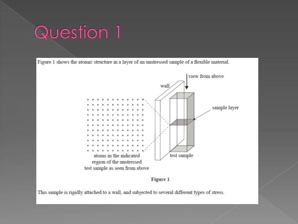
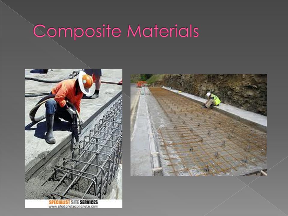
This topic is all about learning what happens to different materials when we apply forces to them.

5
Once we know this, we start to have enough information to plan how to build bridges, buildings, roads, and a multitude of different structures

7
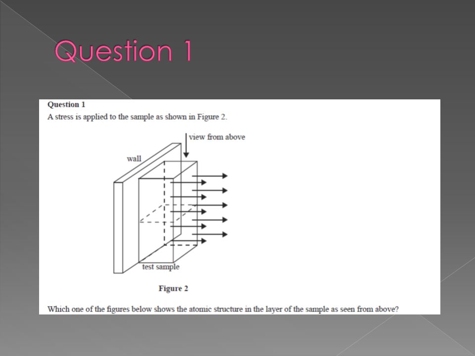
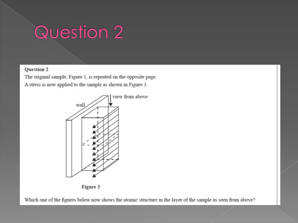
Consider a cube of plasticine. What forces could you apply to it to attempt to change its shape? Tension (Pull) Compression (Push) Shear Torsion Bend
 Compression (Push) Shear Torsion Bend.")
13
If you are having trouble figuring out what is in compression, and what is in tension, do the following thought experiment: Replace one of the materials with a piece of string. Will the structure still hold up? If so, then that material was in tension

14
2012. Q 11 Pg 32 2011. Q 7 pg 37, and Q 11 pg 39

15
A girl stands on a wooden bridge, and it bends downwards. Which part of the bridge is in compression, and which part is in tension?

16
Some materials are strong in compression, and weak in tension, and vice versa. Concrete is strong in compression, but weak in tension. We can add steel reinforcing rods, because steel rods are strong in tension.

18
Sample Q 10 Pg 26 2012. Q 12 Pg 33 2011. Q 10 Pg 38

19
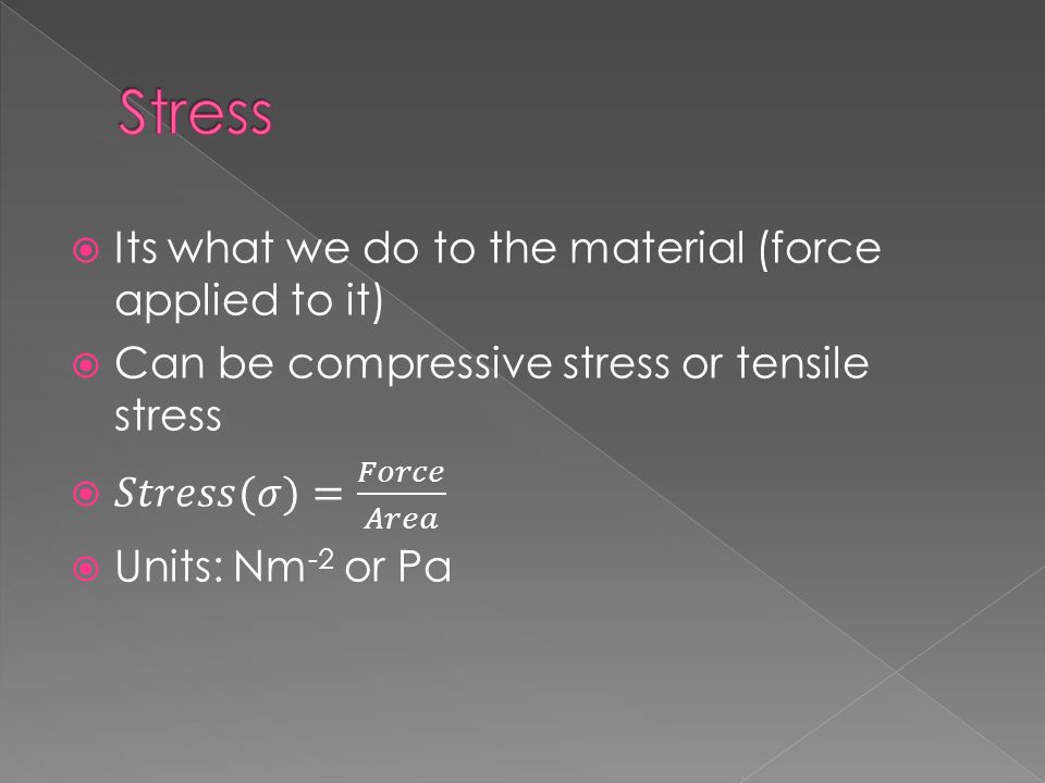
When we test materials, we have two main concepts we need to measure: Stress and Strain To do this we get the material (eg a steel girder), clamp it into a machine that can either apply a compression or tensile force and measure the how much it compresses/extends with each force.
, clamp it into a machine that can either apply a compression or tensile force and measure the how much it compresses/extends with each force.")
21
Question 4. Calculate the stress being applied to a steel girder if it has a cross sectional area of 0.02m 2, and a force applied of 5000N Question 5. Calculate the stress being applied to a steel girder if it has a cross sectional area of 0.05m 2, and a force applied of 40kN Question 6. Calculate the cross sectional area of an aluminium bar than has a 20kN force applied, and is subjected to a stress of 2M Nm -2

23
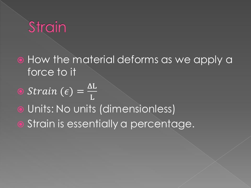
Question 7. Calculate the strain if a steel girder, originally 10m long, is compressed by 2cm Question 8. Calculate the strain if a carbon fibre material, originally 10cm is stretched to a new length of 10.005cm Question 9. A steel girder is found to have a tensile strain of ε = 0.04. If its original length was 1m, what is its new length?

24
The results of our testing of the material Draw on board

25
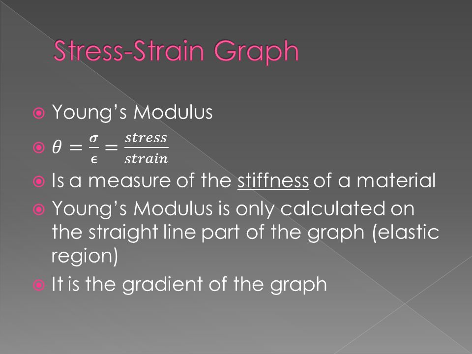
Usually two distinct regions: Elastic Region (straight line) Plastic Region (not straight) Any material compressed or stretched less than the elastic limit, will go back to its original shape after the force is removed. Any material that enters the plastic zone will have permanent deformations.

26
The strength of a material is the stress that will cause it to break or fail completely.

27
Brittle materials have a very small plastic region (suddenly they just break!) Ductile materials have a large plastic region (can stretch and stretch, and stay stretched out)
 Ductile materials have a large plastic region (can stretch and stretch, and stay stretched out)")
29
Question 10 Calculate Young’s Modulus for a human bone that shows a strain of 0.0005 when placed under a stress of 7M Pa Question 11 Calculate Young’s Modulus for a marble column, that is 2m long, cross sectional area of 0.5m 2, and under a force of 5x10 7 N undergoes a compression of 4mm

30
Young’s Modulus of Snakes

31
Sample. Q 1, 2, 4, 5, 6. 2012. Q 2, 3, 4, 5.

32
Extension ( Δx) [m] Force ( F) [N]
![Extension ( Δx) [m] Force ( F) [N]](http://images.slideplayer.com/24/7084225/slides/slide_32.jpg "Extension ( Δx) [m] Force ( F) [N]")
33
Similarly the area under a stress-strain graph is called the strain energy What is the area under this graph? 100 Strain Stress [MPa] 0 200 0 0.010.02

34
100 Stress [MPa] 0 200 0 0.010.02 Strain A B
![100 Stress [MPa] Strain A B](http://images.slideplayer.com/24/7084225/slides/slide_34.jpg "100 Stress [MPa] Strain A B")
35
Basically F x d = Work Unit: J Area x length = Volume Unit: m 3 Strain Energy Units: Jm -3

36
The strain energy needed to break a material gives us a measure of its toughness.

37
Sample. Q 3, 7 2012. Q 6, 7 2011. Q 1, 2, 3, 4, 5, 6.

39
For each question 1. Draw the situation 2. Answer the question 3. Build the contraption to test your answer.

40
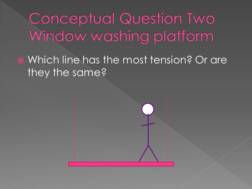
Which line has the most tension? Or are they the same?

42
Which rope has the most tension? Or are they the same?

43
The ropes holding the monkey have the same force. Are they bigger, smaller, or same than in the last question?

44
Train in middle, but pillars not centred. Is the normal force provided by both pillars the same? If not, which is bigger?

45
Try undoing a nut and bolt with your bare hands Why is it easier to use a spanner? Try hold the spanner close to the nut, is it easier or harder to undo? What if you were to apply a force outwards (pull on the spanner)
.")
46
Force r Axis of rotation

47
Force r Axis of rotation θ

48
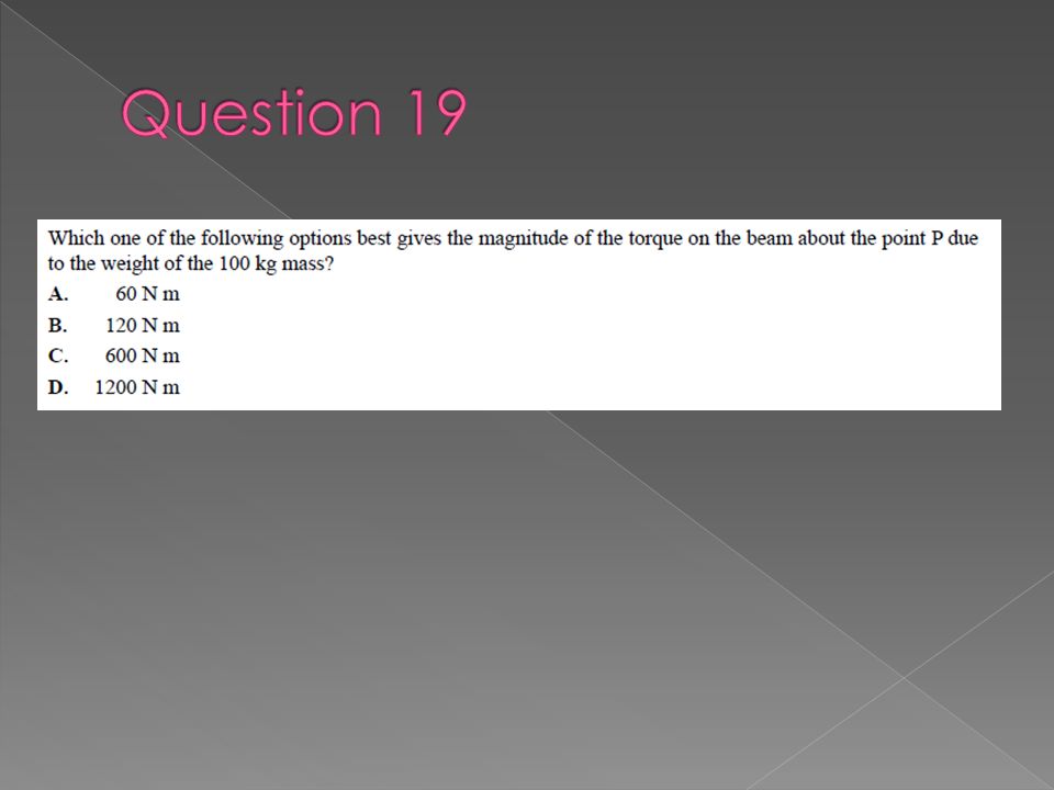
Question 12 Calculate the torque when a 10N force is applied at the end of a 10cm spanner 10N 10cm

49
Question 13 Calculate the torque applied to a 10cm spanner, when the force is 10N, but is applied halfway along, and at a 30 o angle 10N 5cm 30 o

50
Question 14 If an 8N force applied to a wrench produces a 1.6Nm torque, what distance is the force applied from the axis of rotation?

51
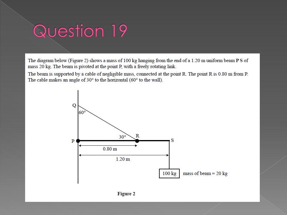
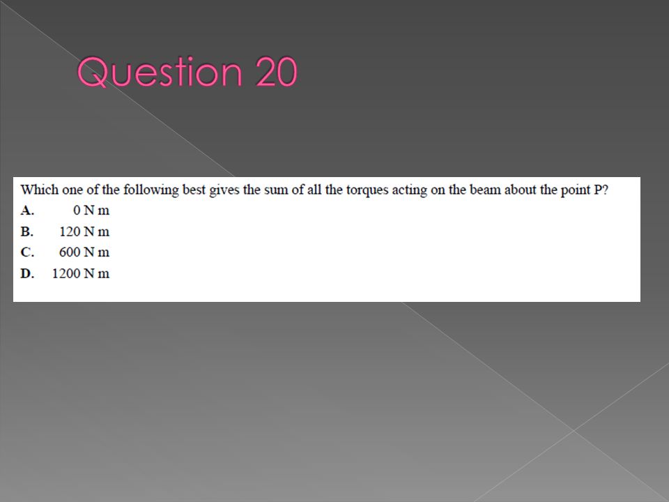
A structure is in static equilibrium (not moving) if TWO conditions are met: 1. Sum of all forces acting on it are zero (Newton’s First Law) 2. Sum of clockwise torques (moments) equals some of anticlockwise torques (moments)
 2. Sum of clockwise torques (moments) equals some of anticlockwise torques (moments).")
52
A bridge is being build out of a 10m, 1000kg slab of concrete, resting on two pillars. If the left pillar provides a normal force of 5000N, how much does the other provide? 2m 10m

53
Same 1000kg bridge, but it is to be built so that one pillar is at the end What is the normal force provided by EACH pillar now? 10m 2m

54
Two hints: 1) The weight force of the bridge can be considered as acting from a single point. 2) Is the bridge rotating? No! So the axis of rotation can be chosen to be anywhere! 10m 2m
 Is the bridge rotating. No. So the axis of rotation can be chosen to be anywhere. 10m 2m.")
57
A cantilever is essentially a diving board. It is a structure where it needs an upwards and downwards normal force How could we make the following structure steady? Water

58
2012. Q 8, 9 2011. Q 9

59
Struts and ties can help distribute a load or reduce the load in a beam or a column.

64
Sample. Q 8, 9 2011. Q 7, 8

65
An arch is a useful building structure as it supports the weight above it using only compression forces.

Similar presentations


>")


