Download presentation
Presentation is loading. Please wait.

1
Behavior, Modeling and Design of Shear Wall-Frame Systems
Naveed Anwar Asian Center for Engineering Computations and Software, ACECOMS, AIT

2
The Basic Issues Modeling and analysis issues
Transfer of loads to shear walls Modeling of shear walls in 2D Modeling of shear Walls in 3D Interaction of shear-walls with frames Design and detaining issues Determination of rebars for flexure Determination of rebars for shear Detailing of rebars near openings and corners Design and detailing of connection between various commonest of cellular shear walls

3
Shear Wall – Common Misconceptions
Due to misleading name “Shear Wall” The dominant mode of failure is shear Strength is controlled by shear Designed is governed primarily by shear Force distribution can be based on relative stiffness

4
Shear Wall or Column

5
Shear Wall or Frame Shear Wall or Frame ? Shear Wall Frame

6
Shear Wall and Frame Behavior

7
Shear Wall and Truss Behavior

8
Shear Wall and Frame Frame Behavior Shear Wall Behavior

9
Shear Wall and Frame Interaction

10
Frame and Frame-Shear Wall
B-4 B-1 B-2 B-3 B-4

11
Shear Wall and Frame Interaction
Frames Deform Predominantly in a shear mode Source of lateral resistance is the rigidity of beam-column/slab joints Shear Wall Deform Essentially in bending mode Shear deformations are rarely significant Only very low shear walls with H/W ratio <1 fail in shear Behave mostly like a slender cantilever Designed to resist the combined effect of axial, bending and shear

12
Shear Walls, Frames and Shear Wall-Frames
The Basic Behavior of Shear Walls, Frames and Shear Wall-Frames

13
For each 10, 20 and 30 story buildings
Case Studies: Shear Wall–Frame Interaction For each 10, 20 and 30 story buildings Only Shear Wall ( Total 3 Cases ) Only Frame ( Total 3 Cases ) Only Shear + Frame ( Total 3 Cases ) Total 3x3 = 9 Cases
 Only Frame ( Total 3 Cases ) Only Shear + Frame ( Total 3 Cases ) Total 3x3 = 9 Cases.")
14
Case 1: Shear Wall–Frame Interaction
10 Story Wall D = cm Wall Thickness = 15 cm

15
Case 2: Shear Wall–Frame Interaction
10 Story Frame D = cm Beam Section = 60 cm x 30 cm Column Section = 50 cm x 50 cm

16
Case 3: Shear Wall–Frame Interaction
10 Story Wall and Frame D = 5.14 cm Wall Thickness = 15 cm Beam Section = 60 cm x 30 cm Column Section = 50 cm x 50 cm

17
Case 4: Shear Wall–Frame Interaction
20 Story Wall D = cm Wall Thickness = 20 cm

18
Case 5: Shear Wall–Frame Interaction
20 Story Frame D = cm Beam Section = 60 cm x 30 cm Column Section = 75 cm x 75 cm

19
Case 6: Shear Wall–Frame Interaction
20 Story Wall and Frame D = cm Wall Thickness = 20 cm Beam Section = 60 cm x 30 cm Column Section = 75 cm x 75 cm

20
Case 7: Shear Wall–Frame Interaction
30 Story Wall D = cm Wall Thickness = 30 cm

21
Case 8: Shear Wall–Frame Interaction
30 Story Frame D = cm Beam Section = 60 cm x 30 cm Column Section = 100 cm x 100 cm

22
Case 9: Shear Wall–Frame Interaction
30 Story Wall and Frame D = cm Wall Thickness = 30 cm Beam Section = 60 cm x 30 cm Column Section = 100 cm x 100 cm

23
Shear Wall–Frame Interaction

24
Shear Wall–Frame Interaction

25
Shear Wall–Frame Interaction

26
Shear Wall–Frame Interaction

27
Shear Wall–Frame Interaction
= Force / Stiffness Stiffness = Force / D For the cases considered here (30 story example): Stiffness Frame = 200 / = 04.90 Force=200 Deflection = 40.79 Stiffness Wall = 200 / = 00.56 Stiffness Frame + Wall = 200 / = 15.79 Stiffness Frame +Stiffness Wall = = 5.46 Stiffness Frame +Stiffness Wall Stiffness Frame + Wall
: Stiffness Frame = 200 / = Force=200 Deflection = Stiffness Wall = 200 / = Stiffness Frame + Wall = 200 / = Stiffness Frame +Stiffness Wall = = Stiffness Frame +Stiffness Wall Stiffness Frame + Wall.")
28
Shear Wall Moments for the Coupled System
Change in Shear Wall Moments Shear Wall Moments for the Coupled System

29
Coupling Element Moments

30
Shear Wall-Frame Load Distribution Curves

31
Khan-Sbarounis Curves
Deflected Shape of Shear Wall-Frame Interactive System Khan-Sbarounis Curves

32
Comparison of Shears and Moments in the Core wall
4 Different Layouts for Same Function Requirements Type A Type B Type C Type D

33
Typical Floor Plan- Structure Type A
Comparison of… : Type A Typical Floor Plan- Structure Type A

34
Typical Floor Plan- Structure Type B
Comparison of… : Type B Typical Floor Plan- Structure Type B

35
Typical Floor Plan- Structure Type C
Comparison of… : Type C Typical Floor Plan- Structure Type C

36
Typical Floor Plan- Structure Type D
Comparison of… : Type D Typical Floor Plan- Structure Type D

37
Comparison of Shears and Moments in the Core wall

38
Wall-Frame Interaction: Key Conclusions
The shear wall deform predominantly in bending mode The common assumptions to neglect the frames in lateral load resistance can lead to grossly erroneous results Consideration of shear wall-frame interaction leads to a more economic design The shear walls should be designed to resist the combined effect of axial, bending and shear Layout of the shear walls in plan in very important, both for vertical as well as gravity load

39
Basic Types of Shear Walls

40
Basic Types of Shear Walls

41
Basic Modeling Options for Shear Walls

42
Modeling of Walls using 1D Elements
Beam elements with rigid ends Beam elements in “Truss Model” L t H2 H1 Simple beam elements t x h L

43
Frame Model for Planer Walls
Specially Suitable when H/B is more than 5 The shear wall is represented by a column of section “B x t” The beam up to the edge of the wall is modeled as normal beam The “column” is connected to beam by rigid zones or very large cross-section H t B Rigid Zones

44
Frame Models for Cellular Walls
t Difficult to extend the concept to Non-planer walls Core Wall must be converted to “equivalent” column and appropriate “rigid” elements Can be used in 2D analysis but more complicated for 3D analysis After the core wall is converted to planer wall, the simplified procedure cab used for modeling H B 2t H t B

45
Modeling Walls using 2D Elements
Walls are subjected to in-plane deformations so 2D elements that have transnational DOF need to be used A coarse mesh can be used to capture the overall stiffness and deformation of the wall A fine mesh should be used to capture in-plane bending or curvature General Shell Element or Membrane Elements can be used to model Shear Walls

46
Modeling Walls Using Membrane
The Incomplete Membrane Element Nodes: 4 DOFs: 2 DOFs /Node Ux and Uy 2-Translation Dimension: 2 dimension element Shape: Regular / Irregular Properties: Modulus of Elasticity(E), Poisson ratio(v), Thickness( t ) This “Incomplete” Panel or Membrane Element does not connect with Beams completely and rotation DOF of beams and the ends are “Orphaned”
, Poisson ratio(v), Thickness( t ) This Incomplete Panel or Membrane Element does not connect with Beams completely and rotation DOF of beams and the ends are Orphaned")
47
Modeling Walls using Shell Elements
The Complete Membrane Element Nodes: 4 DOFs: 3 DOFs /Node Ux and Uy and Rz 2 Translation, 1 rotation Dimension: 2 dimension element Shape: Regular / Irregular Properties: Modulus of Elasticity(E), Poisson ratio(v), Thickness( t )
, Poisson ratio(v), Thickness( t )")
48
Using Incomplete Membrane Elements
Multiple elements greater accuracy in determination of stress distribution and allow easy modeling of openings Using Incomplete Membrane only (No Moment continuity with Beams) Using with Beams and or Columns are Required (Full Moment continuity with Beams and Columns)
 Using with Beams and or Columns are Required. (Full Moment continuity. with Beams and Columns)")
49
Using Complete Membrane Elements
Multiple elements greater accuracy in determination of stress distribution and allow easy modeling of openings Using Complete Membrane only (Moment continuity with Beams automatically provided) Using with Beams, Columns is NOT Required (Full Moment continuity with Beams and Columns)
 Using with Beams, Columns is NOT Required. (Full Moment continuity. with Beams and Columns)")
50
Connecting Walls to Slab
“Zipper” In general the mesh in the slab should match with mesh in the wall to establish connection Some software automatically establishes connectivity by using constraints or “Zipper” elements

51
Using Trusses to Model Shear Walls
The behavior of shear walls can be closely approximated by truss models: The vertical elements provide the axial-flexural resistance The diagonal elements provide the shear resistance Truss models are derived from the “strut-tie” concepts This model represents the “cracked” state of the wall where all tension is taken by ties and compression by concrete

52
Truss Model for Shear Walls
2 5 10 Comparing Deformation and Deflections of Shell Model with Truss Model

53
Truss Model for Shear Walls
2 5 10 Comparing Deformation and Deflections of Shell Model with Truss Model

54
Truss Models for Shear Walls
2 5 10 Comparing Axial Stress and Axial Force Patterns

55
Truss Models for Shear Walls
2 5 10 Uniaxial Biaxial

56
How to Construct Truss Models
For the purpose of analysis, assume the main truss layout based on wall width and floor levels Initial member sizes can be estimated as t x 2t for main axial members and t x t for diagonal members Use frame elements to model the truss. It is not necessary to use truss elements Generally single diagonal is sufficient for modeling but double diagonal may be used for easier interpretation of results The floor beams and slabs can be connected directly to truss elements t x t C t x 2t t B

57
Openings in Shear Walls
Very Small Openings may not alter wall behavior Medium Openings may convert shear wall to Pier and Spandrel System Very Large Openings may convert the Wall to Frame Beam Spandrel Column Wall Pier Pier

58
Openings in Shear Walls - Cellular
2 5

59
Openings in Shear Walls - Planer

60
Modeling Walls with Opening
Plate-Shell Model Truss Model Rigid Frame Model

61
Frame Model of Shear Walls
Based on Concept proposed by E.L. Wilson

62
Using Beam-Column to Model Shear Walls
4-Node plane element may not accurately capture the linear bending, because constant shear distribution is assumed in formulation but actually shear stress distribution is parabolic Since the basic philosophy of RC design is based on cracked sections, it is not possible to use the finite elements results directly for design Very simple model (beam-column) which can also captures the behavior of the structure, The results can be used directly to design the concrete elements.
 which can also captures the behavior of the structure, The results can be used directly to design the concrete elements.")
63
Shear Wall Design –Meshing
Shell Deformations: Three types of deformation that a single shell element could experience A single shell element in the program captures shear and axial deformations well. But a single shell element is unable to capture bending deformation.

64
Modeling Shear Walls Using Shell Elements
Plates with Columns and Beams A-2 Plates with Beams A-3 Plates with Columns A-4 Plates Only

65
Modeling Shear Walls Using Beam Elements
Single Bracing B-2 Double Bracing B-3 Column with Rigid Zones B-4 Columns with Flexible Zones

66
Comparison of Behavior

67
Comparison of Behavior (5 Floors)
")
68
Comparison of Behavior (15 Floors)
")
69
Comparison of Behavior (25 Floors)
")
70
Effect of Shear Wall Location

71
Modeling of Shear Walls
In ETABS

72
Shear Wall Design – Using ETABS
Special Considerations/Concepts: Zoning Pier Spandrel and Boundary Zone Labeling Spandrel Section Types Simplified Section (C, T or Linear) Uniform reinforcing section General Sections
 Uniform reinforcing section. General Sections.")
73
Shear Wall Design –Meshing
Wall Meshing and Load Transfer: Appropriate Meshing and labeling of Shear Walls is the key to proper modeling and design of walls No automatic meshing is available for walls (only manual) Loads are only transferred to walls at the corner points of the area objects that make up the wall Generally the Membrane or Shell type Elements should be used to model walls
 Loads are only transferred to walls at the corner points of the area objects that make up the wall. Generally the Membrane or Shell type Elements should be used to model walls.")
74
Shear Wall Design –Meshing
Wall Meshing: Piers and spandrels where bending deformations are significant (slender piers and spandrels), need to mesh the pier or spandrel into several elements If the aspect ratio of a pier or spandrel one shell element is worse than 3 to 1, consider additional meshing of the element to adequately capture the bending deformation
, need to mesh the pier or spandrel into several elements. If the aspect ratio of a pier or spandrel one shell element is worse than 3 to 1, consider additional meshing of the element to adequately capture the bending deformation.")
75
Shear Wall Design – Pier Zones
Pier Zone Labeling (Naming/Grouping) Pier labels are assigned to vertical area objects (walls) and to vertical line objects (columns) Objects that are associated with the same story level and have the same pier label are considered to be part of the same pier. Must assign a pier element a label before you can get output forces for the element or before you can design the element.
 Pier labels are assigned to vertical area objects (walls) and to vertical line objects (columns) Objects that are associated with the same story level and have the same pier label are considered to be part of the same pier. Must assign a pier element a label before you can get output forces for the element or before you can design the element.")
76
Shear Wall Design – Pier Zones
A single wall pier cannot extend over multiple stories Wall pier forces are output at the top and bottom of wall pier elements Wall pier design is only performed at stations located at the top and bottom of wall pier elements.

77
Shear Wall Design – Pier Zones
Piers Labeling Examples

78
Section for Design at II Floor Top
Shear Wall Design – Pier Zones General Comments on Case d: All of the area objects given the same label P1 Design is performed across the entire wall at each story level Wall forces would be provided for the entire wall at each story level Combined reinforcement is reported at the top and bottom of each floor (3-5 area objects) Section for Design at II Floor Top
 Section for Design at II Floor Top.")
79
Shear Wall Design – Pier Zones
General Comments on Case a: Common way to label piers At the upper level, Pier P1 is defined to extend all the way across the wall above the openings. Pier P2 makes up the wall pier to the left of the door opening. Pier P3 occurs between the door and window openings. Pier P4 occurs between the window opening and the edge of the wall. Pier P5 occurs below the window opening between the door and the edge of the wall. A similar labeling of piers occurs at the lower level.

80
Shear Wall Design – Pier Zones
General Comments on Case a (Common Way): At the upper level, Pier P1 is defined to extend all the way across the wall above the openings. Pier P2 makes up the wall pier to the left of the door opening. Pier P3 occurs between the door and window openings. Pier P4 occurs between the window opening and the edge of the wall. Pier P5 occurs below the window opening between the door and the edge of the wall. A similar labeling of piers occurs at the lower level.
: At the upper level, Pier P1 is defined to extend all the way across the wall above the openings. Pier P2 makes up the wall pier to the left of the door opening. Pier P3 occurs between the door and window openings. Pier P4 occurs between the window opening and the edge of the wall. Pier P5 occurs below the window opening between the door and the edge of the wall. A similar labeling of piers occurs at the lower level.")
81
Shear Wall Design – Pier Zones
General Comments on Case a (Common Way): Design pier –1 Design pier –2 Sections Design pier –3 Design pier –4 Output for Each Pier
: Design pier –1. Design pier –2. Sections. Design pier –3. Design pier –4. Output for Each Pier.")
82
Shear Wall Design – Spandrel Zones
Spandrel Zone Labeling (Naming/Grouping) Spandrel labels are assigned to vertical area objects (walls) and to horizontal line objects (beams) Unlike pier elements, a single wall spandrel element can be made up of objects from two (or more) adjacent story levels Must assign a spandrel element a label before you can get output forces for the element or before you can design the element
 Spandrel labels are assigned to vertical area objects (walls) and to horizontal line objects (beams) Unlike pier elements, a single wall spandrel element can be made up of objects from two (or more) adjacent story levels. Must assign a spandrel element a label before you can get output forces for the element or before you can design the element.")
83
Shear Wall Design – Pier Zones

84
Shear Wall Design – Spandrel Zones
Spandrels or Headers Wall spandrel forces are output at the left and right ends of wall spandrel Elements Wall spandrel design is only performed at stations located at the left and right ends of wall spandrel elements Multiple wall spandrel labels cannot be assigned to a single area object.

85
Shear Wall Design – Spandrel Zones
Examples: Spandrel Labeling

86
Concrete Shear Wall Design
Fully integrated wall pier and spandrel design ACI, UBC and Canadian Codes Design for static and dynamic loads Automatic integration of forces for piers and spandrel

87
Shear Wall Design Design based on : Equilibrium Conditions
Strain Compatibility Principle Linear Strain Variation

88
Interaction Surface for Shear Walls
P My Mx

89
Concrete Shear Wall Design
2D wall pier design and boundary-member checks 2D wall spandrel design 3D wall pier check for provided reinforcement Graphical Section Designer for concrete rebar location Graphical display of reinforcement and stress ratios Interactive design and review Summary and detailed reports including database formats

90
Shear Wall - Typical Design Process
While modeling define Shear Wall elements Choose the Shear Wall design code and review other related preferences and revise them if necessary Assign pier and spandrel labels Run the building analysis Assign overwrites Select Design Combos Start Designing Walls

91
Shear Wall - Typical Design Process
View Design Input and Output Information Design the Member Interactively Print Design Report Change Design Section if Required Re-run Design and Re-analyze if needed Repeat the Above Cycle

92
Shear Wall Design – Output

93
Shear Wall Design – Output

94
Shear Wall Design – Output

95
Shear Wall Design – Output

96
The Basic Issues Transfer of loads to shear walls
What is a Shear Wall? Modeling and analysis issues Transfer of loads to shear walls Modeling of shear walls in 2D Modeling of shear Walls in 3D Interaction of shear-walls with frames Design and detaining issues Determination of rebars for flexure Determination of rebars for shear Detailing of rebars near openings and corners Design and detailing of connection between various components of cellular shear walls

97
Avoid Eccentricity in Plan
Or

98
Reduce In-plane Bending in Floor

99
Vertical Irregularity
Expansion Joint No Shear Walls Balanced Shear Walls at All Levels Using Expansion Joints to eliminate some walls

100
Using Efficient Building Plan Shape

101
Design of Shear Walls

102
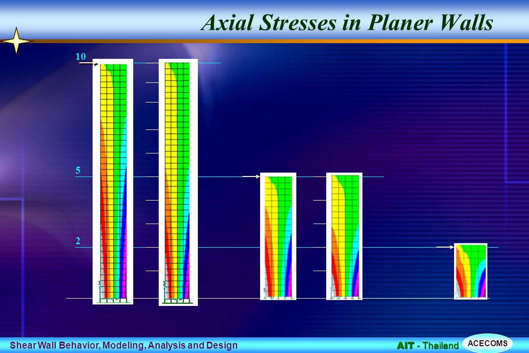
Axial Stresses in Planer Walls
2 5 10
103
Axial Stresses in Cellular Walls
2 5 10 Uniaxial Bending

104
Axial Stresses in Cellular Walls
2 5 10 Biaxial Bending

105
Getting Result from Frame Model
Design actions (P, Mx, My and V) are obtained directly Vx Vy P Mx My P V M
 are obtained directly. Vx. Vy. P. Mx. My. P. V. M.")
106
Getting Results from Truss Model
V P M C T xd xt xc Tension Member Compression Member

107
Getting Results From Shell Model
CL of wall V P M A A t f5 f4 f3 f2 T f1 f1, f2, …..fn are the nodal stresses at section A-A , obtained from analysis C x1

108
Interaction Curves - Uniaxial
The curve is generated by varying the neutral axis depth Safe Un-safe

109
Interaction Surface - Biaxial
Safe Un-safe The surface is generated by changing Angle and Depth of Neutral Axis

110
Interaction Surface and Curves

111
Narrow Planner Walls The capacity is almost completely un-axial
Moment capacity can be increased by providing Rebars at the corners

112
Cellular Wall – No Opening
The capacity is almost completely biaxial

113
Single Cell Walls

114
Double Cell Walls

115
Designing as Axial Zones

116
Axial Zone Model – Planer Wall

117
Axial Zones for Box Wall

118
Shear Design Spandrel Pier

119
Shear Design of Pier Determine Concrete shear capacity, Vc
Check if Vc exceeds the limit, if it does, section needs to be revised Determine steel Rebars for Vs=V-Vc Check additional steel for seismic requirements

120
ACI Equations for Pier Design
Basic Concrete Shear Capacity Concrete not to Exceed the limit Area of Steel Computed as

121
Shear Design for Spandrel
Determine Concrete shear capacity, Vc Check if Vc exceeds the limit, if it does, section needs to be revised Determine steel Rebars for Vs=V-Vc Check additional steel for seismic requirements Elevation a c Section

122
ACI Equations for Spandrel Design
Basic Concrete Shear Capacity Concrete not to Exceed the limit Area of Steel Computed as Check for minimum steel and spacing etc.

123
ACI Equations for Spandrel Design
When and When and When Check

124
Notations for Shear Design
= Length of Spandrel = Thickness of Spandrel = Distance from top of spandrel to the centroid of top reinforcing = Distance from bottom of spandrel to the centroid of bottom reinforcing = Total depth of spandrel = Shear reduction factor as specified in the concrete material properties for light weight concrete. = Effective depth of spandrel = Portion of Shear force in spandrel carried by reinforcing steel = Portion of Shear force in spandrel carried by concrete

125
Wall Section Place more reinforcement at the ends and distribute the remaining in the middle portion Confine the Rebars at the end for improved ductility and increased moment capacity Option -1 Option -2 Option -3

126
Effect of Rebar Layout Moment Capacity for 1% Rebars
a) Uniform Distribution Max M= 380 b) Concentrated Bars Nearly 25% increase for same steel Max M= 475
 Uniform Distribution. Max M= 380. b) Concentrated Bars. Nearly 25% increase for same steel. Max M= 475.")
127
Wall Section Place more reinforcement at the corners and distribute the remaining in the middle portion Confine the Rebars at the corners for improved ductility and increased moment capacity Provide U-Bars at the corners for easier construction and improved laps

128
Effect of Rebar Layout Moment Capacity for 1% Rebars
a) Uniform Distribution Max M= 16500 b) Concentrated Bars Max M= 19600 Nearly 20% increase for same steel
 Uniform Distribution. Max M= b) Concentrated Bars. Max M= Nearly 20% increase for same steel.")
129
Rebar Detailing For Openings

130
Slenderness of Columns

131
Complexity in the Column Design
Load Complexity Shape Complexity Slenderness

132
What is Slenderness Effect
Moment Amplification II : Mc = P(e + D) Long Column P e D = f(Mc) C P I Capacity Reduction I. Mc = P.e Short Column P e C II M Column Capacity (P-M)
 Long Column. P. e. D = f(Mc) C. P. I. Capacity. Reduction. I. Mc = P.e. Short Column. P. e. C. II. M. Column Capacity (P-M)")
133
Factors Effecting Slenderness Effect
“Effective” Length Actual Length End Framing and Boundary Conditions Lateral Bracing Conditions “Effective” Stiffness Cross-sections Dimensions and Proportions Reinforcement amount and Distribution Modulus of Elasticity of Concrete and Steel Creep and Sustained Loads Loads Axial Load End Moments and Moments along the Length

134
ACI Moment Magnification Summary
Final Design Moment Larger Non- Sway Moment Larger Sway Moment

135
What is Sway … Sway is dependent upon the structural configuration as well as type of loading For Non-sway Frames (Very rigid or braced) For Sway Frames (Open frames, not braced, Depends on loads also) Non Sway Sway May be Sway
 Non Sway. Sway. May be Sway.")
136
… What is Sway Appreciable relative moment of two ends of column
DT lc Sway Limits DB Frame considered as “Non-Sway”

137
… More on Sway Braced Column (Non-Sway) Unbraced Column (Sway)
Most building columns may be considered “Non-Sway” for gravity loads More than 40% of columns in buildings are “Non-Sway” for lateral loads Moment Magnification for “Sway” case is more significant, more complicated and more important Unbraced Column (Sway)
")
138
Calculation of dns (Non-Sway)
Moment curvature Coefficient Applied column load Critical buckling load Flexural Stiffness Effective Length Factor

139
The Cm Factor The Moment and Stress Amplification Factors are derived on the basis of pin-ended columns with single moment curvature. (Cm = 1.0) For other Moment Distribution, the correction factor Cm needs to be computed to modify the stress amplification. Cm = 0.4 to 1.0 M1 M2 M2 M1 M1/M2 Negative M1/M2 Positive M1 is the smaller End Moment M2 is the larger End Moment
 For other Moment Distribution, the correction factor Cm needs to be computed to modify the stress amplification. Cm = 0.4 to 1.0. M1. M2. M2. M1. M1/M2. Negative. M1/M2. Positive. M1 is the smaller End Moment. M2 is the larger End Moment.")
140
More about Cm Factor M1 M2 M1= -M M1 = 0 M1 =M M1 =0
Cm = Cm = Cm = Cm = 0.6

141
Effective Length Factor, K
To account for “Axial-Flexural Buckling” Indicates the “total bent” length of column between inflection points Can vary from 0.5 to Infinity Most common range to 2.0 0.5 1.0 2.0

142
… Determination of K Members Part of Framed Structure Unbraced Frames
(smaller of)
")
143
… Determination of K Isolated Members Bottom End Top End

144
… More about Factor K E for column and beams may be different C2
How about “I” Gross? Cracked? Effective? ACI Rules Beams I = 0.35 Ig, Column I = 0.7Ig B1 B2 C1 Lc B3 B4 C3 E for column and beams may be different

145
Determination of Stiffness EI
h b Ab yb Attempt to include, Cracking, Variable E, Creep effect Geometric and material non linearity Ig = Gross Moment of Inertia Ise = Moment of Inertia of rebars bd = Effect of creep for sustained loads. = Pud/Pu

146
Slenderness procedure for Buildings
DT PU1 PU2 PU3 PU4 lC VU1 VU1 VU1 VU1 DB

147
BS Moment Magnification
Basic Equation for Slender Columns Initial Moment form elastic analysis Madd, Additional moment due to deflection

148
Calculation of Deflection au
Load correction factor Column Dimension along deflection Length Correction Factor Applied column load Axial Capacity for M = 0 Axial capacity at balanced conditions Smaller dimension Effective Length = blo (From Table 3.21 and 3.22)
")
149
Some Special Cases M P V M

150
Some Special Cases Soft Hard (e) V P L1 h2 (d) h1 P L Le = ? h1 d (a)
(b)
")
Similar presentations


