Download presentation
Presentation is loading. Please wait.

1
Chapter 3: The Structure of Crystalline Solids
ISSUES TO ADDRESS... • How do atoms assemble into solid structures? • How does the density of a material depend on its structure? • When do material properties vary with the sample (i.e., part) orientation?
 orientation")
2
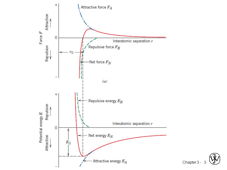
Attractive Energy: the energy released when the ions come close together
Repulsive energy: the energy absorbed as the ions come close together Net Energy: the sum of energies associated with the attraction and repulsion of the ions It is minimum when the ions are at their equilibrium separation distance r0. At the minimum energy, the force between the ions are zero. The ions will remain at an equilibrium separation distance r0 ( more stable).
.")
4
Energy and Packing • Non dense, random packing
typical neighbor bond length bond energy • Dense, ordered packing Energy r typical neighbor bond length bond energy Dense, ordered packed structures tend to 1.have lower energies and more stable energy arrangements. 2. Atoms come closer together and bond more tightly

5
Materials and Packing Si Oxygen Crystalline materials...
• atoms pack in periodic, 3D arrays • typical of: -metals -many ceramics -some polymers crystalline SiO2 Si Oxygen Noncrystalline materials... • atoms have no periodic packing • occurs for: -complex structures -rapid cooling "Amorphous" = Noncrystalline noncrystalline SiO2

6
Crystal: is a solids in which the constituent atoms, molecules, or ions are packed in a regularly ordered, repeating pattern extending in all three spatial dimensions. Long range order exist Noncrystalline(amorphous): materials that don’t crystallize, this long range atomic order is absent Crystal structure: it is the manner in which atoms, ions, or molecules are spatially arranged. Crystal system: is described in terms of the unit cell geometry. A crystal structure is described by both the geometry of, and atomic arrangements within the unit cell, whereas a Crystal system is described only in terms of the unit cell geometry. For example, face-centered cubic and body-centered cubic are crystal structures that belong to the cubic crystal system.
: materials that don’t crystallize, this long range atomic order is absent. Crystal structure: it is the manner in which atoms, ions, or molecules are spatially arranged. Crystal system: is described in terms of the unit cell geometry. A crystal structure is described by both the geometry of, and atomic arrangements within the unit cell, whereas a. Crystal system is described only in terms of the unit cell geometry. For example, face-centered cubic and body-centered cubic are crystal structures that belong to the cubic crystal system.")
7
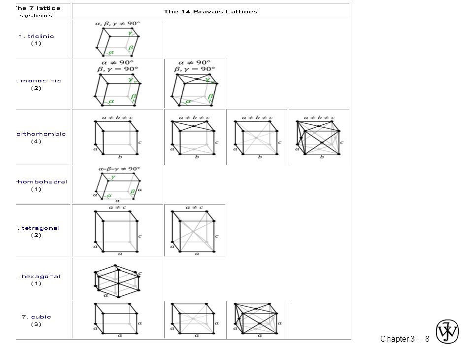
Crystal Systems Unit cell: smallest repetitive volume which contains the complete lattice pattern of a crystal. 7 crystal systems 14 crystal lattices a, b, and c are the lattice constants a, b, c, α, β, γ are lattice parameters

9
Section 3.4 – Metallic Crystal Structures
How can we stack metal atoms to minimize empty space? 2-dimensions vs. Now stack these 2-D layers to make 3-D structures

10
Metallic Crystal Structures
• Tend to be densely packed. • Reasons for dense packing: - Typically, only one element is present, so all atomic radii are the same. - Metallic bonding is not directional. - Nearest neighbor distances tend to be small in order to lower bond energy. - Electron cloud shields cores from each other • Have the simplest crystal structures. We will examine three such structures...

11
Simple Cubic Structure (SC)
• Rare due to low packing density (only Po has this structure) • Close-packed directions are cube edges. • Coordination # = 6 (# nearest neighbors)
 • Close-packed directions are cube edges. • Coordination # = 6. (# nearest neighbors)")
12
Atomic Packing Factor (APF)
Volume of atoms in unit cell* APF = Volume of unit cell *assume hard spheres • APF for a simple cubic structure = 0.52 close-packed directions a R=0.5a contains 8 x 1/8 = 1 atom/unit cell atom volume atoms unit cell 4 3 p (0.5a) 1 APF = 3 a unit cell volume
 1. APF = 3. a. unit cell. volume.")
13
Body Centered Cubic Structure (BCC)
• Atoms touch each other along cube diagonals. --Note: All atoms are identical; the center atom is shaded differently only for ease of viewing. ex: Fe (), Tantalum, Molybdenum • Coordination # = 8 2 atoms/unit cell: 1 center + 8 corners x 1/8
, Tantalum, Molybdenum. • Coordination # = 8. 2 atoms/unit cell: 1 center + 8 corners x 1/8.")
14
Atomic Packing Factor: BCC
• APF for a body-centered cubic structure = 0.68 a R a 3 a a 2 length = 4R = Close-packed directions: 3 a Adapted from Fig. 3.2(a), Callister 7e. APF = 4 3 p ( a/4 ) 2 atoms unit cell atom volume a
, Callister 7e. APF = p. ( a/4. ) 2. atoms. unit cell. atom. volume. a.")
15
Face Centered Cubic Structure (FCC)
• Atoms touch each other along face diagonals. --Note: All atoms are identical; the face-centered atoms are shaded differently only for ease of viewing. ex: Al, Cu, Pb, Ni, Ag • Coordination # = 12 4 atoms/unit cell: 6 face x 1/2 + 8 corners x 1/8

16
Atomic Packing Factor: FCC
• APF for a face-centered cubic structure = 0.74 a 2 a maximum achievable APF Close-packed directions: length = 4R = 2 a Unit cell contains: 6 x 1/2 + 8 x 1/8 = 4 atoms/unit cell APF = 4 3 p ( 2 a/4 ) atoms unit cell atom volume a
 atoms. unit cell. atom. volume. a.")
17
Hexagonal Close-Packed Structure (HCP)
• ABAB... Stacking Sequence • 3D Projection • 2D Projection c a A sites B sites Bottom layer Middle layer Top layer • Coordination # = 12 6 atoms/unit cell • APF = 0.74 ex: Cd, Mg, Ti, Zn • c/a = 1.633

18
CLOSE-PACKED CRYSTAL STRUCTURES FOR METALS
Both face-centered cubic and hexagonal close-packed crystal structures have atomic packing factors of 0.74, which is the most efficient packing of equal sized spheres or atoms. In addition to unit cell representations, these two crystal structures may be described in terms of close-packed planes of atoms (i.e., planes having a maximum atom or sphere-packing density); a portion of one such plane is illustrated in Figures bellow. Both crystal structures may be generated by the stacking of these close-packed planes on top of one another; the difference between the two structures lies in the stacking sequence.
; a portion of one such plane is illustrated in Figures bellow. Both crystal structures may be generated by the stacking of these close-packed planes on top of one another; the difference between the two structures lies in the stacking sequence.")
20
Theoretical Density, r A knowledge of crystal structure of a metallic solid permits computation density : Cell Unit of Volume Total in Atoms Mass Density = = VC NA n A = where n = number of atoms/unit cell A = atomic weight g/mole VC = Volume of unit cell = a3 for cubic NA = Avogadro’s number = x 1023 atoms/mol

21
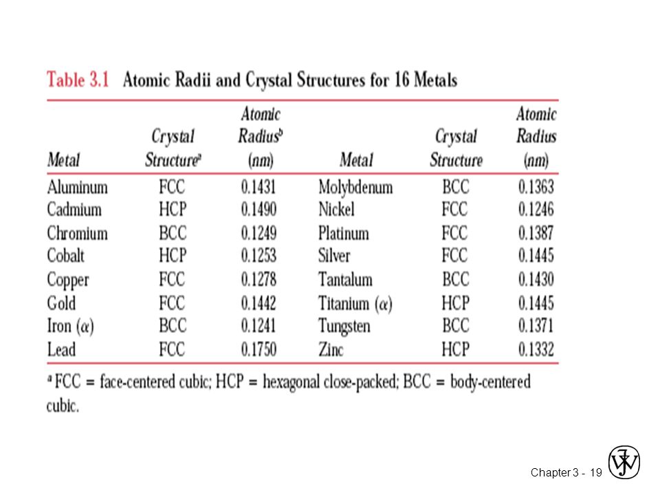
Theoretical Density, r = a R Ex: Cr (BCC) A = 52.00 g/mol
R = nm n = 2 a = 4R/ 3 = nm = a 3 52.00 2 atoms unit cell mol g volume 6.023 x 10²³ theoretical = 7.18 g/cm3 ractual = 7.19 g/cm3

22
Densities of Material Classes
In general Graphite/ r metals r ceramics r polymers Metals/ Composites/ > > Ceramics/ Polymers Alloys fibers Semicond 30 Why? Metals have... • close-packing (metallic bonding) • often large atomic masses 2 Magnesium Aluminum Steels Titanium Cu,Ni Tin, Zinc Silver, Mo Tantalum Gold, W Platinum *GFRE, CFRE, & AFRE are Glass, Carbon, & Aramid Fiber-Reinforced Epoxy composites (values based on 60% volume fraction of aligned fibers 10 in an epoxy matrix). G raphite Silicon Glass - soda Concrete Si nitride Diamond Al oxide Zirconia Ceramics have... • less dense packing • often lighter elements 5 3 4 (g/cm ) 3 Wood AFRE * CFRE GFRE* Glass fibers Carbon fibers A ramid fibers r H DPE, PS PP, LDPE PC PTFE PET PVC Silicone Polymers have... • low packing density (often amorphous) • lighter elements (C,H,O) 2 1 Composites have... • intermediate values 0.5 0.4 0.3
 • often large atomic masses. 2. Magnesium. Aluminum. Steels. Titanium. Cu,Ni. Tin, Zinc. Silver, Mo. Tantalum. Gold, W. Platinum. *GFRE, CFRE, & AFRE are Glass, Carbon, & Aramid Fiber-Reinforced. Epoxy composites (values based on. 60% volume fraction of aligned fibers. 10. in an epoxy matrix). G. raphite. Silicon. Glass. - soda. Concrete. Si nitride. Diamond. Al oxide. Zirconia. Ceramics have... • less dense packing. • often lighter elements (g/cm ) 3. Wood. AFRE. * CFRE. GFRE* Glass fibers. Carbon. fibers. A. ramid fibers. r. H. DPE, PS. PP, LDPE. PC. PTFE. PET. PVC. Silicone. Polymers have... • low packing density. (often amorphous) • lighter elements (C,H,O) Composites have... • intermediate values")
23
Single crystal For a crystalline solid, when the periodic and repeated arrangement of atoms is perfect or extends throughout the entirety of the specimen without interruption. All unit cells interlock in the same way and have the same orientation. Single crystals exist in nature, but they may also be produced artificially. They are ordinarily difficult to grow, because the environment must be carefully controlled.

24
POLYCRYSTALLINE MATERIALS
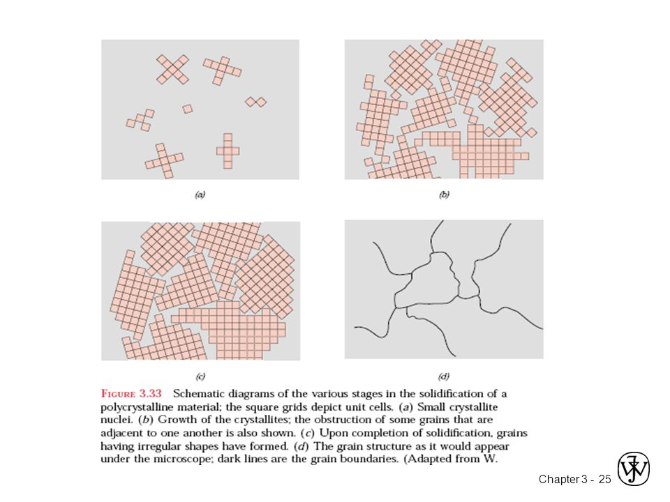
Most crystalline solids are composed of a collection of many small crystals or grains; such materials are termed polycrystalline The Various stages in the solidification of a polycrystalline specimen are: Initially, small crystals or nuclei form at various positions. The small grains grow by the successive addition from the surrounding liquid of atoms to the structure of each. The extremities of adjacent grains impinge on one another as the solidification process approaches completion exists some atomic mismatch within the region where two grains meet; this area, called a grain boundary

26
Crystals as Building Blocks
• Some engineering applications require single crystals: --diamond single crystals for abrasives --turbine blades • Properties of crystalline materials often related to crystal structure. --Ex: Quartz fractures more easily along some crystal planes than others.

27
Polycrystals Anisotropic
• Most engineering materials are polycrystals. 1 mm Isotropic • Each "grain" is a single crystal. • If grains are randomly oriented, overall component properties are not directional. • Grain sizes typ. range from 1 nm to 2 cm (i.e., from a few to millions of atomic layers).
.")
28
Single vs Polycrystals
E (diagonal) = 273 GPa E (edge) = 125 GPa • Single Crystals -Properties vary with direction: anisotropic. -Example: the modulus of elasticity (E) in BCC iron: • Polycrystals 200 mm -Properties may/may not vary with direction. -If grains are randomly oriented: isotropic. (Epoly iron = 210 GPa) -If grains are textured, anisotropic.
 = 273 GPa. E (edge) = 125 GPa. • Single Crystals. -Properties vary with. direction: anisotropic. -Example: the modulus. of elasticity (E) in BCC iron: • Polycrystals. 200 mm. -Properties may/may not. vary with direction. -If grains are randomly. oriented: isotropic. (Epoly iron = 210 GPa) -If grains are textured, anisotropic.")
29
Polymorphism Two or more distinct crystal structures for the same material (allotropy/polymorphism) ex. titanium , -Ti ex. carbon (cubic)diamond, (hexagonal)graphite BCC FCC 1538ºC 1394ºC 912ºC -Fe -Fe -Fe liquid Ex.iron system
diamond, (hexagonal)graphite. BCC. FCC. 1538ºC. 1394ºC. 912ºC. -Fe. -Fe. -Fe. liquid. Ex.iron system.")
30
CRYSTALLOGRAPHIC POINTS, DIRECT IONS AND PLANES
Crystallographic planes and directions are specified in terms of an indexing scheme. Crystallographic directional and planar equivalencies are related to atomic linear and planar densities, respectively. The atomic packing (i.e., planar density) of spheres in a crystallographic plane depends on the indices of the plane as well as the crystal structure.
 of spheres in a crystallographic plane depends on the indices of the plane as well as the crystal structure.")
31
Point Coordinates To specify the position of any point located within unit cell. z x y a b c 000 111 Point coordinates for unit cell center are a/2, b/2, c/ ½ ½ ½ Point coordinates for unit cell corner are 111 Translation: integer multiple of lattice constants identical position in another unit cell Lattice constants: a, b, c z 2c y b b

32
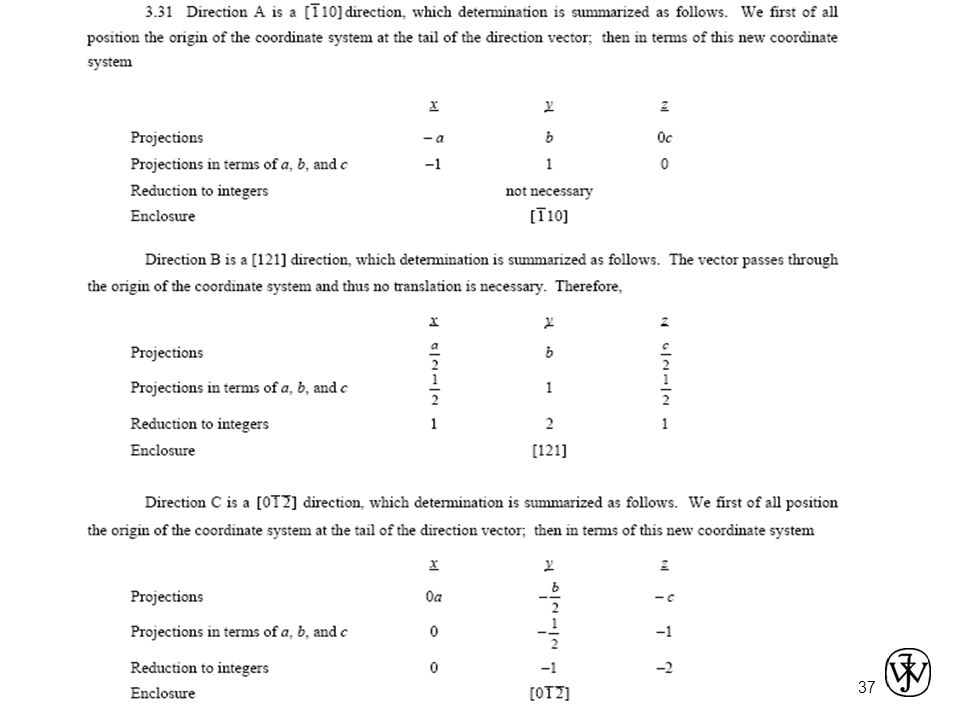
Crystallographic Directions
Is defined as a line between two points, or a vector. z Algorithm 1. Vector repositioned (if necessary) to pass through origin.( parallelism maintained) 2. Read off projections in terms of unit cell dimensions a, b, and c 3. Adjust to smallest integer values( multiplied or divided) 4. Enclose in square brackets, no commas [uvw] y x ex: 1, 0, ½ Lecture 2 ended here => 2, 0, 1 => [ 201 ] -1, 1, 1 where overbar represents a negative index [ 111 ] => families of directions <uvw>
 to pass. through origin.( parallelism maintained) 2. Read off projections in terms of unit cell dimensions a, b, and c 3. Adjust to smallest integer values( multiplied. or divided) 4. Enclose in square brackets, no commas. [uvw] y. x. ex: 1, 0, ½. Lecture 2 ended here. => 2, 0, 1. => [ 201 ] -1, 1, 1. where overbar represents a negative index. [ 111 ] => families of directions <uvw>")
33
For each of the three axes, there will exist both positive and negative coordinates. Thus negative indices are also possible, which are represented by a bar over the appropriate index. For example, the direction would have a component in the - y direction. Also, changing the signs of all indices produces an antiparallel direction; that is, is directly opposite to

34
Ex. The [100], [110], and [111] directions are common ones; they are drawn in the unit cell shown in Figure
![Ex. The [100], [110], and [111] directions are common ones; they are drawn in the.](http://slideplayer.com/slide/6922608/23/images/34/Ex.+The+%5B100%5D%2C+%5B110%5D%2C+and+%5B111%5D+directions+are+common+ones%3B+they+are+drawn+in+the..jpg "unit cell shown in Figure.")
35
Example

36
Example Draw a direction within a cubic unit cell.
SOLUTION First construct an appropriate unit cell and coordinate axes system. In the accompanying figure the unit cell is cubic, and the origin of the coordinate system, point O, is located at one of the cube corners. For this direction, the projections along the x, y, z axes are 1a, -1a, and 0a, respectively. This direction is defined by a vector passing from the origin to point P, which is located by first moving along the x axis a units, and from this position, parallel to the y axis a units, as indicated in the figure. There is no z component to the vector, since the z projection is zero.

38
Linear Density 3.5 nm a 2 LD = Linear Density LD = [110]
j a [110] ex: linear density of Al in [110] direction a = nm ½+1+ ½=2 atoms # atoms length 1 3.5 nm a 2 LD - = LD is important relative to the process of slip-the mechanism by which metals plastically deform
![Linear Density 3.5 nm a 2 LD = Linear Density LD = [110]](http://slideplayer.com/slide/6922608/23/images/38/Linear+Density+3.5+nm+a+2+LD+%3D+Linear+Density+%EF%82%BA+LD+%3D+%5B110%5D.jpg "j. a. [110] ex: linear density of Al in [110] direction a = nm. ½+1+ ½=2 atoms. # atoms. length nm. a. 2. LD. - = LD is important relative to the process of slip-the mechanism by which metals plastically deform.")
39
Crystallographic Planes

40
Crystallographic Planes
Miller Indices: Reciprocals of the (three) axial intercepts for a plane, cleared of fractions & common multiples. All parallel planes have same Miller indices. Algorithm 1. Read off intercepts of plane with axes in terms of a, b, c 2. Take reciprocals of intercepts 3. Reduce to smallest integer values 4. Enclose in parentheses, no commas i.e., (hkl)
 axial intercepts for a plane, cleared of fractions & common multiples. All parallel planes have same Miller indices. Algorithm 1. Read off intercepts of plane with axes in. terms of a, b, c. 2. Take reciprocals of intercepts. 3. Reduce to smallest integer values. 4. Enclose in parentheses, no. commas i.e., (hkl)")
41
Crystallographic Planes
z x y a b c example a b c Intercepts Reciprocals 1/ / / Reduction Miller Indices (110) example a b c z x y a b c Intercepts 1/ Reciprocals 1/½ 1/ 1/ Reduction Miller Indices (100)
 example. a b c. z. x. y. a. b. c. 1. Intercepts. 1/2 2. Reciprocals. 1/½ 1/ 1/ Reduction Miller Indices (100)")
42
Crystallographic Planes
z x y a b c example a b c Intercepts 1/ /4 Reciprocals 1/½ 1/ /¾ /3 Reduction Miller Indices (634)
")
43
Crystallographic Planes
We want to examine the atomic packing of crystallographic planes Iron foil can be used as a catalyst. The atomic packing of the exposed planes is important. Draw (100) and (111) crystallographic planes for Fe. b) Calculate the planar density for each of these planes.
 and (111) crystallographic planes. for Fe. b) Calculate the planar density for each of these planes.")
44
Planar Density of (100) Iron
Solution: At T < 912C iron has the BCC structure. 2D repeat unit R 3 4 a = (100) Radius of iron R = nm = Planar Density = a 2 1 atoms 2D repeat unit nm2 12.1 m2 = 1.2 x 10¹⁹ R 3 4 area
 Radius of iron R = nm. = Planar Density = a atoms. 2D repeat unit. nm m2. = 1.2 x R area.")
45
Planar Density of (111) Iron
Solution (cont): (111) plane 1 atom in plane/ unit surface cell 2 a atoms in plane atoms above plane atoms below plane 2D repeat unit 3 h = a 2 3 2 R 16 4 a ah area = ÷ ø ö ç è æ 1 = nm2 atoms 7.0 m2 0.70 x 10¹⁹ 3 2 R 16 Planar Density = 2D repeat unit area
: (111) plane. 1 atom in plane/ unit surface cell. 2. a. atoms in plane. atoms above plane. atoms below plane. 2D repeat unit. 3. h. = a R a. ah. area. = ÷ ø. ö. ç. è. æ. 1. = nm2. atoms m x R. 16. Planar Density = 2D repeat unit. area.")
46
X-Ray Diffraction Diffraction gratings must have spacings comparable to the wavelength of diffracted radiation. Can’t resolve spacings Spacing is the distance between parallel planes of atoms.

47
X-Rays to Determine Crystal Structure
• Incoming X-rays diffract from crystal planes. reflections must be in phase for a detectable signal spacing between planes d incoming X-rays outgoing X-rays detector q l extra distance travelled by wave “2” “1” “2” X-ray intensity (from detector) q c d = n l 2 sin Measurement of critical angle, qc, allows computation of planar spacing, d. n is the order of reflection Which may be any integer(1,2,3,…)
 q. c. d = n l. 2 sin. Measurement of critical angle, qc, allows computation of planar spacing, d. n is the order of reflection. Which may be any integer(1,2,3,…)")
48
X-Ray Diffraction Pattern
z x y a b c z x y a b c z x y a b c (110) (211) Intensity (relative) (200) Diffraction angle 2q Diffraction pattern for polycrystalline a-iron (BCC)
 (211) Intensity (relative) (200) Diffraction angle 2q. Diffraction pattern for polycrystalline a-iron (BCC)")
49
SUMMARY • Atoms may assemble into crystalline or amorphous structures.
• Common metallic crystal structures are FCC, BCC, and HCP. Coordination number and atomic packing factor are the same for both FCC and HCP crystal structures. • We can predict the density of a material, provided we know the atomic weight, atomic radius, and crystal geometry (e.g., FCC, BCC, HCP). • Crystallographic points, directions and planes are specified in terms of indexing schemes. Crystallographic directions and planes are related to atomic linear densities and planar densities.
. • Crystallographic points, directions and planes are. specified in terms of indexing schemes. Crystallographic directions and planes are related. to atomic linear densities and planar densities.")
50
SUMMARY • Materials can be single crystals or polycrystalline.
Material properties generally vary with single crystal orientation (i.e., they are anisotropic), but are generally non-directional (i.e., they are isotropic) in polycrystals with randomly oriented grains. • Some materials can have more than one crystal structure. This is referred to as polymorphism (or allotropy). • X-ray diffraction is used for crystal structure and interplanar spacing determinations.
, but are generally. non-directional (i.e., they are isotropic) in polycrystals. with randomly oriented grains. • Some materials can have more than one crystal. structure. This is referred to as polymorphism (or. allotropy). • X-ray diffraction is used for crystal structure and. interplanar spacing determinations.")
Similar presentations


 Why study this?>")


 Miller Indices Z X Y (100).>")


