Download presentation
Presentation is loading. Please wait.

1
RT 244 -12 Wk 14 Digital Artifacts & Imaging ERRORS
The advantages of CR are its large dynamic range, digital format, portability, and post-processing capability But not PERFECT –Imaging Errors can still occur See NOTES at bottom of slides for additional information Some information obtained from: AR Online » Current Issue » Artifacts and misadventures in digital radiography By Charles E. Willis, PhD, DABR; Stephen K. Thompson, MS, DABR; S. Jeff Shepard, MS, DABR Volume: 33 Number: 1 January 2004 New technologies should be developed for dealing with pediatric examinations and patients with prosthetic devices. New image processing strategies may be needed with these special patients, as well. Thorough training and active onsite support of the technical staff are crucial. For many, this is a completely different way of thinking about the imaging process. Technologists are generally eager to become involved and master this new technology, but they need proper training and guidance to use it effectively to produce diagnostic-quality images.

2
Artifacts Any irregularity on an image that is not caused by proper shadowing of tissue by the primary x-ray beam. Are undesirable optical densities or blemishes on a radiograph. Can be very interesting at times. You become the detective, what caused that?

3
CR artifacts require special attention.
This is due to the fact that CR artifacts may be produced from various components of the CR system itself Artifacts may also be generated by the users who are not aware of the proper imaging techniques or selection of appropriate image processing protocols Since CR is also very sensitive to scattered radiation, it is vital that anti-scattered grids be used as in conventional radiography. Radiographers should be concerned since these may generate unwanted artifacts that could not be corrected by any image processing algorithm.

4
Artifact Classification Review of Film/Screen

5
Artifact Classification Digital – CR & DR

6
OPTIMIZATION OF CR IMAGES
Quality of CR images Technologists are the key persons delivering good quality radiographs dose given to the patients. CR images can NOT always be adjusted after exposing CRITICAL to CR/DR Imaging is Technique, Positioning Collimation. The impression that CR images can always be adjusted after exposing the CR with x-rays is not necessarily true.

7
Image processing selection Lifetime of the PSP
Optimization of a CR image quality may be achieved by optimizing the following factors OBJECT ARTIFACTS: Positioning and collimation Exposure techniques Image processing selection Lifetime of the PSP

8
CR Artifacts Positioning errors Collimation errors
Backscatter radiation LUT selection/histogram

9
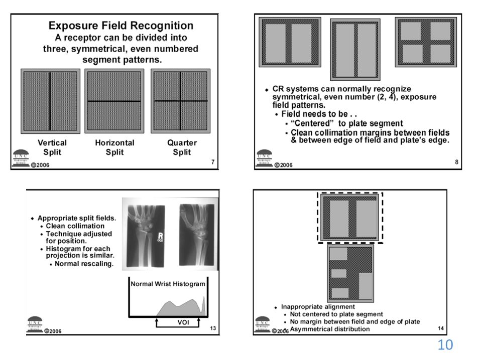
Positioning of Part/ Collimation
2 or more two projections on one IR Is not a good practice with CR technique, since double or multiple exposures on a single PSP) can lead to a failure of the image processing software to detect the image boundary. Matching the positioning and collimation with the image processing parameters is also crucial. Image processing will eventually fail to process since the input information is totally different. The F/S method of two projections of a hand radiograph in one 18 cm x 24 cm film. Is not a good practice with CR technique, since double or multiple exposures on a single photostimulable phosphor (PSP) can lead to a failure of the image processing software to detect the image boundary. Matching the positioning and collimation with the image processing parameters is also crucial.
 can lead to a failure of the image processing software to detect the image boundary. Matching the positioning and collimation with the image processing parameters is also crucial. Image processing will eventually fail to process since the input information is totally different. The F/S method of two projections of a hand radiograph in one 18 cm x 24 cm film. Is not a good practice with CR technique, since double or multiple exposures on a single photostimulable phosphor (PSP) can lead to a failure of the image processing software to detect the image boundary. Matching the positioning and collimation with the image processing parameters is also crucial.")
11
Errors in collimation can cause mistakes in detection of the boundary, with a dramatic loss of image contrast

13
Positioning Errors

14
Collimation Errors

16
Loss of contrast due to partitioning errors

18
Alignment Error: Same technique, different centering and collimation
Some radiographers may take a radiograph of a lumbosacral spine without collimation, thus making the radiograph looks more like an image of the Kidney-Ureter-Bladder (KUB) technique. Image processing will eventually fail to process since the input information is totally different. S# 592 S# 664
 technique. Image processing will eventually fail to process since the input information is totally different. S# 592. S# 664.")
20
2 on 24 X 30 Technique adjusted 2 on 24 X 30 Same technique Rescaling error.

21
Single field per plate - better
All DR systems have extremely wide latitude, which means that connected to a display system with a relatively narrow dynamic range, DR images have extremely low contrast. The primary purpose of image processing is to maximize the contrast of the part of the image that contains relevant clinical details. To do this, the DR system locates either the boundary of collimation or the border of the projected anatomy, and disregards details outside this boundary.

22
What is the problem?

23
Placement of gonadal shields is no longer trivial, but may adversely affect image quality.

24
Software to compensate for metal in patient

25
Same pt – what improved this image?

26
Acquiring good quality images
Regardless of the acquisition technology, good radiographic images can be produced only when certain fundamental requirements are met. Appropriate radiographic technique must be used, proper tube potential (kVp), beam current (mAs), source-to-image distance (SID), collimation, alignment of the X-ray central ray, and positioning of detector and subject for the specific anatomic projection.
, beam current (mAs), source-to-image distance (SID), collimation, alignment of the X-ray central ray, and positioning of detector and subject for the specific anatomic projection.")
27
Exposure techniques CR may be operated at a different film speed, and then optimizing the exposure technique accordingly. Existing CR has a speed similar to medium speed film-screen system ( ) while spatial resolution is still generally inferior Proper selection of an image processing algorithm specific to each type of x-ray examination is thus important. The technical skills of radiographers definitely play a crucial role in determining the quality of the radiographic image. In order to introduce CR as a replacement for film-screen technique, the common thinking is that it would be reasonable to adhere to the same exposure techniques to help the radiographers to adapt to the newer technology. But this is not necessarily the case. CR may be operated at a different film speed, and then optimizing the exposure technique accordingly. Existing CR has a speed similar to medium speed film-screen system (200) while spatial resolution is still generally inferior The idea of reducing radiation dose to patients when switching from screen-film system to CR may not always be valid. To keep the same signal to noise ratio, CR needs 20% more radiation exposure as we treat CR as medium speed film. Reduction of radiation dose to the patient will then results from reduction of reject rate due to poor exposure technique. As a result of poorer intrinsic spatial resolution of the PSP, radiographers need to make sure that when they set up exposure factors, i.e., the mA station from small focal spot should be selected when imaging bones or other high resolution required body parts. Some radiographers may still use too low kVp for chest radiographs. Employing a standard high kVp technique when the pre-set kVp range for image processing may be higher prevents optimization of the image quality.
 while spatial resolution is still generally inferior. Proper selection of an image processing algorithm specific to each type of x-ray examination is thus important. The technical skills of radiographers definitely play a crucial role in determining the quality of the radiographic image. In order to introduce CR as a replacement for film-screen technique, the common thinking is that it would be reasonable to adhere to the same exposure techniques to help the radiographers to adapt to the newer technology. But this is not necessarily the case. CR may be operated at a different film speed, and then optimizing the exposure technique accordingly. Existing CR has a speed similar to medium speed film-screen system (200) while spatial resolution is still generally inferior. The idea of reducing radiation dose to patients when switching from screen-film system to CR may not always be valid. To keep the same signal to noise ratio, CR needs 20% more radiation exposure as we treat CR as medium speed film. Reduction of radiation dose to the patient will then results from reduction of reject rate due to poor exposure technique. As a result of poorer intrinsic spatial resolution of the PSP, radiographers need to make sure that when they set up exposure factors, i.e., the mA station from small focal spot should be selected when imaging bones or other high resolution required body parts. Some radiographers may still use too low kVp for chest radiographs. Employing a standard high kVp technique when the pre-set kVp range for image processing may be higher prevents optimization of the image quality.")
28
Exposure factor “creep"
related to the wide exposure latitude of DR. noise in DR images exposed at one-fourth to one-half of the appropriate level. artifacts are generally not apparent until the exposure exceeds 10 times the appropriate level. Technologists avoid repeating an underexposed study by routinely increasing the radiographic technique. Thus, the potential for gross overexposure exists in DR. Image optical density (OD), the usual indicator of proper exposure, is arbitrary in DR. Managment of exposure factor in DR must rely on the value of a derived exposure indicator is a well-known phenomenon related to the wide exposure latitude of DR. Observers tend to complain about noise in DR images exposed at one-fourth to one-half of the appropriate level. On the other hand, artifacts are generally not apparent until the exposure exceeds 10 times the appropriate level. Technologists soon learn to avoid the unpleasant circumstance of repeating an underexposed study by routinely increasing the radiographic technique. Thus, the potential for gross overexposure exists in DR. Image optical density (OD), the usual indicator of proper exposure, is arbitrary in DR. Managment of exposure factor in DR must rely on the value of a derived exposure indicator, which itself is subject to interference. However, programs that monitor the exposure indicator have been shown to be effective in controlling exposure factor in DR.10
, the usual indicator of proper exposure, is arbitrary in DR. Managment of exposure factor in DR must rely on the value of a derived exposure indicator. is a well-known phenomenon related to the wide exposure latitude of DR. Observers tend to complain about noise in DR images exposed at one-fourth to one-half of the appropriate level. On the other hand, artifacts are generally not apparent until the exposure exceeds 10 times the appropriate level. Technologists soon learn to avoid the unpleasant circumstance of repeating an underexposed study by routinely increasing the radiographic technique. Thus, the potential for gross overexposure exists in DR. Image optical density (OD), the usual indicator of proper exposure, is arbitrary in DR. Managment of exposure factor in DR must rely on the value of a derived exposure indicator, which itself is subject to interference. However, programs that monitor the exposure indicator have been shown to be effective in controlling exposure factor in DR.10.")
29
Errors in the selection of the anatomic projection can cause inappropriate processing

30
Wrong Algorithm Proper selection of an image processing algorithm specific to each type of x-ray examination is thus important. The technical skills of radiographers definitely play a crucial role in determining the quality of the radiographic image. Processing algorithms used by the DR system must be designed to anticipate the use of this display function in order to properly render the image for display. Not all vendors adhere to this standard. Calibrated, high-quality QC monitors are essential on every acquisition system and QC workstation. Adjusting image processing on an uncalibrated monitor leads to unsatisfactory images.

31
Over/Under Exposed Even though a CR image may be adjusted to improve the image visibility in the cases of over- or under-exposures, it would still be impossible for an image processing to improve the visibility of clinical features that were not available in the raw image.

35
Example of artifacts in CR an image with loss of contrast as a result of improper selection of image processing; the same image now shows acceptable image quality as a result of proper selection of image processing. proper adjustment of exposure technique is therefore still crucial in any radiography practice. Although an increased radiation exposure would yield a higher signal-to-noise ratio and better low contrast detectability in PSP, this would clearly violate the “As low as Reasonably Achievable” (ALARA) principle.
 principle.")
38
Too many X-rays are a disservice to the patient and may also produce poor images (Figure 3).
.")
39
Whether from underexposure or misalignment of a scatter reduction grid, too few X-rays produce noisy images The detector must receive enough X-rays to make a good image. Although DR is more tolerant of incorrect exposure factor selection, it cannot make up for extra noise, loss in subject contrast, and signal out of its range of adjustment.

40
Different exam parameters in different rooms

41
Double exposure is a classic operator error
that constitutes approximately 2% of all rejected images. The consequence of double exposure can be either a single repeated examination, when an inanimate object is involved (Figure 11), or two repeated examinations when two patients are involved (Figure 12). In DR, double exposures can also be caused by power interruptions and communications errors, as well as by inadequate erasure secondary to overexposure or erasure mechanism failure.
, or two repeated examinations when two patients are involved (Figure 12). In DR, double exposures can also be caused by power interruptions and communications errors, as well as by inadequate erasure secondary to overexposure or erasure mechanism failure.")
42
Double exposure (Figure 11),
,")
43
Double exposure # 12

44
Abdomen not cleared completely before chest
Used large cassette to balance small for patella on merchant board

45
#8

46
Edge Enhancement The secondary function of image processing is to customize contrast in the region of interest This type of image processing includes modifying the image to enhance the contrast and sharpness of some features while compromising the contrast and sharpness of others, as well as modifying the image to make it appear more like a conventional film. This secondary image processing is applied in a manner that is usually specific to the anatomic projection.

47
standard image edge sharpening

48
Halo effect with Edge enhancement

50
Post Processing An auxiliary purpose of image processing is to improve the usability of the digital image. This includes imprinting demographic overlays, adding annotations, applying borders and shadow masks, flipping and rotating, increasing magnification, conjoining images for special examinations like scoliosis, and modifying the sequence of views. This processing may require a separate QC workstation

52
IR Artifact - Digital Pixel Failure = CR & DR plates should last for thousands of exposures. Interpolation can be used to fix defects in a small area. Ghosting artifacts = exposure to environmental radiation or incomplete erasure.

53
background radiation

54
Image Receptor Artifacts
Debris on image receptor in DR can be confused with foreign bodies

55
Image Receptor Artifacts
Line caused from dirt collected in a CR Reader

56
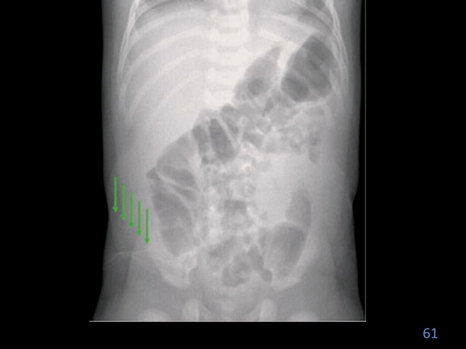
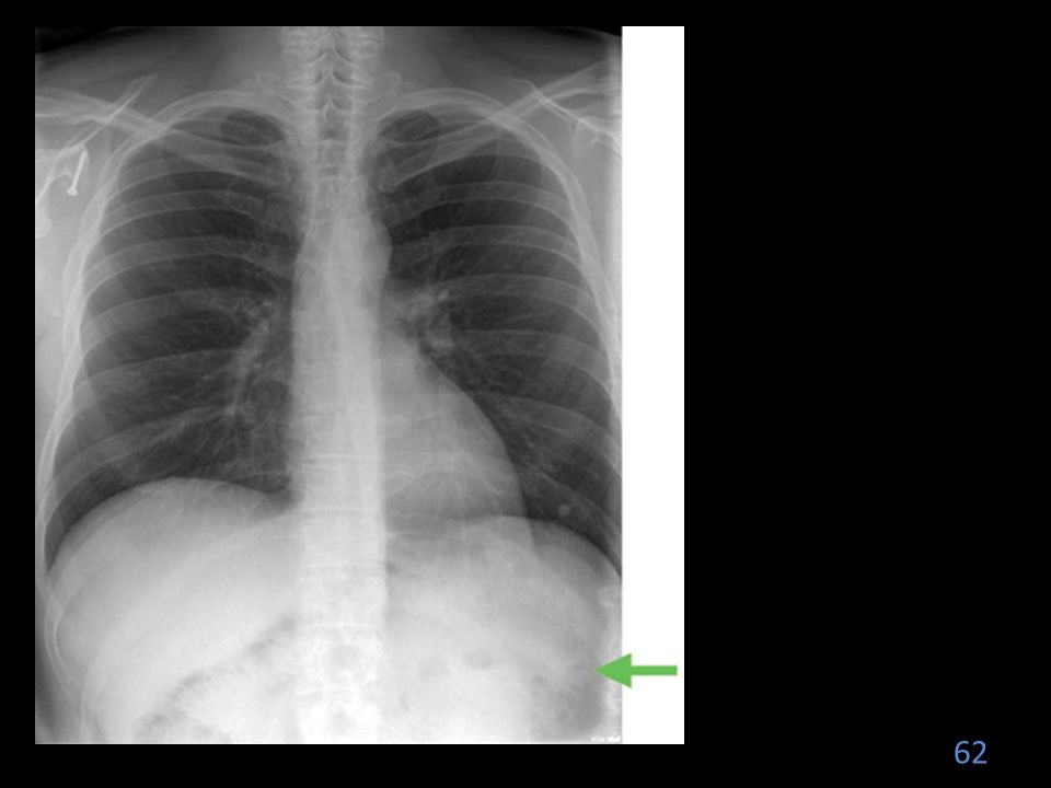
imaging plate was not fully erased before the chest examination was performed

57
Dirt on screens

58
#9

63
Lifetime of the PSP One of the major advantages of CR is that the phosphor plate is reusable. However, there are a number of factors that may affect the lifetime of an imaging plate. The plates are subjected to normal wear and tear from scratches, scuffs, cracks, and contamination with dust and dirt, which may interfere with the production of a good image. The establishment of a well-organized quality control program will play an important role in assessing the clinical quality of the imaging plate. This may easily be carried out by artifact assessment and uniformity evaluation across the plate.

64
Software Artifacts

65
Processing Errors

66
Digital Radiography Image Sampling
Image sampling, the plate is scanned, and the image’s location and its orientation are determined. The size of the signal is then determined, and a value is placed on each pixel. A histogram is generated from the image data. The raw data used to form the histogram are compared with a “normal” histogram of the same body part by the computer.

67
The Nyquist Theorem States that when sampling a signal (such as the conversion from an analog to a digital image), the sampling frequency must be greater than twice the bandwidth of the input signal so that the reconstruction of the original image will be nearly perfect. At least twice the number of pixels needed to form the image must be sampled. If too few pixels are sampled, the result will be a lack of resolution.
, the sampling frequency must be greater than twice the bandwidth of the input signal so that the reconstruction of the original image will be nearly perfect. At least twice the number of pixels needed to form the image must be sampled. If too few pixels are sampled, the result will be a lack of resolution.")
68
Aliasing & Grid errors = Moiré
Spatial frequency is greater than the Nyquist frequency a wraparound image is produced moiré effect Stationary Grids: grid lines and the scanning laser are parallel moiré effect

69
Moiré effect

70
Software Artifacts Image Compression – Used with teleradiology.
Compression techniques “lossless” or “lossy”

71
Image Compression Lossless compression: image can be reconstructed to be exactly the same as the original image. Compressed 10% or 50%. Lossy compression: image is compressed 100:1. Used only when fine detail is not required. Not useful for medical imaging.

72
Image Compression

73
Wider dynamic range means that technologists have to pay attention to exposure indicator values, instead of brightness and contrast. Without this attention, patient dose will escalate. If exposure indicator logs are available, they need to be evaluated. If they aren't, this will need to be done manually.

74
Misuses of image processing include
compensating for inappropriate radiographic technique, compensating for poor calibration of acquisition and display devices, and surreptitious deletion of nondiagnostic images. Image processing to recover nondiagnostic images to prevent re-exposure should be a last resort, not a routine activity. Routine reprocessing indicates a problem with automatic image processing or technical practice. Access to image-processing software is essential to develop and maintain appropriate processing parameters

Similar presentations