Download presentation
Presentation is loading. Please wait.

6
Chapter10 Refrigeration Cycle

7
10-1 Vapor-Compression Cycle 10-1-1 The Reversed Carnot Cycle T s 4 1 2 3 THTH TLTL Coefficient of Performance

8
Disadvantages Process 2-3 is difficult to be Fulfill in compressor Process 4-1 will do harm to turbine

9
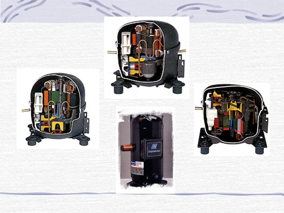
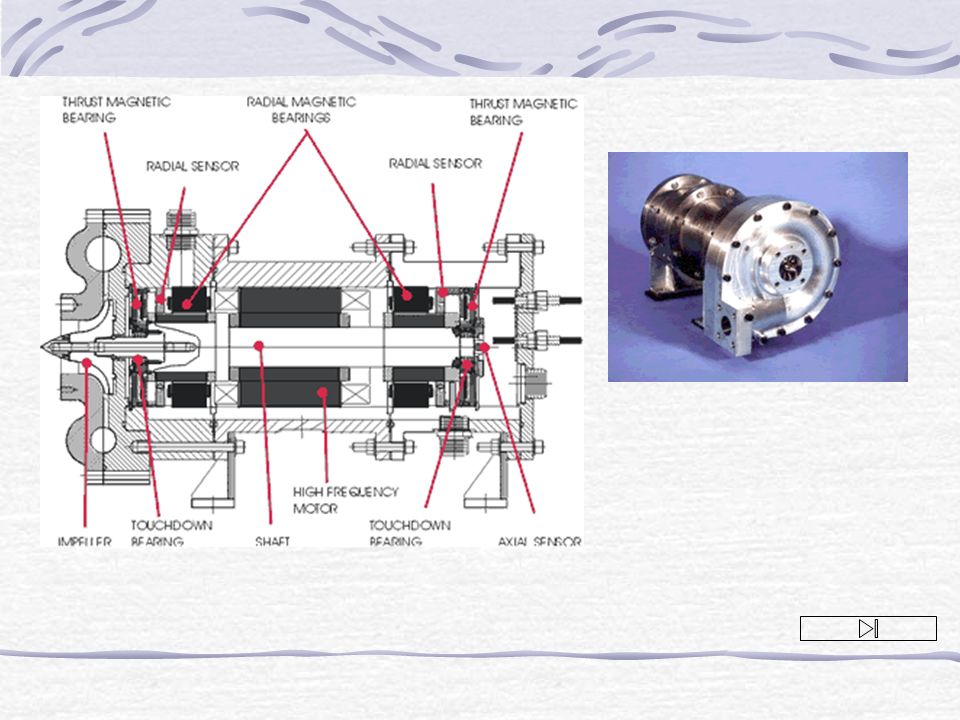
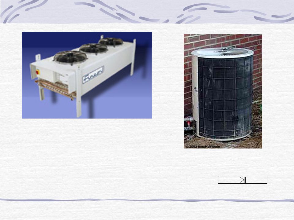
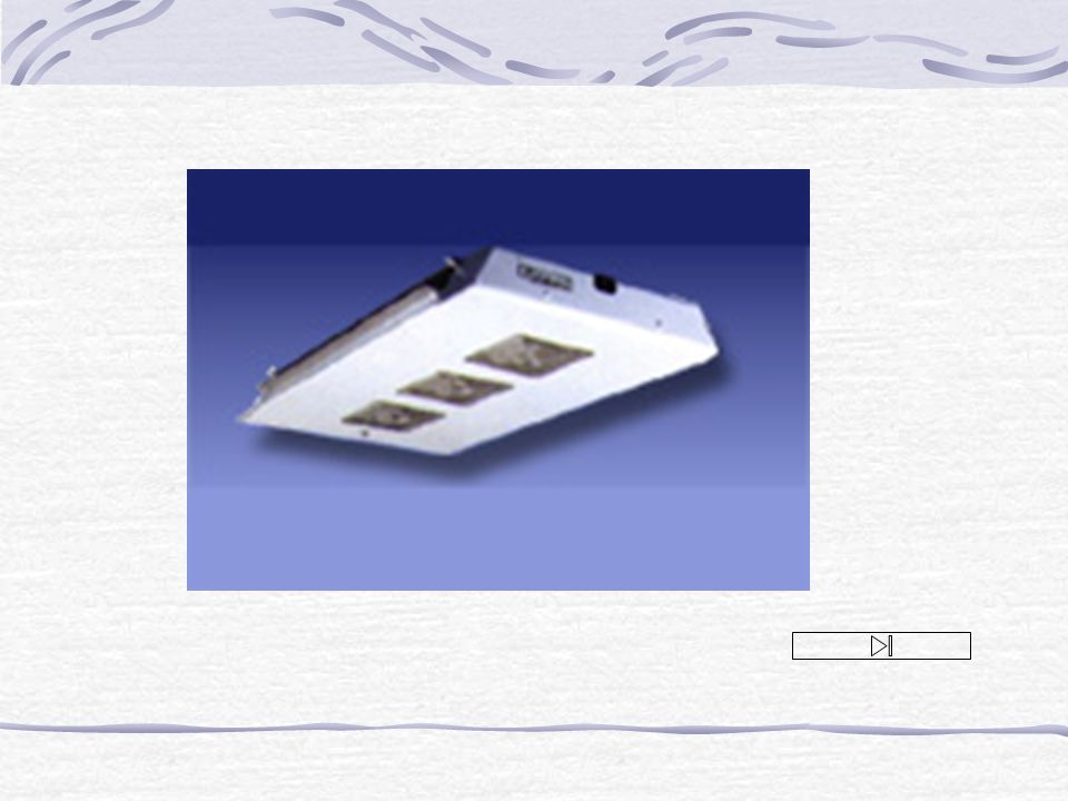
10-1-2 The Ideal Vapor-Compression Refrigeration Cycle condenser Equipments: 1 2 3 4 compressor Expansion valve evaporator

10
T s THTH TLTL 1 2 3 4

11
condenser compressor evaporator Capillary tube

13
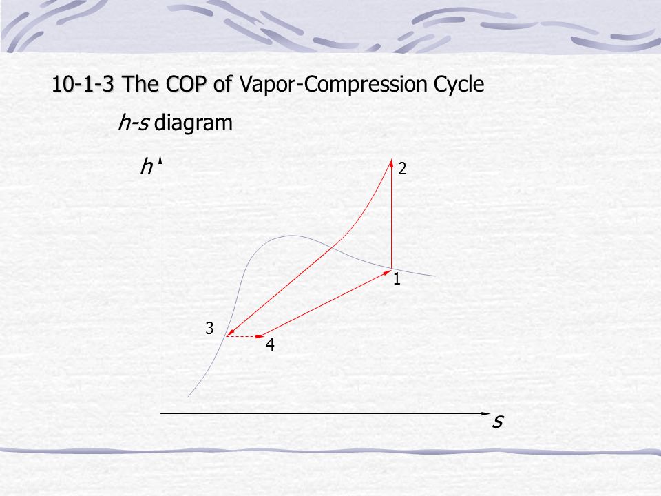
10-1-3 The COP of 10-1-3 The COP of Vapor-Compression Cycle h-s diagram h s 1 23 4

14
Usually p 1, p 2 are available h s 1 2 3 4 From p 1, get h 1 ”, s 1 ” h 1 = h 1 ” s 1 = s 1 ” From p 2, s 1, get h 2 From p 2, get h 2 ’ h 3 = h 2 ’ h 4 = h 3

15
p-h diagram

16
p h 1 2 3 4

17
10-2 Refrigerant Ammonia CFC(chlorofluorocarbons) water Good refrigerant High enthalpy of vaporization Not too low evaporator pressure Not too high condenser pressure Nontoxic Noncorrosive Chemically stable Low cost
 water Good refrigerant High enthalpy of vaporization Not too low evaporator pressure Not too high condenser pressure Nontoxic Noncorrosive Chemically stable Low cost")
18
10-3 Heat Pump An equipment Absorbing heat from environment for heating purpose T s THTH T0T0 1 2 3 4

19
Heat pump for heating

20
Heat pump for refrigeration

21
10-4 Innovative Vapor-compression Refrigeration Systems 10-4-1 Regenerative Vapor Compression cycle Equipments condenser evaporator Heat exchanger separator compressor

22
T s THTH TLTL 1 2 3 4 T-s Diagram 2’ 1’

23
10-4-2 Cascade Refrigeration Systems condenser evaporator

24
T s T0T0 T-s Diagram

25
10-4-3 Multistage Compression Refrigeration Systems condenser evaporator Flash chamber 1 2 3 heat exchanger 45 6 7 8 9 T s 1 2 3 4 5 6 7 8 9

26
10-4-4 Multipurpose Refrigeration Systems with a Single Compressor condenser Freezer refrigerator 1 2 3 4 5 6 Alternative path T s 1 2 3 4 5

27
10-4-5 Liquefaction of Gas Heat exchanger Make up gas Liquid removed Multistage compressor 1 2 3 4 5

28
T s 1 2 1 3 4 5

29
10-5 Gas Refrigeration cycle 10-4-1 Equipments Heat exchanger QHQH QLQL compressor turbine

30
T s p2p2 p1p1 1 2 3 4 T0T0 TLTL

31
10-4-2 COP of Gas Refrigeration Cycle T s 1 2 3 4 T0T0 TLTL

32
T s 1 2 3 4 T0T0 TLTL

33
Since To decrease compression ratio can increase COP To To decrease compression ratio will decrease power ratio

34
T s T0T0 TLTL

35
T s T0T0 TLTL 1 2 45 3 q 6 q 10-4-3 Regenerative Gas Refrigeration Cycle

36
Heat exchanger QHQH QLQL compressor turbine regenerator 1 2 3 45 6

37
10-6 Absorption Refrigeration System heat condenser evaporator =compressor

38
Refrigerant: Ammonia Transport medium: Water Refrigerant: Water Transport medium: Lithium bromide

39
10-6 Adsorption Refrigeration Solar energy Active carbon evaporator condenser

40
Cooling Tube Solar energy Night Cold air Active carbon Vacuum tube Cooling tower

41
The End of This Chapter Thank You

Similar presentations