Download presentation
Presentation is loading. Please wait.

1
Chapter 33 Alternating Current Circuits CHAPTER OUTLINE 33.1 AC Sources 33.2 Resistors in an AC Circuit 33.3 Inductors in an AC Circuit 33.4 Capacitors in an AC Circuit 33.5 The RLC Series Circuit 33.6 Power in an AC Circuit 33.7 Resonance in a Series RLC Circuit

2
33.1 AC Sources where Δ V max is the maximum output voltage of the AC source, or the voltage amplitude. The angular frequency of the AC voltage is

3
33.2 Resistors in an AC Circuit

4
The instantaneous voltage across the resistor is for a sinusoidal applied voltage, the current in a resistor is always in phase with the voltage across the resistor.

5
The rms current is

6
The average power delivered to a resistor that carries an alternating current is

7
Example 33.1 What Is the rms Current?

8
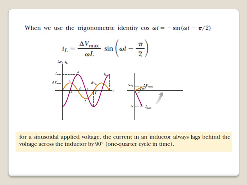
33.3 Inductors in an AC Circuit

10
we define ωL as the inductive reactance: so

11
the instantaneous voltage across the inductor is

12
Example 33.2 A Purely Inductive AC Circuit In a purely inductive AC circuit, L = 25.0 mH and the rms voltage is 150 V. Calculate the inductive reactance and rms current in the circuit if the frequency is 60.0 Hz.

13
33.4 Capacitors in an AC Circuit The voltage across the capacitor: The instantaneous current in the circuit:

14
The maximum current capacitive reactance the instantaneous voltage across the capacitor

15
Example 33.3 A Purely Capacitive AC Circuit ω=2 πf =377 s -1

16
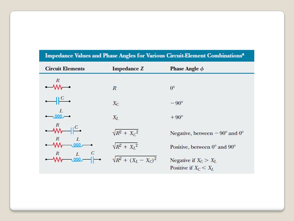
The maximum voltage values across the elements: the current at all points in a series AC circuit has the same amplitude and phase. The instantaneous applied voltage is 33.5 The RLC Series Circuit

17
The phase angle ϕ between the current and the voltage is impedance

19
Example 33.5 Analyzing a Series RLC Circuit

21
The instantaneous voltages across the three elements as

22
1- A 10-μF capacitor is plugged into a 110 V-rms 60-Hz voltage source, with an ammeter in series. What is the rms value of the current through the capacitor? a. 0.202 A (rms) b. 0.415 A (rms) c. 0.626 A (rms) d. 0.838 A (rms) e. 0.066 A (rms) 2- If an R = 1-k Ω resistor, a C = 1-μF capacitor, and an L = 0.2-H inductor are connected in series with a V = 150 sin (377t) volts source, what is the maximum current delivered by the source? a. 0.007 A b. 27 mA c. 54 mA d. 0.308 A e. 0.34 A
 b A (rms) c A (rms) d A (rms) e A (rms) 2- If an R = 1-k Ω resistor, a C = 1-μF capacitor, and an L = 0.2-H inductor are connected in series with a V = 150 sin (377t) volts source, what is the maximum current delivered by the source. a A b. 27 mA c. 54 mA d A e A.")
23
33.6 Power in an AC Circuit The instantaneous power P The average power delivered by the source is converted to internal energy in the resistor No power losses are associated with pure capacitors and pure inductors in an AC circuit If

24
Example 33.6 Average Power in an RLC Series Circuit Calculate the average power delivered to the series RLC circuit described in Example 33.5.

25
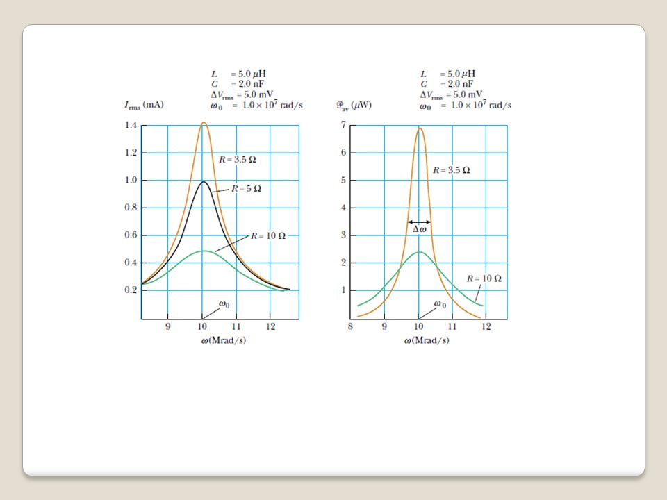
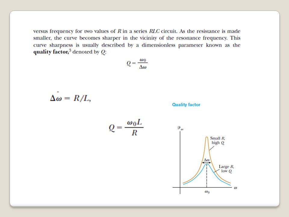
33.7 Resonance in a Series RLC Circuit

28
Example 33.7 A Resonating Series RLC Circuit

Similar presentations


>")
