Download presentation
Presentation is loading. Please wait.

1
Particle Control Technologies
Lecture notes adapted from Prof. Dr. Benoit Cushman-Roisin Thayer School of Engineering at Dartmouth

2
Design Criteria Design of a system which remove solid or liquid particulate matter from a gaseous medium Chacacteristics of gaseous medium and particulate matter to consider in the design: Size T,P,Q, Chem. Composition Chem. Composition Resistance Pressure Drop PM Control Device

3
Collection Efficiency
Considering the wide range of size of particulates, efficiency will be different for each size. The overall efficiency (h) can be calculated on a basis of total number (or mass) of particles Generally regulations are written based on mass, and efficiencies are calculated on mass basis.
 can be calculated on a basis of total number (or mass) of particles. Generally regulations are written based on mass, and efficiencies are calculated on mass basis.")
4
Collection Efficiency
Efficiencies calculated on mass basis: h: overall collection efficiency (fraction) Mi: total mass input rate (g/s or equivalent) Me: total mass emission rate (g/s or equivalent) Li: particulate loading in the inlet gas to the device (g/m3) Le:particulate loading in the exit gas stream, (g/m3)
 Mi: total mass input rate (g/s or equivalent) Me: total mass emission rate (g/s or equivalent) Li: particulate loading in the inlet gas to the device (g/m3) Le:particulate loading in the exit gas stream, (g/m3)")
5
Collection Efficiency
When the particulate size distribution is known, and the efficiency of the device is known as a function of particle size, the overall collection efficiency can be calculate: where hj: collection efficiency for the jth size mj: mass percent of particles in the jth size

6
Example 3.1 from the book

7
PM Control Devices Gravity Settler Cyclones ESP Filters and Baghouses
Wet Scrubbers

8
Settling Chamber Efficient for particles with diameter of mm (depending on its density) Velocity through chamber < m/s (to prevent reentrainment) V H L
 V. H. L.")
9
Settling Chamber Settling time < transit time through chamber
v H L Settling time < transit time through chamber t = H/vt = L/v Settling chambers are cheap to build and operate but not preferred due to their large space requirement

10
Settling Chamber Dp (um) Vt (m/s) Required Area 0.1 8.6 (10)-7 3 km2
Assuming unit density sphere at STP, vt and chamber Lw are tabulated below: Assumed flow rate Q = 150 m3/min Dp (um) Vt (m/s) Required Area 0.1 8.6 (10)-7 3 km2 0.5 1.0 (10)-5 0.25 km2 1.0 3.5 (10)-5 71000 m2 5 7.8 (10)-4 3200 m2 10 3.1 (10)-3 810 m2
 Vt (m/s) Required Area (10)-7. 3 km (10) km (10) m (10) m (10) m2.")
11
Settling Chamber Baffled Settling Chamber
Large particles can not make sudden direction change and settle into dead space of chamber Baffle chambers are used as precleaners

12
Cyclones :

13
Cyclones :

14
Cyclone Geometry

15
Cyclone Geometry

16
Cyclone Theory

17
Cyclone Theory

18
Cyclone Theory

19
Cyclone Theory

20
Collection Efficiency

21
Collection Efficiency
(i) increase Vt (expensive, since DP a Vt2, as we will see in the next slides
 increase Vt (expensive, since DP a Vt2, as we will see in the next slides.")
22
Collection Efficiency

23
Collection Efficiency

24
Pressure Drop K: a constant depends on cyclone configuration and operating conditions. Theoretically K can vary considerably but for air pollution work with standard tangential-entry cyclones values of K are in the range of 12 to 18 Cyclone pressure drops range from about 0.5 to 10 velocity heads (250 to 4000 Pa)
")
25
Cyclone Analysis

26
Example

27
Example Conventional Type (No:3) N=(1/H) (Lb+Lc/2) = (1/0.5)(2+2/2)=6
Vi=Q/WH =150 /(0.25*0.5) =1200 m/min 20 Vi=20 m/s
 =1200 m/min 20. Vi=20 m/s.")
28
Example Calculate efficiency for each size range witch dpc = 5.79 um:

29
Example 4.5

30
Example 4.5

31
Example 4.5

32
ESP

33
ESP

35
ESP Geometry

36
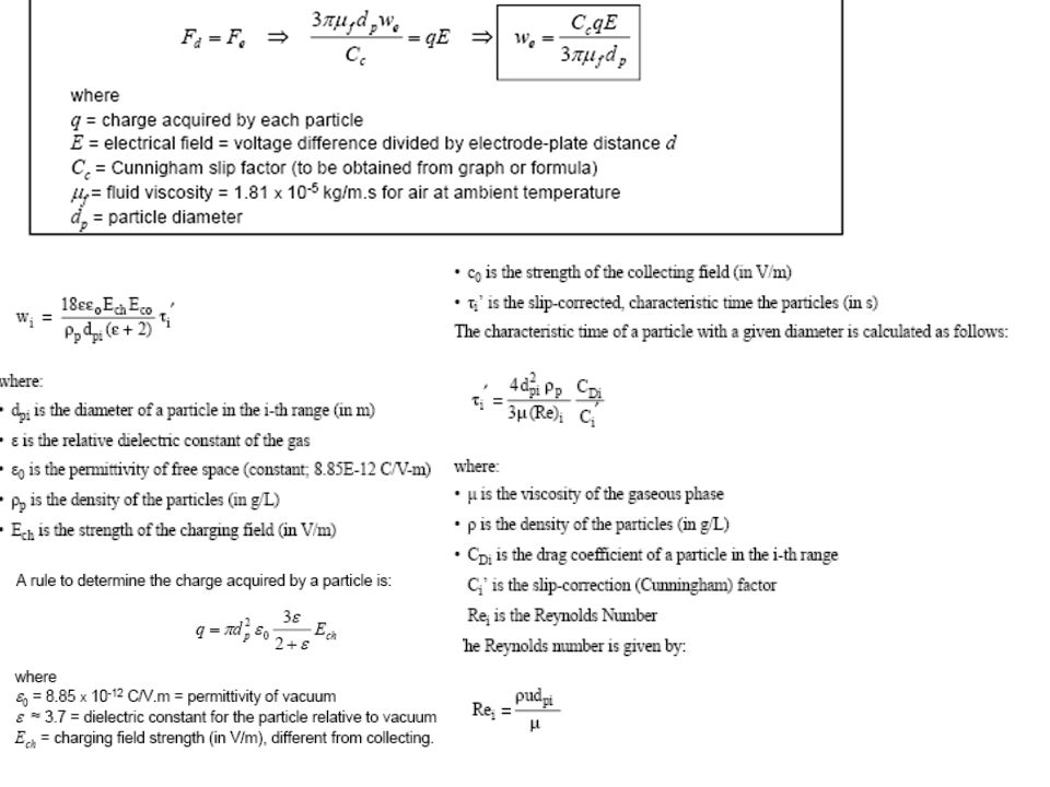
ESP Theory

37
Corona Power vrs Efficiency

38
ESP Theory

39
ESP THEORY

40
ESP Theory

41
ESP Theory

42
ESP Theory

43
ESP Theory

44
ESP Theory

45
ESP Theory

46
ESP Theory

47
ESP Theory

48
ESP Theory

49
Efficiency

50
Efficiency

51
Effect of Resistivity

52
Resistivity Resistivity (P) is resistance to electrical conduction and can vary widely P of a material is determined experimentally by establishing a current flow through a slab (of known geometry) of the material P = (RA/L)=(V/i)(A/L) [ohm-cm] R:resistance, ohm A: area normal to the current flow, cm2 L:path length in the direction of current flow, cm, V: voltage, i: current, A
 of the material. P = (RA/L)=(V/i)(A/L) [ohm-cm] R:resistance, ohm. A: area normal to the current flow, cm2. L:path length in the direction of current flow, cm, V: voltage, i: current, A.")
53
Resistivity

54
Resistivity

55
Sparking

56
Internal Configuration
Internal configuration design is more art than science The even distribution of gas flow through the ducts is very important to the proper operation of an ESP The number of ducts (Nd) is equal to one less than the number of plates (n-1) Nd = Q/uDH (eq 5.15) u: linear gas velocity (m/min) D Channel width (plate separation), m H: plate height, m
 is equal to one less than the number of plates (n-1) Nd = Q/uDH (eq 5.15) u: linear gas velocity (m/min) D Channel width (plate separation), m. H: plate height, m.")
57
Internal Configuration
At the start of the design, use 5.15 to estimate Nd by assuming a value for H and choosing representative values of u and D

58
Typical Values for the Fly-Ash ESP
Parameter Range of Values Drift velocity 1-10 m/min Channel (Duct) Width, D 15-40 cm Specific Collection Area Plate area/Gas Flow m2/(m3/min) Gas velocity u m/s Aspect Ratio (R) Duct Length/Plate Height Corona Power Ratio Pc/Q W/(m3/min) Corona Current Ratio (Ic/A) mA/m2 Plate area per electrical set As m2 Number of electrical sections 2-6 Table 5.1
 Width, D cm. Specific Collection Area Plate area/Gas Flow m2/(m3/min) Gas velocity u m/s. Aspect Ratio (R) Duct Length/Plate Height Corona Power Ratio Pc/Q W/(m3/min) Corona Current Ratio (Ic/A) mA/m2. Plate area per electrical set As m2. Number of electrical sections Table 5.1.")
59
Internal Configuration
The overall length of the precipitator (Lo) Lo=NsLp + (Ns-1)Ls + Len +Lex Lp:: length of plate Ls: spacing between electrical sections ( m) Len: entrance section in length (several meters) Lex:exit section in length (several meters) Ns: number of mechanical fields Ns ranges between 2 and 6. Ns=RH/Lp R is the aspect ratio
 Lo=NsLp + (Ns-1)Ls + Len +Lex. Lp:: length of plate. Ls: spacing between electrical sections ( m) Len: entrance section in length (several meters) Lex:exit section in length (several meters) Ns: number of mechanical fields. Ns ranges between 2 and 6. Ns=RH/Lp R is the aspect ratio.")
60
Internal Configuration
When the numbers of ducts and sections have been specified, the actual collection area (Aa) can be calculated as: Aa=2HLpNsNd During the design process several plate sizes and numbers of ducts are tried until one combination is found such that Aa is equal to the required collection area.
 can be calculated as: Aa=2HLpNsNd. During the design process several plate sizes and numbers of ducts are tried until one combination is found such that Aa is equal to the required collection area.")
61
Collection Efficiency vrs Particle Diameter

62
An Example

63
Example

64
Example

65
POWER REQUIREMENT

66
POWER REQUIREMENT k: an adjustable constant in the range of for we in ft/sec and Pc/A in W/ft2

68
Problem 5.10 Provide a reasonable design for a 99.4% efficient ESP treating 30,000 m3/min of gas. The dust has a resistivity of 7.1 (10)10 ohm-cm. Specify the total plate area, channel width, number and size of plates, number of electrical sections (total and in the direction of flow), and total corona power to be supplied, and estimate the overall dimensions.
10 ohm-cm. Specify the total plate area, channel width, number and size of plates, number of electrical sections (total and in the direction of flow), and total corona power to be supplied, and estimate the overall dimensions.")
69
SOLUTION

70
SOLUTION

71
SOLUTION

72
SOLUTION

74
Video Demonstration on Electrostatic Precipitation

Similar presentations


 - Prof. Vinod Jindal>")
