Download presentation
Presentation is loading. Please wait.

1
Welcome

3
OPTIONS in POWER GENERATION

4
SERVING CORE & INFRASTRUCTURE SECTORS OF THE ECONOMY
Operating Business Areas Power Thermal Sub-Crit: Up to 600MW Sup. Crit: 660 & 800MW Boilers, STG, Auxiliaries, ESP EPC Hydro Up to 250 MW Turbines, Generators Controls Gas Adv. Class GTs Open Cycle, Combined Cycle Nuclear Up to 1000 MWe Power Transmission Switchgear, Transformers, Insulators, Substations, SCADA, HVDC Systems Industry Captive Power Plants Boilers, STGs, Auxiliaries, C&I Systems, DG Transportation Locomotives (electric - AC/DC), Diesel-electrics, EMU's, Traction Electrics Other Products On-Shore Oil Rigs, Compressors, NCES, Desalination Plants, Valves, Motors International Operations SERVING CORE & INFRASTRUCTURE SECTORS OF THE ECONOMY 4
, Diesel-electrics, EMU s, Traction Electrics. Other Products. On-Shore Oil Rigs, Compressors, NCES, Desalination Plants, Valves, Motors. International Operations. SERVING CORE & INFRASTRUCTURE SECTORS OF THE ECONOMY. 4.")
5
BHEL’S Contribution to Indian Power Sector
Practically every 3 houses out of 4 in India are supplied power, generated from BHEL sets Over 1,15,000 MW added by BHEL in domestic and international segments 5 5

6
Steam Generators Exported
Customer Unit Size No EEA-Egypt Al-Arish TPS 12 T/h 1 ECT-Libya Tripoli West TPS 45 T/h 2 PT IBR-Indonesia Bharat Rayon 75 / 80 T/h 3 / 3 PT – IBR Jawa bharat Indonesia 120 T/h PT. ADARO Indoesia 126 T/h KONIAMBO-Nickel SAS Koniambo Nickel SAS – New Caledonia 405 T/h NEB-Malaysia Sultan Ismail TPS 30 MW Tuanku Jaafar TPS 60 MW 120 MW 3 Prai TPS Pasirgudang TPS NEC-Sudan Kosti TPS 125 MW 4 MAYLAN Intra Ltd Senegal / Africa PEEGT Tishreen,Syria 200 MW Total 36

7
Trend in unit sizes & Cycle parameters
SHO Pressure (kg/cm2(a) SHO/RHO Temperature (Deg.C) Year of Introduction 60 / 70 MW 96 540 1965 110 / 120 MW 139 540/540 1966 200 / 210 MW 137 / 156 1972 250 MW 156 1991 500 MW 179 540/568 1979 1985 600 MW 2008 660 MW 256 568/596 700 MW 2010 800 MW
 SHO/RHO Temperature (Deg.C) Year of Introduction. 60 / 70 MW / 120 MW / / 210 MW. 137 / MW MW / MW MW / MW MW.")
8
Heat balance diagram (270 MW)
")
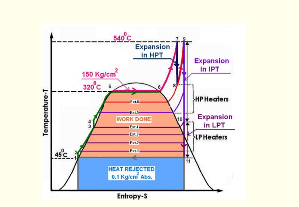
10
Rankine cycle T 4 1 3-3’ – BFP raises pressure from p2 to p1
The Carnot Cycle is theoretically most efficient, but it is having practical difficulties. For steam power plant, practical thermal cycle was suggested by Rankine, called Ideal cycle or Rankine cycle. T 4 1 T1 3-3’ – BFP raises pressure from p2 to p1 3’-4 – Heating In feed heaters & economizer 4 -1 – Heating In boiler 1-2 – Work done in Turbine from p1 to p2 2-3 – Heat reduction in condenser p1 3’ 2 T2 3 p2 S

15
WATER WALL BOTTOM RING HEADER
SH STEAM OUTLET CRH IN HRH OUT DRUM FRONT ROOF REAR ROOF REHEATER REAR FINAL SUPERHEATER PLATEN SUPERHEATER REHEATER FRONT SCW SH REAR EXT SCW SH LTSH EXTENDED WW SCW SH FRONT Economiser DOWN COMERS WATER INLET WATER WALL FRONT WATER WALL REAR WATER WALL BOTTOM RING HEADER

16
BASIC DATA FOR DESIGN BOILER PARAMTERS FUEL DATA SITE DATA

18
FUEL ANALYSIS COAL

19
Fuels Handled Coal / Oil / Natural Gas in any combination Lignite
Blast Furnace Gas / Coke Oven Gas / Corex Gas Carbon Monoxide / Tail gas Asphalt Black Liquor Bagasse Rice Husk Washery Rejects Wheat / Rice straw

20
FURNACE HEAT LOADINGS EPRS LOADING PLAN AREA LOADING
VOLUMETRIC LOADING BURNER ZONE HEAT RELEASE RATE

21
BOILER AUXILIARIES MILL FANS ELECTROSTATIC PRECIPITATOR AIRHEATERS

22
BOWL MILLS UNDER ERECTION

23
Bowl Mill (General Arrangement)
")
24
Tube Mill Arrangement (Typical)
")
25
Axial Reaction Fan (Single Stage)
")
26
Axial Reaction Fan (Double Stage)
")
27
Axial Fan Impulse Type (AN)
")
28
Radial Fan (Double Suction)
")
29
AIRPREHEATERS

30
ELECTROSTATIC PRECIPITATOR

31
TG FLOOR - THERMAL POWER PLANT

32
TYPICAL STEAM & WATER CIRCUIT

33
TYPICAL SCHEME OF AIR & GAS DUCTS / CIRCUITS
COLD PA SYSTEM

34
Once Through Supercritical Steam Generators

35
NTPC/ BARH II STPP – 2 x 660 MW Coal Fuel 568 / 596 oC Temperature
255/54.65 kg/cm2 (g) Pressure 2120/ t/h. Steam Flow Zero Date U6/1700 & U6/1701 Contract No. Not in SG Package Dust Collector 2 Nos. SAF 42.5/26.6-1, Axial Reaction-TLT ID Fan 2 Nos. PAF 19/10.6 – 2, Axial Reaction-TLT PA Fan 2 Nos. FAF 25/11.2 – 1, Axial Reaction-TLT FD Fan PAH - 2 Nos VI 58 (70)MR,2NOS VI 70 (82)MR ALSTOM Supply Airheater 9 Nos. Bowl Mill, HP 1103 Mill Major Auxiliaries Parameters at SHO / RHO BARH II – 2 x 660 MW Project National Thermal Power Corporation Customer
 Pressure. 2120/ t/h. Steam Flow Zero Date. U6/1700 & U6/1701. Contract No. Not in SG Package. Dust Collector. 2 Nos. SAF 42.5/26.6-1, Axial Reaction-TLT. ID Fan. 2 Nos. PAF 19/10.6 – 2, Axial Reaction-TLT. PA Fan. 2 Nos. FAF 25/11.2 – 1, Axial Reaction-TLT. FD Fan. PAH - 2 Nos VI 58 (70)MR,2NOS 31.5 VI 70 (82)MR ALSTOM Supply. Airheater. 9 Nos. Bowl Mill, HP Mill. Major Auxiliaries. Parameters at SHO / RHO. BARH II – 2 x 660 MW. Project. National Thermal Power Corporation. Customer.")
36
Steam generation process

37
T S DIAGRAM OUTPUT INCREASE D Temperature ( 0 C ) Boiling Water B C
Dry Saturated Steam E 24’0c F A -273 Entropy KJ / Kg K Basic Rankine Cycle

38
The Concept The mass flow rate thru’ all heat transfer circuits from Eco. inlet to SH outlet is kept same except at low loads wherein recirculation is resorted to protect the water wall system

39
Circulation Systems Drum Type Once-through

40
Thank You

Similar presentations


 Power Plant Rankine cycle Power Plant>")


. 4. Unit transformer (3-phase). 5. Electric generator (3-phase). 6. Low pressure.>")


