Download presentation
Presentation is loading. Please wait.

1
CONTROLS OF SUPER CRITICAL BOILERS
Presentation By AJAY SHUKLA Sr.Faculty PMI, Electricity generation is very complex in nature , where load demand changes on minute to minite basis, it is not manufacturing industry where u have got enough time match your demand and supply .In no industry other than power where real time matching of supply and demands is done on second to second basis. If you fail to response you are gone, and frequency may collapse or increase leading to grid failure. To match the demand you need continuous control of your turbine and boiler. Turbine is customer and boiler supplier but both should work in tandem to create win win situation

2
Boiler Turbine Control
Let us see how any power plant controls the load or generate the MW. There are two components boiler and turbine, turbine has it own controls , since it consist of rotating mass of around 200 T rotor, many precaution is taken so that no point of time it should not go in unsafe zone. Now see the boiler utimate aim of boiler is to generate steam at required pressure and temp for turbine . Every thing is so dynamic in boiler that very complex boiler control is required. In the boiler we are burning the fuel , we need air and water so all the controls are required. Since we are burning fossil fuel so Boiler manufacture ensure that his boiler remains safe in all operating conditions follows certain standards while

3
Boiler Following Mode Now we have to meet the load demand so we can follow certain strategy there are different mode in which When ever gen load is increased , tur c/v will be open first , then pr will be dropped , so FW and fuel has to increased to meet MW demand, load followin capacity will be fast in this case

4
Turbine Following Mode
In this when ever load is increased load demand will given first to increse Fuel and FW , Then based on pressure change load will be changed , so load following will be slow

5
Coordinate Mode Control
When ever load is increased the command is given to increse fuel flow and FW flow both as well as load is increased same time to meet demand , load followin will be fast and throttle pr will not dropped , In SC we follow this mode for fast load pick up

6
Coordinate Mode Control
This is CMC our unit generally run on this mode , many logic are in buiit based on unit capability and aux availibality , frequescy correction are taken as feed forward signal , what will happen if some thing will happen to any aux it gets tripped .

7
Drum and OT Control Comparison
1) I hope control for drum type is known to you , How we control feed water in drum type ,Drum acts as buffer ,It can work as 03 lement and 01 element .It is one of most important loop of C&I , Operation always demands this loop to be on auto ,So feed water loop which control the drum level in Drum type boiler in OT feed water controls the feed water flow. 2)Firing is there any differnce no 3) Pressure generally constant pressure but in OT it is sliding pressure control only. 4)
 I hope control for drum type is known to you , How we control feed water in drum type ,Drum acts as buffer ,It can work as 03 lement and 01 element .It is one of most important loop of C&I , Operation always demands this loop to be on auto ,So feed water loop which control the drum level in Drum type boiler in OT feed water controls the feed water flow. 2)Firing is there any differnce no. 3) Pressure generally constant pressure but in OT it is sliding pressure control only. 4)")
8
Drum and OT Control Comparison
Why super heater temp control required , how it is done in drum type there are 02 methods Burner Tilt and other is super heater spray In OT super heater spray is used for short duration and feed water and firing ratio is used fro long term temp control RH temp control is same for both Start up system Drum type circulation natural or forced and out let goes to condenser At low load Feed water flow is less so circulation

9
OT Control Overview Hear realese and heat demand has to be balanced

10
Cycle of Supercritical Power Plant
This is cycle of SC , extra is start up system

11
This is graphics based on PID and final garphic Fuel form 10 mills so 10 coal elevation, what mill u r giving all ball mill or tube , 2 LP , 2 COND CEP AND 4 LP 1-4 , 6-8 HPH where is 5th , b

12
Supercritical Power Plant
This is korean plant with 4 sepeartor

13
OT Control Overview We use start up syste, , scheme , FW / Firing rate either these feed forward we can use feed water side or fule side

14
OT Start up Control mode
30% of TMCR KEPT , IN SOME FW = X1 + X1 X2

15
Super Critical Units Controls Mode

16
Flushing Mode

17
Flushing Mode

18
Start-Up System with Recirculation
Recirculation Pump in Main Bypass Line SH Separator Flash Tank WW C ECO HWL To Condenser C Let see what is there in start up system , during start up water comes up to separator and it level is maintained, how that is maintained we will see Deaerator HPH C BFP

19
Start UP System Once sp level is maintained by WR and ZR valve , UG bcp

20
The separator water level remains stable for two(2) minutes
START-UP If the water system of the boiler is empty (economizer, furnace walls, separators), then the system is filled with approximately 10% TMCR feed water flow. When the level in the separator reaches set-point, the WR valve will begin to open. When the WR valve reaches >30% open for approximately one minute, then increase feed water flow set-point to 30% TMCR. As the flow increases, WR valve will reach full open and ZR valve will begin to open. The water system is considered full when: The separator water level remains stable for two(2) minutes and The WR valve is fully opened and ZR valve is >15% open for two(2) minutes.
, then the system is filled with approximately 10% TMCR feed water flow. When the level in the separator reaches set-point, the WR valve will begin to open. When the WR valve reaches >30% open for approximately one minute, then increase feed water flow set-point to 30% TMCR. As the flow increases, WR valve will reach full open and ZR valve will begin to open. The water system is considered full when: The separator water level remains stable for two(2) minutes. and. The WR valve is fully opened and ZR valve is >15% open for two(2) minutes.")
22
SEPARATOR STORAGE TANK LEVEL CONTROL
Separator level is maintained by the combined action of a separator storage tank level feed water demand and the positioning of WR and ZR drain valves. Feed water demand is developed in response to separator storage tank level error and total fuel flow so as to prevent tank level from dropping too low. The WR and ZR valves are controlled in a split range manner to maintain the liquid level once the level reaches a high limit. The WR valve will respond first and then the ZR when the WR exceeds its linear operating range. Tank geometry is such that fluctuations in tank level are very dynamic, for this reason, only proportional control action established through the WR/ZR function curves is used to position these valves in response to level error. Sp level maintained ,FW Demand is trimmed by Sp lvl

23
UG VALVE CONTROL Control objective:
Maintain minimum economizer inlet flow. Control action: The boiler circulating pump is started following the start of a turbine-driven feed water pump and the final clean-up cycle. This pump circulates feed water from the evaporator outlet back to the economizer inlet. Located at the outlet of this pump is the UG valve which controls economizer inlet flow during the start-up phase of operation. Demand for this recirculation control valve is established based on measured economizer inlet flow compared to a minimum boiler flow set point.

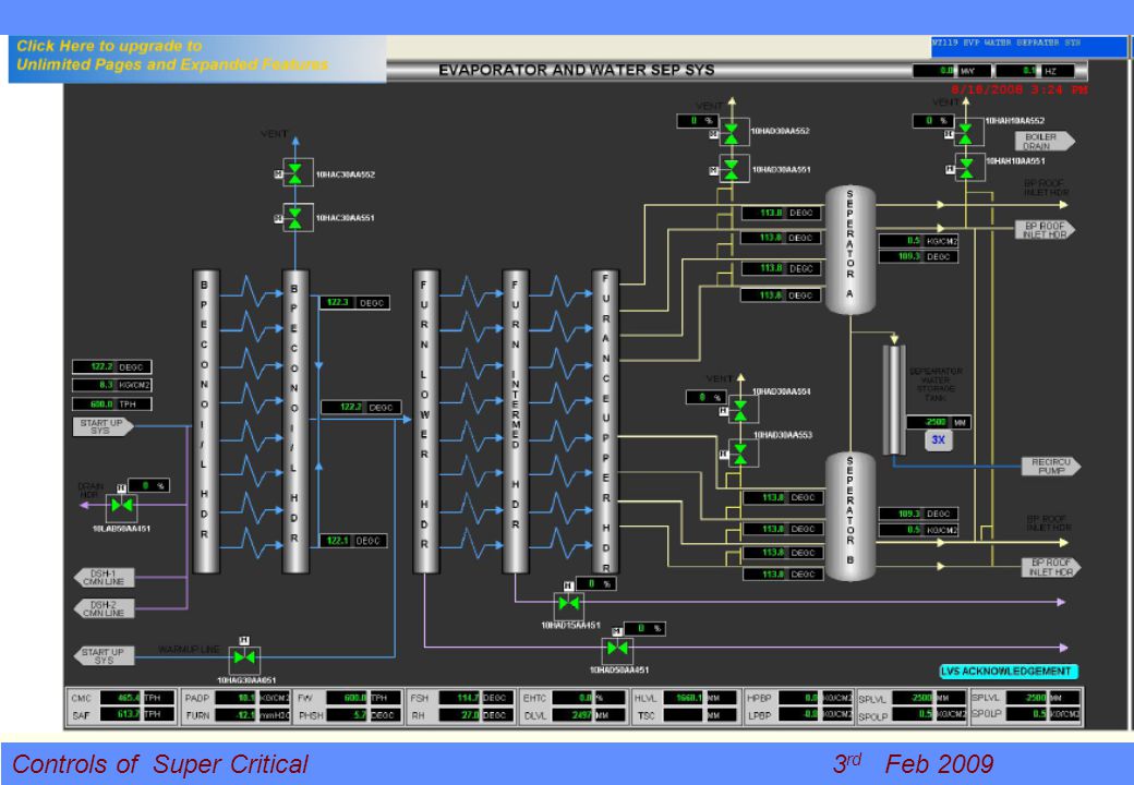
24
Separator water circuit of Super Critical
BCP required at load < 30 ie that is wet mode , this is genarl ckt name of valve is different

25
FEEDWATER CONTROL LOOP
Control objective: Develop total unit feed water demand as required to support unit load. Adjust feed water demand to maintain desired separator outlet temperature. Adjust separator outlet temperature set point as required to maintain acceptable platen superheat spray control range. Incorporate separator storage tank level (wet mode) feed water demand. Maintain minimum required economizer inlet flow. . Most important control loop CR 1 no storage luxury , why FW as per demand CR 1 , these are role
 feed water demand. Maintain minimum required economizer inlet flow. . Most important control loop CR 1 no storage luxury , why FW as per demand CR 1 , these are role.")
26
Feedwater Control This shows copmarison how feed water is controlled in drum type and once through , so in once through FW is not

27
Feed water firing rate ratio control

28
Feed water firing rate ratio control

29
Feed Forward with model
Process Setpoint Feed Forward f(x) MODEL S P +/- C -/+ D d dt K C +/- P +/- X
 MODEL. S. P. +/- C. -/+ D. d. dt. K. C. +/- P. +/- X.")
30
Feed Forward f(x) f(x) D D S X K K PROCESS FF process setpoint FF P
+/- C -/+ P +/- C -/+ D D d dt d dt K K C +/- P +/- C +/- P +/- S X

31
Model predictive control
+ MW _ Fuel with model Without model Turbine setpoint Water wall Temperature C 60 120 180 240 300 t[sec]

32
Firing Rate Master

33
Fuel Rate Master

34
Feed Forward Firing Rate Control

35
Feed Forward Firing Rate Control

36
ANY QUESTIONS PLEASE

37
Yuhuan 4x1000MW Preparation of light off

38
Multi-combusting Nozzles with Separated Overfire Air Damper

44
BCP (Boiler Circulating Pump) will be stopped automatically.
START-UP contd.. Water flows through the economizer and evaporator, and discharges the boiler through the WR valve to the flash tank and via connecting pipe to the condenser. Start BCP and open the UG valve to establish minimum water wall flow at 30% TMCR. As the pressure is raised, first the WR and then the ZR valves will open when separator water level increases due to boiler water swell. As pressure further increases, the WR and ZR valves will start to close as the water level decreases. The steam temperature at the separator inlet will reach a stable superheated condition at app. 30% TMCR, causing the level in the separator to decrease and eventually disappear. The boiler is now in once-through mode (dry mode). The BCP (Boiler Circulating Pump) will be stopped automatically. It is extremely important that minimum water wall flow be maintained at all times when firing the boiler to prevent tube damage due to overheating.
. The. BCP (Boiler Circulating Pump) will be stopped automatically. It is extremely important that minimum water wall flow be maintained at all times when firing the boiler to prevent tube damage due to overheating.")
45
FEEDWATER CONTROL LOOP contd..
Demand for feed water is established predominately by the Boiler Master demand. This signal, processed though a “boiler transfer function” provides the feed forward component of the total feed water demand. The “boiler transfer function” is a tunable dynamic element providing a means to dynamically match the feed water feed forward demand to actual evaporator heat transfer. Optimization of the feed forward in this manner minimizes temperature fluctuations that may otherwise result from varying dynamic response between the firing and feed water control systems (as they relate to evaporator heat transfer) thereby lessening the dependence on feedback correction.
 thereby lessening the dependence on feedback correction.")
46
FEEDWATER CONTROL LOOP contd..
The first controller acts on a load dependent average platen spray differential temperature. Its output represents the required adjustment to evaporator heat transfer/steam generation to maintain both the steam conditions and flue gas temperatures entering the platen superheat section so as to ensure adequate platen spray control range. A second controller acts on a load dependent separator outlet temperature set point corrected by the platen spray differential temperature controllers output. This controller acts to adjust feed water in response to firing system disturbances and the relatively fast effect they have on separator outlet steam temperatures. The overall combined feed water feedback control action is such that feed water demand is responsive to changes in the overall unit heat transfer profile.

47
FEEDWATER CONTROL LOOP contd..
The combined feed forward/feedback demand signal is subject to a minimum economizer inlet flow set point (wet mode) activated if the boiler circulation pump is not in service and the unit is being fired. This ensures the minimum economizer inlet cooling flow is maintained by the feed water supply system in the event the start-up system is not available. The feed forward/feedback demand signal is subject to a second “wet mode” feed water demand developed to support separator storage tank level control. The resulting demand provides the set point to a feed water master controller. The fuel/feed water ratio protection logic provides overriding control of individual feeder speed demands in the event of an excessively high fuel to feed water ratio.
 activated if the boiler circulation pump is not in service and the unit is being fired. This ensures the minimum economizer inlet cooling flow is maintained by the feed water supply system in the event the start-up system is not available. The feed forward/feedback demand signal is subject to a second wet mode feed water demand developed to support separator storage tank level control. The resulting demand provides the set point to a feed water master controller. The fuel/feed water ratio protection logic provides overriding control of individual feeder speed demands in the event of an excessively high fuel to feed water ratio.")
48
THANK YOU

Similar presentations


![An Introduction To Marine Steam Propulsion Plant [Source: US Navy]](/2/754532/big_thumb.jpg "An Introduction To Marine Steam Propulsion Plant [Source: US Navy]>")


