Download presentation
Presentation is loading. Please wait.

1
VRV III Product Selection Piping selection

2
Selection Considerations
Cooling Load calculations Heating Load calculations Internal and Ambient temp Building layout drawings Orientation Room Usage Fresh Air Requirements Air and temperature distribution Noise Levels Pipe Runs Unit Dimensions Aesthetics Planning Restrictions Possible future site expansion Total or sensible capacity selection ?

3
Outdoor and Indoor Unit selection is based on using the capacity index
Indoor unit size Capacity index 20 25 32 31.25 40 50 63 62.5 80 100 125 140 200 250 To select indoor unit and unit combinations, to size pipe work and refnet joints, we use ‘Index’ numbers: For example the index no of FXZQ20M7V1B is 20

4
Maximum Number of Indoor Units Connected to One Outdoor Unit
Outdoor untis Indoor units I.U combination index Cooling only Heat pump Heat recovery Maximal connectable Mininum Maximum VRV III VRV II For VRVIII For VRVII - RXYSQ4P7V3B 6 50 130 RXQ5P7W1B RXYSQ5P7V3B 8 62,5 162,5 RXYSQ6P7V3B 9 70 182 RXQ8P7W1B RXYQ8P7W1(B) REYQ8M7W1B 22 13 100 260 RXQ10P7W1B RXYQ10P7W1(B) REYQ10M7W1B 25 16 125 325 RXQ12P7W1B RXYQ12P7W1(B) REYQ12M7W1B 30 19 150 390 RXQ14P7W1B RXYQ14P7W1(B) REYQ14M7W1B 36 20 175 455 RXQ16P7W1B RXYQ16P7W1(B) REYQ16M7W1B 40 200 520 RXQ18P7W1B RXYQ18P7W1(B) REYQ18M7W1B 44 225 585 RXYQ20P7W1(B) REYQ20M7W1B 42 250 650 RXYQ22P7W1(B) REYQ22M7W1B 47 275 715 RXYQ24P7W1(B) REYQ24M7W1B 51 300 780 RXYQ26P7W1(B) REYQ26M7W1B 53 32 845 RXYQ28P7W1(B) REYQ28M7W1B 56 350 910 RXYQ30P7W1(B) REYQ30M7W1B 60 375 975 RXYQ32P7W1(B) REYQ32M7W1B 64 400 1040 RXYQ34P7W1(B) REYQ34M7W1B 425 1105 RXYQ36P7W1(B) REYQ36M7W1B 34 450 1170 RXYQ38P7W1B REYQ38M7W1B 475 1235 RXYQ40P7W1B REYQ40M7W1B 38 500 1300 RXYQ42P7W1B REYQ42M7W1B 525 1365 RXYQ44P7W1B REYQ44M7W1B 550 1430 RXYQ46P7W1B REYQ46M7W1B 575 1495 RXYQ48P7W1B REYQ48M7W1B 600 1560 RXYQ50P7W1B 625 1625 RXYQ52P7W1B 1690 RXYQ54P7W1B 675 1755
 REYQ8M7W1B RXQ10P7W1B. RXYQ10P7W1(B) REYQ10M7W1B RXQ12P7W1B. RXYQ12P7W1(B) REYQ12M7W1B RXQ14P7W1B. RXYQ14P7W1(B) REYQ14M7W1B RXQ16P7W1B. RXYQ16P7W1(B) REYQ16M7W1B RXQ18P7W1B. RXYQ18P7W1(B) REYQ18M7W1B RXYQ20P7W1(B) REYQ20M7W1B RXYQ22P7W1(B) REYQ22M7W1B RXYQ24P7W1(B) REYQ24M7W1B RXYQ26P7W1(B) REYQ26M7W1B RXYQ28P7W1(B) REYQ28M7W1B RXYQ30P7W1(B) REYQ30M7W1B RXYQ32P7W1(B) REYQ32M7W1B RXYQ34P7W1(B) REYQ34M7W1B RXYQ36P7W1(B) REYQ36M7W1B RXYQ38P7W1B. REYQ38M7W1B RXYQ40P7W1B. REYQ40M7W1B RXYQ42P7W1B. REYQ42M7W1B RXYQ44P7W1B. REYQ44M7W1B RXYQ46P7W1B. REYQ46M7W1B RXYQ48P7W1B. REYQ48M7W1B RXYQ50P7W1B RXYQ52P7W1B RXYQ54P7W1B")
5
Size 50 is the smallest to be connected
Maximum Number of Indoor Units Connected to BS Boxes (required for Heat Recovery Systems) Branch selector box Total index No of indoor units connectable System type No of BS boxes connectable R410a REYQ8M 13 REYQ10M 16 BSVQ100MVE Min – Max 8 REYQ12 – 20M 20 REYQ22M 22 BSVQ160MVE REYQ24 – 32M 32 REYQ34M 34 BSVQ250MVE 160 – 250 5 Size 50 is the smallest to be connected REYQ35M 36 REYQ38M 38 REYQ40 – 48M 40
 Branch selector box. Total index. No of indoor units connectable. System type. No of BS boxes connectable. R410a. REYQ8M. 13. REYQ10M. 16. BSVQ100MVE. Min – Max REYQ12 – 20M. 20. REYQ22M. 22. BSVQ160MVE REYQ24 – 32M. 32. REYQ34M. 34. BSVQ250MVE. 160 – Size 50 is the smallest to be connected. REYQ35M. 36. REYQ38M. 38. REYQ40 – 48M. 40.")
6
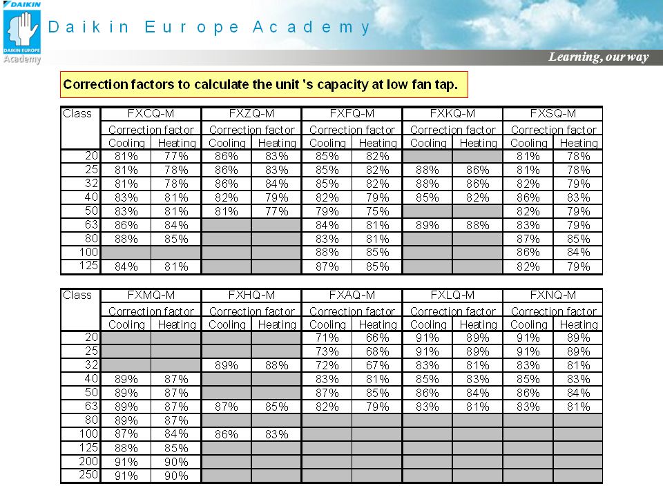
Indoor unit Selection FXCQ Based on High Fan Speed
For “Low Fan” Speed, capacity reduction is not published, but the correction factors from next slide may be used.

8
Select indoor units for room layout provided
Indoor Unit Selection Select indoor units for room layout provided “Example (FXCQ) of where information can be found” Starting from Engineering data book EEDE06-2 page 795: Noise Levels details Engineering data book EEDE06-2 page 815 Unit Dimensions Engineering data book EEDE06-2 page 798 Air Distribution Engineering data book EEDE06-2 page 818 Make a record of Model, Fan speed, Total and Sensible Cooling duties
 of where information can be found Starting from Engineering data book EEDE06-2 page 795: Noise Levels details Engineering data book EEDE06-2 page 815. Unit Dimensions Engineering data book EEDE06-2 page 798. Air Distribution Engineering data book EEDE06-2 page 818. Make a record of Model, Fan speed, Total and Sensible Cooling duties.")
9
Indoor Unit Selection 18 m Room A 8.0kw Sensible Cooling N 6 m 3 m 3 m
Room E 1.65 kw Sensible Room D 2.5 kw Sensible Room C 2.1 kw Sensible Room B 4.2 kw Sensible 3 m 6 m Room A - General Office Room B - Meeting Room Room C - Manager Room D - Small office Room E - Reception 3 m 6 m Rooms A, B and E 400mm ceiling void Room C 200 mm ceiling void Room D no void (restricted floor space) Ceiling Height 2.7m Internal design 23 deg C db 16 deg C wb Ambient design 29 deg C db
 Ceiling Height 2.7m. Internal design 23 deg C db. 16 deg C wb. Ambient design 29 deg C db.")
10
Indoor Unit Selection Possible Solution Note:
Internal design 23 deg C db 16 deg C wb Ambient design 29 deg C db Required Sensible Total Sensible Room A 3 x FXFQ40M 8.0 kW High Speed 10.8 kW 9.0 kW Room B 1 x FXSQ80M 4.2 kW Low Speed 5.97 kW 4.73 kW Room C 1 x FXLQ40M 2.1 kW 3.06 kW 2.3 kW Room D 1 x FXAQ40M 2.5 kW 3.60 kW 3.31 kW Room E 1 x FXSQ32M 1.65 kW 2.31 kW 1.88 kW Note: The low speed duties were calculated based on the correction factors shown in the previous table.

11
Condensing Unit Selection Considerations
Remember the maximum index connectable Remember the maximum number of indoor units Cooling Only, Heat Pump or Heat Recovery Positioning Noise levels Service Access space required

12
Condensing Unit Selection
18 m Room A 6 m FXFQ40M FXFQ40M FXFQ40M Room E Room D Room C Room B 3 m FXAQ40M FXSQ32M 6 m FXLQ40M FXSQ80M Condensing Unit Base 3 m 6 m

13
Indoor Unit Combination Index
Condensing Unit Selection Example: using Inverter 2 pipe Heat Pump Room A 3 x FXFQ40M Room B 1 x FXSQ80M 80 Room C 1 x FXLQ40M 40 Room D 1 x FXAQ40M 40 Room E 1 x FXSQ32M 31.25 Total Index Suitable Condensing Unit RXYQ10P7W1 Outdoor Unit Indoor Unit Combination Index Minimum Maximum RXYQ5P7W1 RXYQ8P7W1/REYQ8M RXYQ10P7W1/REYQ10M 62.5 100 125 162.5 260 325

14
Condensing Unit Selection
Example: using Inverter 2 pipe heat pump Room A 3 x FXFQ40M Room B 1 x FXSQ80M 80 Room C 1 x FXLQ40M 40 Room D 1 x FXAQ40M 40 Room E 1 x FXSQ32M 31.25 Total Index Suitable Condensing Unit RXYQ10P7W1 Look up condensing unit duty from EEDE06–2 page 196 At indoor temperature of 16 deg C wb and outdoor temp 29 deg C db Total Cooling with index of 308 = 24,8 kW Total Cooling at index of 336 = 27.0 kW Index connected = 336 – = 24.75 27,0 kW – 24,8 = 2.2 kW 336 – 308 = 28 2.2 kW/28 = kW 24.75 x = kW 27.0 kW – kW = kW

15
Condensing Unit Selection
Example: using Inverter 2 pipe heat pump (Back to the original data selected at high speed) Corrected Index Total Sensible Room A = 3 x FXFQ40M (high speed) 120 10.80kW 9.0kW 9,66kW 8,04kW Room B = 1 x FXSQ80M (low speed) 80 5.97 kW 4.73 kW 5,60 kW 4.44kW Room C = 1 x FXLQ40M 40 3.06 kW 2.3kW 2.73 kW 2.05kW Room D = 1 x FXAQ40M 3.6kW 3.3Kw 3.22Kw 2.96Kw Room E = 1 x FXSQ32M 31.25 2.37kW 1.88kW 2.08kW 1.69 kW Total index 311.25 Calculate corrected indoor unit capacity RXYQ10M total cooling = 25.05kW FXFQ40M = (40 x 25.05) = 3.22 kW total Reduce sensible by the same proportion prior to correction calculation Don’t forget to apply correction for low speed when necessary: FXSQ80 = (80 x 25.05) x 0.87 = 5,60 kW total 311.25 FXSQ80 = 4.73 x 5,60 = 4.44 kW sensible 5.97
 Corrected. Index. Total. Sensible. Room A. = 3 x FXFQ40M. (high speed) kW. 9.0kW. 9,66kW. 8,04kW. Room B. = 1 x FXSQ80M. (low speed) kW kW. 5,60 kW. 4.44kW. Room C. = 1 x FXLQ40M kW. 2.3kW kW. 2.05kW. Room D. = 1 x FXAQ40M. 3.6kW. 3.3Kw. 3.22Kw. 2.96Kw. Room E. = 1 x FXSQ32M kW. 1.88kW. 2.08kW kW. Total index Calculate corrected indoor unit capacity. RXYQ10M total cooling = 25.05kW. FXFQ40M = (40 x 25.05) = 3.22 kW total Reduce sensible by the same proportion prior to correction calculation. Don’t forget to apply correction for low speed when necessary: FXSQ80 = (80 x 25.05) x 0.87 = 5,60 kW total FXSQ80 = 4.73 x 5,60 = 4.44 kW sensible")
16
Condensing Unit Selection
Example: using Inverter 2 pipe heat pump Required Sensible Corrected Total Room A = 3 x FXFQ40M 8.0 kW High Speed 9,66kW 8,04kW Room B = 1 x FXSQ63M 4.2 kW Low Speed 5,60 kW 4.44kW Room C = 1 x FXLQ40M 2.1 kW 2.73 kW 2.05kW Room D = 1 x FXAQ40M 2.5 kW 3.22Kw 2.96Kw Room E = 1 x FXSQ25M 1.65 kW 2.08kW 1.69 kW Not yet ? Are we finished ?

17
Pipe Length Correction
Example: using Inverter 2 pipe heat pump Look up capacity correction ratio on page 294 of EEDE06-2 Table RXYQ10P For Room B FXSQ80M Run = 20m Level difference = Outdoor unit 3m below indoor unit Capacity reduction factor = 0.98

18
Pipe Length Correction
18 m Room A 6 m FXFQ40M FXFQ40M FXFQ40M Room E Room D Room C Room B 3 m FXAQ40M FXSQ32M 6 m FXLQ40M FXSQ80M Condensing Unit Base 3 m 6 m

19
Pipe Length Correction
(Change in Cooling Capacity) (H=m) 0.90 0.87 0.85 Outdoor situated above Indoor units 50 0.92 40 30 0.95 0.98 20 1.0 10 10 20 30 40 50 60 70 80 90 100 110 ……..190 m Example: Outdoor unit 3m below Indoor unit 10 1.0 20 0.98 30 Outdoor situated below Indoor units 40 0.95 0.92 0.90 0.87 0.85 (H=m)
 (H=m) Outdoor situated. above. Indoor units ……..190 m. Example: Outdoor unit. 3m below. Indoor unit Outdoor situated. below. Indoor units (H=m)")
20
Pipe Length Correction
Example: using Inverter 2 pipe heat pump Corrected Pipe length Correction factor required Pipe length corrected Total Sensible Room A = 1 x FXFQ40M 9,66kW 8,04kW 15M 11M 7M 0.99 3,18kW 2.66kW Room B = 1 x FXSQ80M 5,60 kW 4.44kW 20M 0.98 5,49kW 4.35kW Room C = 1 x FXLQ40M 2.73 kW 2.05kW 16M 2,68kW 2.02kW Room D = 1 x FXAQ40M 3.22Kw 2.96Kw 10M 3.18kW 2,93kW Room E = 1x FXSQ32M 2.08kW 1.69 kW 4M 1.00 2.06kW 1.67kW

21
Additional correction due to Defrost operation
Defrost operation protects the outdoor unit coil against freezing: Happens in heating mode Performs once max every 2 hours Duration: between 4 and 8 min During defrost: outdoor/indoor units’ fans are stopped No heating is delivered during defrost Limited cooling is delivered (heat recovery models) Capacity tables do not take account of this capacity reduction The heating capacity should be ammended by a correction factor:
 Capacity tables do not take account of this capacity reduction. The heating capacity should be ammended by a correction factor:")
22
Summary of selection after corrections
Example: using Inverter 2 pipe heat pump Required sensible Result total Result sensible Room A = 3 x FXFQ40M 8.0 kW High Speed 10,66kW 8,04kW Room B = 1 x FXSQ80M 4.2 kW Low Speed 5,49kW 4.35kW Room C = 1 x FXLQ40M 2.1 kW 2,68kW 2.02kW Room D = 1 x FXAQ40M 2.5 kW 3.18kW 2,93kW Room E = 1 x FXSQ32M 1.65 kW 2.06kW 1.67kW If selected fan coil unit corrected duty is too low, then that unit has to be re-selected and the complete procedure repeated

23
Would this suit Heat Recovery?
Room A FXFQ40M FXFQ40M FXFQ40M Room E Room D Room C Room B FXAQ40M FXSQ32M FXLQ40M FXSQ80M Meeting Room

24
VRVII Heat Recovery: selection of BS Boxes
Room A BSVQ160MVE Min – Max FXFQ40M FXFQ40M FXFQ40M Room E Room D Room C Room B FXAQ40M FXSQ32M Condensing Unit Base with REYQ10M FXLQ40M FXSQ80M BS Box BSVQ100MVE Min – Max

25
VRV III “P7” Series Selection by VRV Express

26
VRV Selection Software
VRV Express VRV Selection Software

27
VRV Express

28
VRV Express

29
VRV Express

30
VRV Express

31
VRV Express

32
VRV Express Material list Model Qty Description REYQ12M 1
Heat recovery VRV M R410A REYQ8M BSVQ100M 4 Branch selector unit R410A BSVQ160M 3 FXAQ40M A - Wall mounted unit FXFQ50M 2 F - 4-way blow ceiling mounted cassette FXFQ80M FXSQ40M S - Concealed ceiling mounted FXSQ80M KHRQ22M20T7 REFNET branch piping kit KHRQ23M29T7 KHRQ23M64T7 DCS601A51 I controller BRC1D517 8 Wired remote control BYC125KJW1 Decoration panel

33
VRV Express Indoor unit details Name Model Tmp C Rq TC Av TC Rq SC
Av SC Tmp H Rq HC Av HC Airflow Sound MCA WxHxD Wght °C kW l/s dBA A mm kg First Floor - Room 101 FXFQ50M 22.0 4.0 4.9 3.5 3.8 21.0 2.0 4.5 27-32 0.3 840x246x840 24 First Floor - Room 102 First Floor - Room 103 FXFQ80M 5.5 7.8 3.2 7.1 31-36 0.5 25 First Floor - Room 104 First Floor - Room 105 FXSQ80M 6.2 37-43 1.4 1400x300x800 51 First Floor - Room 106 FXSQ40M 3.0 3.9 2.5 2.9 32-38 0.6 700x300x800 30 Second Floor - Room 201 3.7 2.8 3.6 Second Floor - Room 203 6.0 7.5 5.2 7.2 Second Floor -Room 204 Second Floor - Room 205 FXAQ40M 1.8 34-39 0.4 1050x290x230 14

34
VRV III “P” Series Field Pipe work - Application

35
NEVER install a joint after a header !
VRV refrigerant piping system is based on REFNETS Advantages of REFNET system: Short dimensioning time Short installation time REFNET joint REFNET header The VRV system has realized the REFNET piping system to facilitate simple piping construction through original refrigerant control. As a result, not only piping design is drastically simplified but also piping extending in a building is drastically curtained. Dedicated joints and headers are prepared for branch portions where construction is said difficult. Both design and construction are simplified to realize easiness of level same as that of water piping in a central air conditioning system. Further, sue of the DAIKIN piping/wiring distribution diagram preparation software will enable simple check of piping diagrams. NEVER install a joint after a header ! ● ● ● ● ●

36
+ 30° Joints are to be mounted …. Refnet installation recommendations
Vertically …..Horizontally + 30°

37
Select refnets according to the capacity according to the capacity
REFNET piping system Select refnets according to the capacity Adjust the pipe size according to the capacity prototypes Possibly match pipe and refnet using adaptors

38
Refrigerant Pipe Work Maximum “Actual” Piping Limitations
Can become 90 m in certain conditions A For level differences above 50m; One size up of main liquid pipe Option kit 40M 15M 90M 165M Total piping length = 1000M No Oil traps No Liquid traps No Solenoid valves No Sight glasses No Driers No Additional oil Max pressure test 38.5 bar 190M Max EQUIVALENT LENGTH

39
Field Piping Limitations VRV III P series (Heat pump Inverter)
“Longest” – “shortest” branch = b+c+d+e+l-f <=40m f, g,h, j, k, l, m, n <= 40m Pipes b, c, d, e between first and last kit are sized up For the total piping calculation the actual length of b, c, d, e is counted double if 90m RXYQ…P Can be 40m 165m a b c d e 90m NEVER INSTALL A JOINT AFTER A HEADER j k f h g l n FXHQ….M FXCQ….M FXCQ….M FXSQ….M FXAQ….M m 15m FXLQ….M FXLQ….M FXLQ….M

40
VRVII “M” Series Field Piping Limitations (Heat Recovery)
REYQ….M 150m 40M 50m BSVQ. .M BSVQ. .M BSVQ. .M BSVQ. .M BSVQ. .M BSVQ. .M BSVQ. .M FXHQ….M FXCQ….M FXCQ….M FXSQ….M BSVQ. .M BSVQ. .M 15m FXLQ….M FXLQ….M FXLQ….M FXLQ….M FXLQ….M

41
Piping joints required at the first branch
Refnet joints for 2 pipe Outdoor system type KHRQ22M20T RX(Y)Q5 KHRQ22M29T9 RX(Y)Q8~10 KHRQ22M64T RX(Y)Q12~18 + RXYQ20~22 KHRQ22M75T RXYQ24~54 Refnet joints for 3 pipe KHRQ23M29T7 REQY8 – 10 KHRQ23M64T7 REYQ12 – 22 KHRQ23M75T7 REYQ24> VRV III VRV II H/R
Q5. KHRQ22M29T9. RX(Y)Q8~10. KHRQ22M64T. RX(Y)Q12~18 + RXYQ20~22. KHRQ22M75T. RXYQ24~54. Refnet joints for 3 pipe. KHRQ23M29T7. REQY8 – 10. KHRQ23M64T7. REYQ12 – 22. KHRQ23M75T7. REYQ24> VRV III. VRV II H/R.")
42
Piping Joints other than the first branch
Refnet joints for 2 pipe Connectable index KHRQ22M20T <200 KHRQ22M29T9 200 - <290 KHRQ22M64T 290 - <640 KHRQ22M75T >640 Refnet joints for 3 pipe KHRQ23M20T7 KHRQ23M29T7 KHRQ23M64T7 KHRQ23M75T7 640> VRV III VRV II H/R

43
Do NOT increase the size !
Selection of Piping Joints 1st joint corresponds to outdoor unit 2nd Joint according to class total Possibly, this results into a bigger joint than the 1st joint ! Do NOT increase the size !

44
Piping Headers PLEASE NOTE : Class 250 CANNOT be connected to a header
Refnet header for 2 pipe Connectable index KHRQ22M29H <290 KHRQ22M64H 290 - <640 KHRQ22M75H 640> Refnet header for 3 pipe KHRQ23M29H7 <200 200 - <290 KHRQ23M64H7 KHRQ23M75H7 PLEASE NOTE : Class 250 CANNOT be connected to a header

45
Pipe Size connections to the outdoor units Heat Pump model
Outdoor model Gas pipe Liquid pipe RX(Y)Q5 15.9mm 9.5mm RX(Y)Q8 19.1mm RX(Y)Q10 22.2mm RX(Y)Q12, 14, 16 28.6mm 12.7mm RX(Y)Q18 +RXYQ20-22 RXYQ24 34.9mm RXYQ26-34 RXYQ36-54 41.3mm
Q mm. 9.5mm. RX(Y)Q mm. RX(Y)Q mm. RX(Y)Q12, 14, mm. 12.7mm. RX(Y)Q18 +RXYQ RXYQ mm. RXYQ RXYQ mm.")
46
Pipe Sizing between refnet branch kits for heat pump models
Piping Total unit capacity Gas (outer diameter) Liquid <150 15.9mm 9.5mm 150-->200 19.1mm 200 - >290 22.2mm 290 - <420 28.6mm 12.7mm 420 - <640 640 - <920 34.9mm >920 41.3mm Adjust the pipe size according to the capacity Possibly, this results into a bigger pipe than the one coming from the outdoor unit ! Do NOT increase the size !
 Liquid. < mm. 9.5mm > mm > mm < mm. 12.7mm < < mm. > mm. Adjust the pipe size. according to the capacity. Possibly, this results into a bigger pipe than the one coming from the outdoor unit ! Do NOT increase the size !")
47
Refrigerant pipe Size Connections to Indoor Units
The pipe size of the indoor unit Total indoor unit capacity Gas Liquid 20, 25, 32, 40, 50 12.7mm 6.4mm 63, 80, 100, 125 15.9mm 9.5mm 200 19.1mm 250 22.2mm Please note: all the above connections are flared other than the gas pipe connection on the 200 an 250 models being brazed style

48
Pipe Size connections to the outdoor units for Heat recovery
Outdoor model Gas pipe Liquid pipe Discharge pipe REYQ8 19.1mm 9.5mm 15.9mm REYQ10 22.2mm REYQ12 28.6mm 12.7mm REYQ14, 16 Pipe Sizing between refnet branch kits for Heat recovery Total unit capacity Gas Discharge Liquid <63 12.7mm 9.5mm 6.4mm 63 - <200 15.9mm 200 - <290 22.2mm 19.1mm 290 - <420 28.6mm 420 - <640 640 - <920 34.9mm >920 41.3mm

49
Overall Equivalent length =
Equivalent length = a reference for a pressure drop of an component in the pipe work = length of linear pipes + allowances for fittings Branch selector box = 4m Refnet header = 1m Refnet joint = 0.5m 41.3mm 1 – 5/5 bend = 0.7m 34.9mm 1 – 3/8 bend = 0.66m 28.mm 1 – 1/8 bend 22.2mm 7/8 bend = 0.4m 19.1mm 3/4 bend = 0.25m 12.7mm 1/2 bend = 0.22m 9.5mm 3/8 bend = 0.18m The following allowances should be allocated to the following components: Overall Equivalent length = =(Equivalent length of main pipe work x 0.5) + Equivalent length of branch pipe work
 + Equivalent length of branch pipe work.")
50
Increase only liquid for
What happens when the overall equivalent length from the condensing unit to any indoor unit exceeds 90 m ? Increase diameter of the Liquid AND the Gas pipes between the condenser and the first refnet BUT ! ! Increase only gas for RX(Y)Q5P7 Increase only liquid for RXYQ12,14,24, 36~54 P REYQ : The WHOLE RANGE
Q5P7. Increase only liquid for. RXYQ12,14,24, 36~54 P. REYQ : The WHOLE RANGE.")
51
Equivalent length: example of calculation
E. Length 40m (80m x 0.5) Overall Equivalent length = = 80m 40m (No increase in pipe size required) Section to be increased in size Equivalent length 110m E. Length 40m (110m x 0.5) Overall Equivalent length = = 95m 40m (An increase in main pipe work size is required) Section to be increased in size
 Overall Equivalent length = + = 80m. 40m. (No increase in pipe size required) Section to be. increased in size. Equivalent length. 110m. E. Length. 40m. (110m x 0.5) Overall Equivalent length = + = 95m. 40m. (An increase in main pipe work size is required) Section to be. increased in size.")
52
Equivalent length > 90 m
Increase diameter in case of Heat Pump SYSTEM REFERENCE UP TO 90 METERS OVER 90 METERS GAS LIQUID GAS LIQUID RXYQ5P 15.9mm 9.5mm 19.1mm 9.5mm RXYQ8P 19.1mm 9.5mm 22.2mm 12.7mm RXYQ10P 22.2mm 9.5mm 22.2mm 12.7mm RXYQ12P 28.6mm 12.7mm 28.6mm 15.9mm RXYQ14P 28.6mm 12.7mm 28.6mm 15.9mm RXYQ16P 28.6mm 12.7mm 28.6mm 15.9mm RXYQ18P 28.6mm 15.9mm 28.6mm 19.1mm RXYQ20P 28.6mm 15.9mm 28.6mm 19.1mm RXYQ22P 28.6mm 15.9mm 28.6mm 19.1mm RXYQ24P 34.9mm 15.9mm 34.9mm 19.1mm RXYQ26P 34.9mm 19.1mm 34.9mm 22.2mm RXYQ28P 34.9mm 19.1mm 34.9mm 22.2mm RXYQ30P 34.9mm 19.1mm 34.9mm 22.2mm RXYQ32P 34.9mm 19.1mm 34.9mm 22.2mm RXYQ34P 34.9mm 19.1mm 34.9mm 22.2mm RXYQ36P 41.3mm 19.1mm 41.3mm 22.2mm 22.2mm RXYQ38P 41.3mm 19.1mm 41.3mm 22.2mm RXYQ40P 41.3mm 19.1mm 41.3mm 22.2mm RXYQ42P 41.3mm 19.1mm 41.3mm 22.2mm ……. 41.3mm 19.1mm 41.3mm 22.2mm RXYQ52P 41.3mm 19.1mm 41.3mm 22.2mm RXYQ54P 41.3mm 19.1mm 41.3mm 22.2mm

53
Equivalent length > 90 m
Increase diameter in case of Heat Recovery SYSTEM REFERENCE UP TO 90 METERS GAS DISCHARGE LIQUID 19.1mm 22.2mm 28.6mm 34.9mm 41.3mm 9.5mm 12.7mm 15.9mm REYQ8M REYQ10M REYQ12M REYQ14M REYQ16M REYQ18M REYQ20M REYQ22M REYQ24M REYQ26M REYQ28M REYQ30M REYQ32M REYQ34M REYQ36M REYQ38M REYQ40M REYQ42M REYQ44M REYQ46M REYQ48M OVER 90 METERS

54
Piping Between modules forming a Condensing unit Heat pump (P7 series)
To indoor units No oil equalization line required for P7 models = Liquid Line = Gas Line

55
Piping Between modules forming a Condensing unit Heat recovery (M series)
To indoor units = ¼” (6.4mm) Oil Equalising Line (only for REYQ18 or more) = Liquid Line = Gas Line = Discharge Line
 Oil Equalising Line (only for REYQ18 or more) = Liquid Line. = Gas Line. = Discharge Line.")
56
Pipe limitations between modules forming a Condensing unit
Branch Maximum pipe length 10m (13 m equiv.) or less A B C
 or less. A. B. C.")
57
Pipe Sizing Between Outdoor Units
Heat pump branch kit Two unit connection kit BHFQ22P1007 Three unit connection kit BHFQ22M1517 Heat recovery branch kit KHFQ23M907 BHFQ23M1357

58
Pipe Sizing Between Outdoor Units VRVIII
h m < ~ 54

59
Pipe Sizing Between Outdoor Units VRVII H/R
h m <

60
Additional Refrigerant Charge Calculation for VRVIII
takes in consideration the total lengths of liquid piping (m) TOTAL 22.2 = x 0.37 = + TOTAL 19.1 = x 0.26 = TOTAL 15.9 = x 0.18 = TOTAL = x 0.12 = TOTAL 9.5 = x = TOTAL = x = = R (additional kg R410) R should be rounded off in units of 0,1 kg
 TOTAL 22.2 = x 0.37 = + TOTAL 19.1 = x 0.26 = TOTAL 15.9 = x 0.18 = TOTAL 12.7 = x 0.12 = TOTAL 9.5 = x = TOTAL 6.4 = x = = R (additional kg R410) R should be rounded off in units of 0,1 kg.")
61
Additional Refrigerant Charge Calculation for VRVII H/R
takes in consideration the total lengths of liquid piping (m) TOTAL 22.2 = x 0.35 = + TOTAL 19.1 = x 0.25 = TOTAL 15.9 = x 0.17 = TOTAL = x 0.11 = TOTAL 9.5 = x = TOTAL = x = 0 kg (8-16 HP) 3 kg (18-32 HP) 6 kg (34-48 HP) R= x 1.15
 TOTAL 22.2 = x 0.35 = + TOTAL 19.1 = x 0.25 = TOTAL 15.9 = x 0.17 = TOTAL 12.7 = x 0.11 = TOTAL 9.5 = x = TOTAL 6.4 = x = 0 kg (8-16 HP) 3 kg (18-32 HP) 6 kg (34-48 HP) R= x")
62
ADDITIONAL REFRIGERANT CHARGE CALCULATION
Field Pipe sizing & Additional “Refrigerant” Charging Example of centralizing table BRANCH SELECTOR BOX SUCTION DISCHARGE LIQUID SUCTION LIQUID JOINT HEADER A A L 1 U B M 2 V C N 3 W D O 4 X R_____ M E P 5 Y F Q 6 Z G R ADDITIONAL REFRIGERANT CHARGE CALCULATION H S TOTAL = X = + TOTAL = X = TOTAL = X = I T A 15 5 B J K 10 10 6 6 6 Z C D E 6 L L U V G W H 4 X Y I 4 F K K 6 J 1 1 2 3 4 5 1 1 M N 1 O 1 P 6 Q 1 32 40 25 80 40 40 2 2 2 15m R S T T 40 40 40 No additional oil required!

63
EN378-2 (2000 Version) Piping material “The material, wall thickness,
R-410A material Minimum thickness Size t(mm) C1220- EN378-2 (2000 Version) ø 6,4 O 0,80 ø 9,5 O 0,80 “The material, wall thickness, tensile strength, ductility, corrosion resistance, forming and testing methods shall be suitable for the refrigerant used and withstand the pressure and stresses which may occur” ø12,7 O 0,8 ø15,9 O 0,99 ø19,1 1/2H 0,80 ø22,2 1/2H 0,80 ø28,6 1/2H 0,99 ø34,9 1/2H 1,21 ø41,3 1/2H 1,43 O : Annealed ½ H: Half Hard For half hard pipes the maximum allowed tensile stress is 61N/mm² for this reason, the 0.2% proof strength of the half hard pipe shall be minimum 61N/mm² The bending radius is more or equal to 3 times the diameter of the pipe The same requirements are valid for refnet headers and joints The maximum working pressure for R-410A VRV P-series is 38 bar
 C1220- EN378-2 (2000 Version) ø. 6,4. O. 0,80. ø. 9,5. O. 0,80. The material, wall thickness, tensile strength, ductility, corrosion resistance, forming. and testing methods shall be. suitable for the refrigerant. used and withstand the. pressure and stresses which. may occur ø12,7. O. 0,8. ø15,9. O. 0,99. ø19,1. 1/2H. 0,80. ø22,2. 1/2H. 0,80. ø28,6. 1/2H. 0,99. ø34,9. 1/2H. 1,21. ø41,3. 1/2H. 1,43. O : Annealed. ½ H: Half Hard. For half hard pipes the maximum allowed tensile stress is 61N/mm². for this reason, the 0.2% proof strength of the half hard pipe shall be. minimum 61N/mm². The bending radius is more or equal to 3 times the diameter of the pipe. The same requirements are valid. for refnet headers and joints. The maximum working pressure for R-410A VRV P-series is 38 bar.")
64
Piping Between Outdoor Units: possible patterns
Piping installation recommendations Piping Between Outdoor Units: possible patterns Unit A Unit B Unit C To indoor units To indoor units Unit A Unit B Unit C

65
Piping Between Outdoor Units: non recommended patterns
Piping installation recommendations Piping Between Outdoor Units: non recommended patterns Unit A To indoor units Unit B Unit C Unit A Unit B Unit C To indoor units When there is a downward inclination, the oil remains in the pipework

66
Piping installation recommendations
Piping Between Outdoor Units: non recommended patterns To indoor units Unit A Unit B Unit C To indoor units Unit A Unit B Unit C Oil collects in the outdoor unit that has stopped operating

67
Piping Between Outdoor Units: non recommended patterns
Piping installation recommendations Piping Between Outdoor Units: non recommended patterns Unit A Unit B Unit C To indoor units Unit A Unit B Unit C To indoor units Oil collects in unit C when the system stops

68
Piping Between Outdoor Units installed at different levels
Piping installation recommendations Piping Between Outdoor Units installed at different levels Unit A Unit B Max. height difference = 5m To indoor units Unit C Rising height: 200mm or more

69
Piping Between Outdoor Units in case of connections longer than 2m
Piping installation recommendations Piping Between Outdoor Units in case of connections longer than 2m Rising height: 200mm or more Unit A Unit B Unit C To indoor units 2m or less 2m or more Rising height: 200mm or more Rising height: 200mm or more Unit A Unit B Unit C To indoor units 2m or less 2m or less

Similar presentations


>")


