Download presentation
Presentation is loading. Please wait.

1
ERT 313 BIOSEPARATION ENGINEERING EXTRACTION
Prepared by: Miss Hairul Nazirah Abdul Halim

2
Definition of Extraction
Liquid-Liquid extraction is a mass transfer operation in which a liquid solution (the feed) is contacted with an immiscible or nearly immiscible liquid (solvent) that exhibits preferential affinity or selectivity towards one or more of the components in the feed. Purpose of Extraction To separate closed-boiling point mixture Mixture that cannot withstand high temperature of distillation Example: - recovery of penicillin from fermentation broth solvent: butyl acetate - recovery of acetic acid from dilute aqueous solutions solvent: ethyl-acetate
 is contacted with an immiscible or nearly immiscible liquid (solvent) that exhibits preferential affinity or selectivity towards one or more of the components in the feed. Purpose of Extraction. To separate closed-boiling point mixture. Mixture that cannot withstand high temperature of distillation. Example: - recovery of penicillin from fermentation broth. solvent: butyl acetate. - recovery of acetic acid from dilute aqueous solutions. solvent: ethyl-acetate.")
3
Extraction Equipment Batchwise or continuous operation
Feed liquid + solvent (put in agitated vessel) = layers (to be settled and separated) Extract – the layer of solvent + extracted solute Raffinate – the layer from which solute has been removed Extract may be lighter or heavier than raffinate. Continuous flow – more economical for more than one contact process
 = layers (to be settled and separated) Extract – the layer of solvent + extracted solute. Raffinate – the layer from which solute has been removed. Extract may be lighter or heavier than raffinate. Continuous flow – more economical for more than one contact process.")
4
Extraction Equipments:
- Mixer settlers - Packed extraction towers - Perforated plate towers - Baffle towers - Agitated tower extractors Auxiliary equipment: - stills, evaporators, heaters and condenser

7
Extraction of Dilute Solution
Extraction factor is defined as: Where: E = extraction factor KD = distribution coefficient V = volume of solvent L = volume of aqueous

8
For a single-stage extraction with pure solvent;
- the fraction of solute remaining is - the fraction recovered is

9
Extraction of Concentrated Solution
Equilibrium relationship are more complicated – 3 or more components present in each phase Equilibrium data are often presented on a triangular diagram such as Fig 23.7 and 23.8

11
Consider Fig 23.7 Line ACE shows extract phase Line BDE shows raffinate phase Point E is the plait point – the composition of extract & raffinate phases approach each other Tie line – a straight line joining the composition of extract & raffinate phases. Tie line in Fig 23.7 slope up to the left – extract phase is richer in acetone than the raffinate phase. This suggest that most of the acetone could be extract from water phase using moderate amount of solvent.

13
Consider Fig 23.8 Line AD shows extract phase Line BC shows raffinate phase Tie line in Fig 23.8 slope up to the right – extraction would still be possible But more solvent would have to use. The final extract would not be as rich in desired component (MCH)
")
14
How to obtain the phase composition using the triangular diagram?
- Point M: 0.2 Acetone, 0.3 water, 0.5 MIK - Draw a new tie line - Extract phase: acetone, water, MIK - Raffinate phase: acetone, water, MIK - Ratio of acetone to water in the product = 0.232/0.043 = 5.4 - Ratio of acetone to water in the raffinate = 0.132/0.845 =0.156 Let’s compare with Fig Which system is more effective?

15
Coordinates Scale Refer to Treybal, Mass Transfer Operation, 3rd ed., McGraw Hill The book use different triangular system The location of solvent (B) is on the right of the triangular diagram (McCabe use on the left) Coordinate scales of equilateral triangles can be plotted as y versus x as shown in Fig 10.9 Y axis = wt fraction of component C (acetic acid) X axis = wt fraction of solvent B (ethyl acetate)
 is on the right of the triangular diagram (McCabe use on the left) Coordinate scales of equilateral triangles can be plotted as y versus x as shown in Fig Y axis = wt fraction of component C (acetic acid) X axis = wt fraction of solvent B (ethyl acetate)")
17
Single-Stage Extraction

18
The triangular diagram in Fig 10
The triangular diagram in Fig (Treybal) is a bit different as compared to Fig (McCabe) Extract phase – on the left Raffinate phase - on the right Fig shows that we want to extract component C from A by using solvent B. Total material balance: Material balance on C:
 is a bit different as compared to Fig (McCabe) Extract phase – on the left. Raffinate phase - on the right. Fig shows that we want to extract component C from A by using solvent B. Total material balance: Material balance on C:")
19
Amount of solvent to provide a given location for M1 on the line FS:
The quantities of extract and raffinate: Minimum amount of solvent is found by locating M1 at D Maximum amount of solvent is found by locating M1 at K

20
Multistage Crosscurrent Extraction

21
Multistage Crosscurrent Extraction
Continuous or batch processes Refer to Fig 10.14 Raffinate from the previous stage will be the feed for the next stage The raffinate is contacted with fresh solvent The extract can be combined to provide the composited extract The total balance for any stage n: Material balance on C:

22
Tutorial 4 Batch Extraction EXAMPLE 23.2.
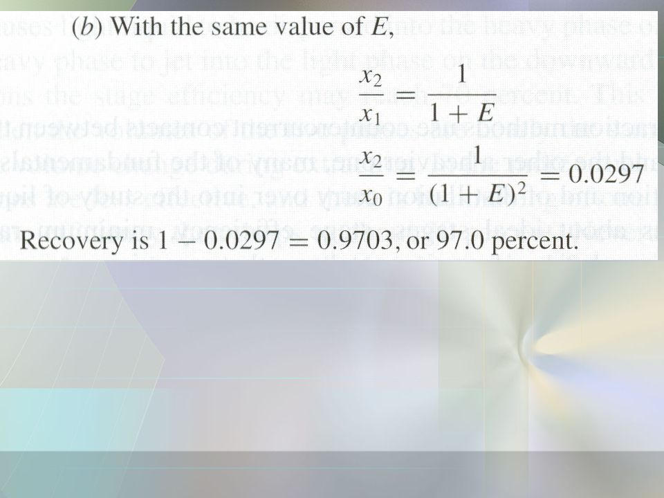
Penicillin F is recovered from a dilute aqueous fermentation broth by extraction with amyl acetate, using 6 volumes of solvent per 100 volumes of the aqueous phase. At pH 3.2 the distribution coefficient KD is 80. (a) What fraction of the penicillin would be recovered in a single ideal stage? (b) What would be the recovery with two-stage extraction using fresh solvent in both stages?
 What fraction of the penicillin would be recovered in a single ideal stage (b) What would be the recovery with two-stage extraction using fresh solvent in both stages")
25
Continuous Single Stage Extraction
An inlet water solution of 100 kg/h containing wt fraction nicotine in water is stripped with a kerosene stream of 200 kg/h containing wt fraction nicotine in a single stage extraction unit. It is desired to reduce the concentration of the exit water to wt fraction nicotine. Calculate the flow rate of the nicotine in both of the exit streams.

26
SOLUTION Nicotine in the feed solution = 100 (0.01) = 1 kg/h nicotine Water in feed = 100 ( ) = 99 kg/h water Nicotine in solvent = 200 (0.0005) = 0.1 kg/h nicotine Kerosene = 200 (1 – ) = kg/h kerosene Exit stream of aqueous phase, L1 Water = 99 kg/h = (1 – ) L1 L1 = kg/h (nicotine + water) Nicotine = – 99 = kg/h nicotine in exit stream 4. Exit stream of solvent phase, V1 Solvent = kg/h Nicotine in solvent = (1 – 0.099) = kg/h in exit stream Solvent + Nicotine = = kg/h
 = 0.1 kg/h nicotine. Kerosene = 200 (1 – ) = kg/h kerosene. Exit stream of aqueous phase, L1. Water = 99 kg/h = (1 – ) L1. L1 = kg/h (nicotine + water) Nicotine = – 99 = kg/h nicotine in exit stream. 4. Exit stream of solvent phase, V1. Solvent = kg/h. Nicotine in solvent = (1 – 0.099) = kg/h in exit stream. Solvent + Nicotine = = kg/h.")
27
Multistage Crosscurrent Extraction
If 100 kg of a solution of acetic acid (C) and water (A) containing 30% acid is to be extracted three times with isopropyl ether (B) at 20°C, using 40 kg of solvent in each stage, determine the quantities and compositions of the various streams. How much solvent would be required if the same final raffinate concentration were to be obtained with one stage? The equilibrium data at 20°C are listed below [Trans. AIChE, 36, 628 (1940), with permission].
 and water (A) containing 30% acid is to be extracted three times with isopropyl ether (B) at 20°C, using 40 kg of solvent in each stage, determine the quantities and compositions of the various streams. How much solvent would be required if the same final raffinate concentration were to be obtained with one stage The equilibrium data at 20°C are listed below [Trans. AIChE, 36, 628 (1940), with permission].")
29
SOLUTION The horizontal rows give the concentrations in equilibrium solutions. The system is of the type shown in Fig. 10.9, except that the tie lines slope downward toward the B apex. The rectangular coordinates of Fig. l0.9a will be used, but only for acid concentrations up to x = These are plotted in Fig

31
Point M1 is located on line FB
Point M1 is located on line FB. With the help of a distribution curve, the tie line passing through M1 is located as shown, and x1 = 0.258, y1 = wt fraction acetic acid. Eq. (10.8):
:")
33
Stage 3 In a similar manner, B3 = 40, M3 = 130.1, xM3 = , x3 = 0.20, y3 = 0.078, E3 = 45.7, and R3 = 84.4. The acid acetic content of the final raffinate is = x3 R3 = 0.20(84.4) = kg. The composited extract is E1 + E2 + E3 = = kg, The acid content in the composited extract: E1y1 + E2y2 + E3y3 = kg.
 = kg. The composited extract is. E1 + E2 + E3 = = kg, The acid content in the composited extract: E1y1 + E2y2 + E3y3 = kg.")
34
If an extraction to give the same final raffinate concentration, x = 0
were to be done in one stage, the point M would be at the intersection of tie line R3E3 and line BF of Fig , XM = 0.12. The solvent required would then be, by Eq. (10.6), S1 = 100( )/( ) = 150 kg, Hence, 150 kg of solvent is required for single stage extraction 120 kg of solvent is required in the three-stage extraction.
, S1 = 100( )/( ) = 150 kg, Hence, 150 kg of solvent is required for single stage extraction. 120 kg of solvent is required in the three-stage extraction.")
Similar presentations


>")


