Download presentation
Presentation is loading. Please wait.

1
Detecting Electrons: CCD vs Film Practical CryoEM Course July 26, 2005 Christopher Booth

2
Overview Basic Concepts Detector Quality Concepts How Do Detectors Work? Practical Evaluation Of Data Quality Final Practical Things To Remember

3
Basic Concepts Fourier Transform and Fourier Space Convolution Transfer Functions –Point Spread Function –Modulation Transfer Function Low Pass Filter

4
Fourier Transform The co-ordinate (ω) in Fourier space is often referred to as spatial frequency or just frequency
 in Fourier space is often referred to as spatial frequency or just frequency")
5
Graphical Representation Of The Fourier Transform

6
Convolution

7
Convolution In Fourier Space Convolution in Real Space is Multiplication in Fourier Space It is a big advantage to think in Fourier Space

8
Low Pass Filter Reducing or removing the high frequency components Only the low frequency components are able to “pass” the filter x =

9
Transfer Functions A transfer function is a representation of the relation between the input and output of a linear time-invariant system Represented as a convolution between an input and a transfer function

10
Transfer Functions In Fourier Space this representation is simplified x =

11
Point Spread Function (PSF) The blurring of an imaginary point as it passes through an optical system Convolution of the input function with a
 The blurring of an imaginary point as it passes through an optical system Convolution of the input function with a")
12
Modulation Transfer Function (MTF) A representation of the point spread function in Fourier space x =
 A representation of the point spread function in Fourier space x =")
13
Summarize Basic Concepts Fourier Transform and Fourier Space Convolution describes many real processes Convolution is intuitive in Fourier Space Transfer Functions are multiplication in Fourier Space MTF is the Fourier Transform Of the PSF MTF is a Transfer Function Some Filters are easiest to think about in Fourier Space

14
Detector Specific Concepts Nyquist Frequency Dynamic Range Linearity Dark Noise

15
Nyquist Frequency Nyquist-Shannon Sampling Theorem You must sample at a minimum of 2 times the highest frequency of the image This is very important when digitizing continuous functions such as images

16
Example Of Sampling Below Nyquist Frequency

17
Quantum Efficiency The Quantum Efficiency of a detector is the ratio of the number of photons detected to the number of photons incident

18
Dynamic Range The ratio between the smallest and largest possible detectable values. Very important for imaging diffraction patterns to detect weak spots and very intense spots in the same image

19
Linearity Linearity is a measure of how consistently the CCD responds to light over its well depth. For example, if a 1-second exposure to a stable light source produces 1000 electrons of charge, 10 seconds should produce 10,000 electrons of charge

20
Summarize CCD Specific Terms Nyquist Frequency, must sample image at 2x the highest frequency you want to recover Quantum Efficiency (%) Dynamic Range Linearity CCD50 – 9010,000 Very linear Film5 – 20100 Limited linearity
 Dynamic Range Linearity CCD50 – 9010,000 Very linear Film5 – Limited linearity")
21
So Why Does Anyone Use Film? For High Voltage Electron Microscopes, the MTF of Film is in general better than that of CCD at high spatial frequencies. If you have an MTF that acts like a low pass filter, you may not be able to recover the high resolution information

22
How a CCD Detects electrons

23
Electron Path After Striking The Scintillator 100 kV 200 kV300 kV 400 kV

24
How Readout Of the CCD Occurs

25
How Film Detects Electrons Silver Emulsion Film Incident electrons

26
Silver Grain Emulsion At Various Magnification

27
How Film Is Scanned Developed Silver Emulsion Film Incident Light Scanner CCD Array

28
Options For Digitizing Film

29
Summary Of Detection Methods Scintillator and fiber optics introduce some degredation in high resolution signal in CCD cameras Film + scanner optics introduce a negligible amount of degredation of high resolution signal

30
Practical Evaluation Of The CCD Camera

31
Decomposing Graphite Signal x x

32
Calculating Spectral Signal To Noise Ratio Signal To Noise Ratio is more meaningful if we think in Fourier Space

33
Calculating The Fourier Transform Of an Image Also called the power spectrum of the image Image Of Carbon Film amorphous (non crystalline) specimen not beam sensitive common
 specimen not beam sensitive common")
34
Power Spectrum Of Amorphous Carbon On Film and CCD

35
Comparing The Signal To Noise Ratio From Film and CCD

36
Film Vs CCD Head-To-Head CCDFilm Linearity Quantum Efficiency Dynamic Range MTF

37
Calculating SNR for Ice Embedded Cytoplasmic Polyhedrosis Virus

38
Reconstruction To 9 Å Resolution

39
Confirming A 9 Å Structure

40
Relating SNR(s) To Resolution 2/5 Nyquist Frequency
 To Resolution 2/5 Nyquist Frequency")
41
Further Experimental Confirmation Of 2/5 Nyquist Table 2: Comparison of Reconstruction Statistics between Several Different Ice Embedded Single Particles Collected On the Gatan 4kx4k CCD at 200 kV at the Indicated Nominal Magnification Complex Number Of Particles Nominal Microscope Magnification Expected Resolution (Å) at 2/5 Nyquist Final Resolution (0.5 FSC cutoff, Å) Software Package For Reconstructi on CPV5,00060,00099SAVR GroEL8,00080,0006.87-8EMAN Ryr129,00060,00099.5EMAN Epsilon Phage15,00040,00013.613EMAN/SAVR
 at 2/5 Nyquist Final Resolution (0.5 FSC cutoff, Å) Software Package For Reconstructi on CPV5,00060,00099SAVR GroEL8,00080, EMAN Ryr129,00060, EMAN Epsilon Phage15,00040, EMAN/SAVR")
42
Evaluate Your Data To Estimate The Quality Of Your Imaging You can use ctfit from EMAN to calculate a spectral signal to noise ratio –Built In Method –Alternate Method Presented Here

43
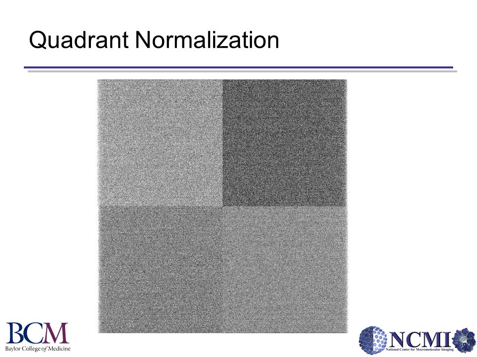
Final Practical Things to Remember… Good Normalization Means Good Data –Dark Reference –Gain Normalization –Quadrant Normalization Magnification Of CCD relative to Film Angstroms/Pixel

44
Normalization Standard Normalization Quadrant Normalization

46
Dark Reference

47
Gain Normalization

48
How Do I Tell If Something Is Wrong?

49
Magnification Of CCD relative to Film 2010F Mag x 1.38 = 2010F CCD Mag 3000SFF Mag x 1.41 = 3000SFF CCD Mag This has to be calibrated for each microscope detector.

50
How Do I Calculate Angstroms/Pixel? Å/pixel = Detector Step-Size/Magnification For a microscope magnification of 60,000 on the 3000SFF: Å /pixel = 150,000 Å / (microscope magnification x 1.41) Å /pixel = 150,000 Å / (60,000 x 1.41) Å /pixel = 1.77
 Å /pixel = 150,000 Å / (60,000 x 1.41) Å /pixel =")
51
Conclusion Understand what you are trying to achieve and use the detector that will make your job the easiest Check Your Own Data!

Similar presentations

 image>")


 COMS 4162, Lecture 3: Sampling and Reconstruction Ravi Ramamoorthi>")


