Download presentation
Presentation is loading. Please wait.

1
Module 9: TCP/IP Protocol Suite and IP Addressing
CCNA 1 Module 9: TCP/IP Protocol Suite and IP Addressing

2
TCP/IP – History and Future
Created by US DoD as a model able to withstand intense military attack and not fail. Data transmission was possible to any destination on the network under any circumstances.

3
TCP/IP – History and Future
Standardized in 1981 The TCP/IP model is now the standard on which the Internet is based. There are similarities and differences between the TCP/IP model and the nine layer OSI model.

4
TCP/IP Application Layer
Ensures that the data is properly packaged before being passed on. Handles high-level protocols, representation, encoding, and dialog control. Simple Network Management Protocol (SNMP) – allows network managers to manage configurations, statistics, performance, and security. Domain Name System (DNS) – used to translate domain names into IP addresses. Application
 – allows network managers to manage configurations, statistics, performance, and security. Domain Name System (DNS) – used to translate domain names into IP addresses. Application.")
5
TCP/IP Application Layer
Has protocols to support file transfer, , and remote login: File Transfer: Trivial File Transfer Protocol (TFTP) – unreliable, connectionless User Datagram Protocol (UDP) service used to transfer configuration files, Cisco IOS images, and to transfer files in a LAN. File Transfer Protocol (FTP) – reliable, connection-oriented service that uses TCP to transfer files between systems Network File System (NFS) – allows file access to a remote storage device such as a hard disk Application
 – unreliable, connectionless User Datagram Protocol (UDP) service used to transfer configuration files, Cisco IOS images, and to transfer files in a LAN. File Transfer Protocol (FTP) – reliable, connection-oriented service that uses TCP to transfer files between systems. Network File System (NFS) – allows file access to a remote storage device such as a hard disk. Application.")
6
TCP/IP Application Layer
Simple Mail Transfer Protocol (SMTP) – administers the transmission of plain text over computer networks. Remote access: Telnet –remotely access a computer, enabling a user to log into an Internet host and execute commands. A Telnet client is called a local host. A Telnet server is called a remote host. Application
 – administers the transmission of plain text over computer networks. Remote access: Telnet –remotely access a computer, enabling a user to log into an Internet host and execute commands. A Telnet client is called a local host. A Telnet server is called a remote host. Application.")
7
TCP/IP Transport Layer
Provides a logical connection between a source host and a destination host. Transport Layer protocols segment and reassemble data sent by applications, into the same data stream, between end points. Provides end-to-end control and reliability as data travels through the cloud, accomplished through: sequence numbers, acknowledgments and sliding windows. Transport

8
TCP/IP Transport Layer
I just sent #10 I just received #10 Now I need #11 Transport This shows sequence numbers and acknowledgements.

9
TCP/IP Transport Layer
Sliding Windows I just sent #11, 12 and 13 I just received #12 Now I need #13 Transport This indicates that packet 13 either did not arrive, or arrived with errors, and needs retransmission.

10
TCP/IP Transport Layer
Sliding Windows I just sent #13 and 14 I just received #14 Now I need #15 Transport The sliding window has worked as the last packet sent has arrived.

11
TCP/IP Transport Layer
The only Transport layer protocols are TCP and UDP. Transmission Control Protocol (TCP) Connection-oriented protocol End-to-end operation Flow control – sliding windows Reliability – sequence numbers and acknowledgments User Datagram Protocol (UDP) Connectionless Unreliable (no acknowledgments or error checking) Transport
 Connection-oriented protocol. End-to-end operation. Flow control – sliding windows. Reliability – sequence numbers and acknowledgments. User Datagram Protocol (UDP) Connectionless. Unreliable (no acknowledgments or error checking) Transport.")
12
TCP/IP Internet Layer Two purposes are determining the best path and packet-switching. No error checking or correction Protocols: Internet Protocol (IP) - connectionless, best-effort delivery routing of packets; determines best path to destination Internet Control Message Protocol (ICMP) – control and messaging Address Resolution Protocol (ARP) - determines the MAC address, for a known IP address. Reverse Address Resolution Protocol (RARP) - determines the IP address for a known MAC address. Internet
 - connectionless, best-effort delivery routing of packets; determines best path to destination. Internet Control Message Protocol (ICMP) – control and messaging. Address Resolution Protocol (ARP) - determines the MAC address, for a known IP address. Reverse Address Resolution Protocol (RARP) - determines the IP address for a known MAC address. Internet.")
13
TCP/IP Network Access Layer
Allows an IP packet to make a physical link to the network media Maps IP addresses to MAC addresses Encapsulates IP packets into frames Drivers for software applications, modem cards, and other devices operate at the network access layer. Serial Line Internet Protocol (SLIP) and Point-to-Point Protocol (PPP) provide network access. ARP and RARP also work at this layer. Network Access
 and Point-to-Point Protocol (PPP) provide network access. ARP and RARP also work at this layer. Network Access.")
14
Comparing TCP/IP and OSI
TCP/IP Model OSI Model 7 Application Application Layers Application 6 Presentation 5 Session Transport 4 Transport Internet 3 Network Data Flow Layers 2 Data Link Network Access 1 Physical

15
Comparing TCP/IP and OSI
Similarities Both have layers. Both have application layers, though they include different services. Both have comparable transport and network layers. Both use packet-switched instead of circuit-switched technology. Differences TCP/IP combines the OSI application, presentation, and session layers into its application layer. TCP/IP combines the OSI data link and physical layers into its network access layer. TCP/IP appears simpler as it has fewer layers. The TCP/IP transport layer uses UDP (not reliable) delivery of packets. The transport layer in the OSI model is always reliable.
 delivery of packets. The transport layer in the OSI model is always reliable.")
16
Internet Architecture
The Internet is based on the principle of network layer interconnection. This means that it is independent of the lower layers and the upper layers. This functionality allows for different Layer 1 and 2 LAN technologies (media; protocols; LAN design, etc.) It also allows for a diversity of applications at Layers 5, 6, and 7.
 It also allows for a diversity of applications at Layers 5, 6, and 7.")
17
Internet Architecture
This means that one network with one set of Layer 1 and 2 LAN media, design etc. and its own upper layer Applications can communicate with a very different LAN. This capability means that the Internet is scalable; now with over 90,000 core routers and 300 million users, and growing.

18
Internet Architecture

19
Internet Architecture
X and Y represent computers that are connected and that can communicate with each other from across the world.

20
Internetworking must have the following characteristics.
Internetworking- building network of networks. A network of networks is called “internet”. Internetworking must have the following characteristics. Scalable Handle the transport of data across vast distances Flexible Adjust to dynamic conditions on the network Cost-effective Permits anytime, anywhere data communications to anyone. An uppercase I is used to refer to the networks that grew out of the DoD on which the WWW runs, and to refer to the Internet.

21
Two routers connect three physical networks
Two routers connect three physical networks. Because all the users on all the networks want to communicate with each other, even without being directly connected to one another, the router must have some way of dealing with this.

22
The router needs to keep a list of all user computers and the paths to them. The router would decide whether and where to forward data packets based on this table of all users, forwarding based on the destination computer. This is not scalable system

23
Solution Two computers, anywhere in the world, following certain hardware, software, and protocol specifications, can communicate reliably (“anyplace/anytime/anyone”). Even when they are not directly connected ( or even not close to being directly connected).
. Even when they are not directly connected ( or even not close to being directly connected).")
24
IP Addressing

25
IP Addressing Each computer (computer interface) in a TCP/IP network must have two addresses: An IP (logical, layer 3) address, is a combination of the network address and the host address creating a unique address for each device on a network. This address is needed to deliver the packet to the correct network. A unique MAC (physical, layer 2) address. Once the data (packet) has arrived at the network, this address is needed to deliver it to the destination device.
 address, is a combination of the network address and the host address creating a unique address for each device on a network. This address is needed to deliver the packet to the correct network. A unique MAC (physical, layer 2) address. Once the data (packet) has arrived at the network, this address is needed to deliver it to the destination device.")
26
IP Addressing An IP address is a 32-bit sequence of ones and zeros.
It is commonly represented in dotted decimal format, as it is easier to understand and less prone to error.

27
Decimal and Binary Conversion
Review the binary to decimal and the decimal to binary conversions in 9.2.2

28
Address Classes A router uses the IP address of the destination network to deliver a packet to the correct network. Every IP address has two parts The first part identifies the network where the device is connected and the second part identifies the device. There are four octets, each ranging from 0-255, representing 256 possible addresses.

29
Address Classes An IP address is always divided up into a network portion and a host portion.

30
IP Address as a 32-Bit Binary Number

31
Binary and Decimal Conversion

32
Address Classes IP addresses are hierarchical, meaning an address can be referenced back to a particular group address.

33
Address Classes There are five address classes:
Class A – for very large networks Class B – for medium networks Class C – for small networks Class D – for multicast groups; no need for network and host parts Class E – for research purposes

34
Address Classes

35
Address Classes Learn these tables!

36
Address Classes One network octet and three host octets.
Class A: One network octet and three host octets. The first bit of a Class A address is 0. The lowest number that can be represented is , decimal 0. The highest number that can be represented is , decimal 127. Usable 1st octet addresses: (0 and 127 are reserved addresses)
")
37
Address Classes Two network octets and two host octets.
Class B: Two network octets and two host octets. The first two bits of a Class B address are 10. The lowest number that can be represented is , decimal 128. The highest number that can be represented is , decimal 191. Usable 1st octet addresses:

38
Address Classes Three network octets and one host octet.
Class C: Three network octets and one host octet. The first three bits of a Class C address are 110. The lowest number that can be represented is , decimal 192. The highest number that can be represented is , decimal 223. Usable 1st octet addresses:

39
Address Classes Class D: Created to enable multicasting. A destination address is a group of addresses. The first four bits of a Class D address must be 1110. The first octet range for Class D addresses is to , or 224 to 239.

40
Address Classes Reserved for IETF research. Not used on the Internet.
The first four bits of a Class E address are always 1111. The first octet range for Class E addresses is to , or 240 to 255.

41
What is the Address Class?
= = = = = = = = = = = = B C B A C A What do you notice about each of the Class addresses? What is common with the Class A addresses? What is common with the Class B addresses? What is common with the Class C addresses?

42
Address Classes This is a very important table.
Copy it into your journal. MEMORISE IT!

43
Reserved addresses Two addresses on any network cannot be used by hosts. Network address – Used to identify the network itself Broadcast address – Used for broadcasting packets to all the devices on a network The HOST bits of a network address are all 0s. The HOST bits of a broadcast address are all 1s.

44
Reserved addresses

45
Reserved addresses IP Address –10.18.127.100 Subnet Mask –
Network address = Broadcast address = The first question to ask is, ‘What class is this address?’ Class A

46
Reserved addresses IP Address –131.234.12.66 Subnet Mask –
Network address = Broadcast address = What class is this address? Class B

47
Reserved addresses IP Address –199.218.4.56 Subnet Mask –
Network address = Broadcast address = What class is this address? Class C

48
Reserved addresses IP Address – 210.189.137.100
Subnet Mask – Network address = Broadcast address = What class is this address? Class C

49
Reserved addresses IP Address – 180.43.120.39
Subnet Mask – Network address = Broadcast address = What class is this address? Class B

50
Network and Host Addressing

51
Network Address Host portion all zeros

52
Broadcast Address Host portion all ones

53
Public and Private Addresses
No two devices on the Internet can have the same IP address. Ensuring this does not happen is handled by the Internet Assigned Numbers Authority (IANA). With the growth of the Internet, available Internet addresses have nearly run out. To help deal with this problem, RFC 1918 sets aside three blocks of IP addresses for private, internal use.
. With the growth of the Internet, available Internet addresses have nearly run out. To help deal with this problem, RFC 1918 sets aside three blocks of IP addresses for private, internal use.")
54
Required Unique Address
A packet can only be sent out onto the Internet if it has a unique address Both networks have a network address when data transmissions reach the router, which network would it forward to???

55
Public and Private Addresses
One Class A, a range of Class B addresses, and a range of Class C addresses are not routed on the Internet. – – – A router uses Network Address Translation (NAT) to translate private addresses to public addresses.
 to translate private addresses to public addresses.")
56
Public and Private Addresses
If you are addressing a test lab or a home network, these private addresses can be used instead of globally unique addresses. Private addresses can be intermixed with public IP addresses as shown in the figure.

57
Subnets Subnetting a network means to use the subnet mask to divide a up a network into smaller, segments, or subnets. Subnetting has prevented the wasting of usable host addresses. To create a subnet address, some bits from the host field are borrowed, and designated as subnet bits.

58
The following figure shows a Class B network (131. 108
The following figure shows a Class B network ( ) divided into three subnetworks.
 divided into three subnetworks")
59
Subnetworks

60
Subnet Mask Determines which part of an IP address is the network field and which part is the host field Follow these steps to determine the subnet mask: Express the subnetwork IP address in binary form. Replace the network and subnet portion of the address with all 1s. Replace the host portion of the address with all 0s. Convert the binary expression back to dotted-decimal notation.

61
Subnet Mask Subnet mask in decimal =

62
Boolean Operations: AND, OR, and NOT
AND is like multiplication. OR is like addition. NOT changes 1 to 0, and 0 to 1.

63
Performing the AND Function

64
Range of Bits Needed to Create Subnets

65
Subnet Addresses

66
Decimal Equivalents of 8-Bit Patterns

67
Creating a Subnet Determining subnet mask size
Computing subnet mask and IP address Computing hosts per subnetwork Boolean AND operation IP configuration on a network diagram Host and subnet schemes Private addresses

68
Determining Subnet Mask Size
Class B address with 8 bits borrowed for the subnet (8 bits borrowed for subnetting) routes to subnet rather than just to network
 routes to subnet rather than just to network")
69
Determining Subnet Mask Size
Class C address with a subnet mask of (3 bits borrowed) 100 00011 Network Field SN Host Field The address would be on the subnet
 Network Field. SN. Host Field. The address would be on the subnet")
70
Subnetting Example with AND Operation

71
IP Configuration on a Network Diagram
The router connects subnetworks and networks.

72
IPv4 vs IPv6 Class A and Class B addresses make up three quarters of the four billion possible addresses. These are virtually used up. Class C addresses only allow 254 hosts, too small for many organisations. In 1992 the Internet Engineering Task Force (IETF) began work on IP version 6.
 began work on IP version 6.")
73
IPv4 vs IPv6 IPv4 addresses are 32 bits long.
IPv6 addresses are assigned to interfaces, not nodes. IPv6 addresses are written in hexadecimal, and separated by colons.

74
IPv4 vs IPv6

75
Obtaining an IP Address

76
Obtaining an IP Address
IP addresses can be assigned statically or dynamically. Static addressing is manually done by a system administrator. Best on small, infrequently changing networks. Good record-keeping is essential. Servers, printers and routers should be given static addresses. Static addressing is NOT scalable.

77
RARP IP Addressing Reverse Address Resolution Protocol (RARP) associates a known MAC addresses with an IP addresses. IP source addresses are needed for the address field in all IP packets. A RARP server must be present. RARP requests are broadcast onto the LAN and are responded to by the RARP server, usually a router.

78
RARP Example

79
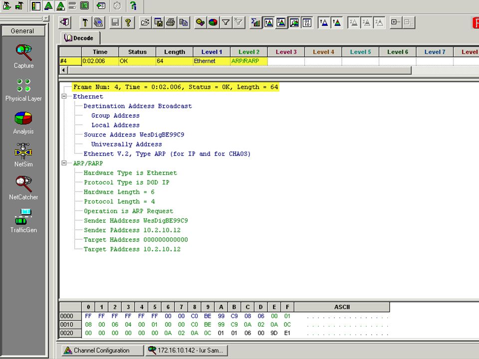
ARP/RARP Message Structure
Return to Page 400 in the Book for more details

81
BOOTP IP Addressing Operates in a Client-Server environment.
Unlike BOOTP was not designed for dynamic address assignment. The administrator must maintain the BOOTP database with profiles for each host. BOOTP is used when a device starts up. BOOTP uses UDP to carry messages. BOOTP sends a broadcast IP packet. A BOOTP server receives the broadcast and then sends back a broadcast.

82
DHCP IP Addressing DHCP has replaced BOOTP.
DHCP allows a host to obtain an IP address dynamically without needing an individual profile for each device. All that is needed is a defined range of IP addresses on a DHCP server. Information sent includes the subnet mask and the leased address. Users can be mobile and keep the same address. DHCP offers a one to many ratio of IP addresses, and that an address is available to anyone who connects to the network.

83
Address resolution A datagram on a LAN must contain both a destination MAC address and a destination IP address. These addresses must be correct and match the destination MAC and IP addresses of the host device. If it does not match, the datagram will be discarded by the destination host.

84
ARP – Address Resolution Protocol
ARP tables store MAC and IP addresses of other LAN devices. Maintained automatically Stored in RAM

85
ARP – Address Resolution Protocol
Two ways to gather MAC addresses: Monitor traffic and record the addresses Broadcast an ARP request An ARP request is used if a device needs an IP and MAC address pair. The broadcast is sent If the device exists and is on line, it will reply. If the device does not exist or is turned off, there is no response to the ARP request. In this situation, the source device reports an error.

86
Proxy ARP A router sends an ARP response with the MAC address of the interface on which the request was received, to the requesting host. This is done for addresses not in local subnet.

87
Default Gateway The IP address of the router interface is stored in the network configuration of the host. The source host compares the destination IP address and its own IP address to determine if the two IP addresses are located on the same segment. If the receiving host is not on the same segment, the source host sends the data using the actual IP address of the destination and the MAC address of the router. Either Proxy ARP or the Default Gateway must be configured, or no traffic can leave the LAN.

88
Do lab 9.2.7 Do lab at home

89
Good luck on the exam……..

Similar presentations


. Overview A router is a type of internetworking device that passes data packets between networks based on Layer 3 addresses. A.>")
>")