Download presentation
Presentation is loading. Please wait.

1
PS fork equipped with 8 semiconductor (4 by arm) strain gauges
 strain gauges")
2
G1 G2 G3 G4 G5 G6 G7 G8 10 50 77 10 50 77 26 Gauges location Gauges G4 and G8 are bonded in the fork shaft Gauges G2, G3, G6 and G7 are bonded in the wings of the arms of the fork Gauges G1 and G5 are bonded in the flexible flat parts of the fork

3
Gauges location Gauges G4 and G8 are mainly sensitive to the twist of the shaft in X axis Gauges G2, G3, G6 and G7 are mainly sensitive to the deflections in Z direction Gauges G1 and G5 are mainly sensitive to the deflections in X direction G1 G2 G3 G4 G5 G6 G7 G8 10 50 77 10 50 77 26 X Y Z

4
Gauges location G4 G2 G3 G1 Gauges location in the right arm of the fork. Gauges located in the left arm are symmetric to these gages as follow: G1 and G5 G2 and G6 G3 and G7 G4 and G8

5
Gauges location IN OUT POSITION IN POSITION The strain gauges G2, G3, G6 and G7 are located in this side of the fork IN movement produces compression (resistance decrease) in gauges G2, G3, G6 and G7. OUT movement produces extension (resistance increase) in gauges G2, G3, G6 and G7.
 in gauges G2, G3, G6 and G7..")
6
The following setup has been built in order to calibrate the strain gauges installed on the fork. The goal of the calibration process is to collect the suitable data about the behaviour of the system to reproduce the deformations on the fork during the scan by mean of the variation of resistance measured in the strain gauges.

7
2 3 5 4 A progressively increased known load is applied in this point of the arm and the deflections in the fork are measured by means of 4 dial indicators Gauges calibration - Deflection measurements Shows the setup for gauges calibration in the right are of the fork, an equivalent setup has been used in the left arm of the fork.

8
2 3 4 5 Gauges calibration - Deflection measurements

9
A lever fixed to the fork axis provides information about the twist of the fork shaft. Gauges calibration - Deflection measurements

10
d1 d2 d9 50 d3 d6 d7 d8 d10 d4 d5 30 35 48 Gauges calibration - Deflection measurements

11
Typical gauge calibration plot

12
Gauges calibration - Deflection measurements Typical gauge calibration plot

13
Tension variation the right arm gauges IN movement Results

14
Tension variation the right arm gauges OUT movement Results

15
Displacement in point d1 based in the variation of resistance of G1, IN movement. Displacement in point d2 based in the variation of resistance of G3, IN movement. Results

16
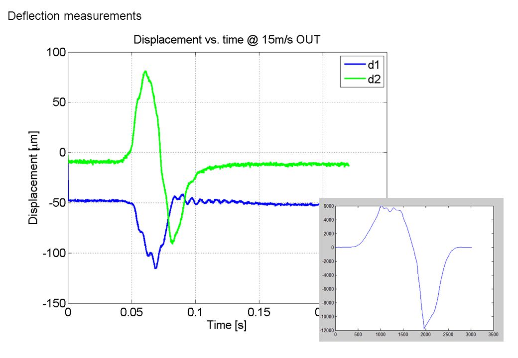
Displacement in point d1 based in the variation of resistance of G1, OUT movement. Displacement in point d2 based in the variation of resistance of G3, OUT movement. Results

17
Deflection measurements

19
Next Perform measurement in the 2 nd arm Perform measurement in both arms at the same time with and without wire Find correlation between displacements in the arms and the pattern of movement Perform measurements in vacuum on both arm and wire resistance Perform measurements using a more rigid fork Introduce measure data in an analytical model of the wire to find a correlation between wire resistance variation and wire elongation due to vibrations Compare different motion patterns

Similar presentations

 1 Instrumentation Dr. Xiaofeng Wu.>")


 1 Instrumentation Dr. Xiaofeng Wu.>")


 Stress δ & ε Curve Cantilever Strain gage Gage factor Problem solution.>")

 Translations and Rotations Stresses Material Properties.>")