Download presentation
Presentation is loading. Please wait.

1
BASIC MECHANICAL ENGINEERING
UNIT VI MACHINE TOOLS

2
MACHINE TOOL Machine tool generally means a metal cutting machine.
A machine tool is a power driven device used for shaping, sizing or processing a product to a desired accuracy by removing the excess material in the form of chips. The basic machining operations are turning, drilling, shaping etc… The machine tools have some essential features common to all of them, that is they have a basic structure to which are attached work holding and tool holding devices, arrangements for giving movements to the work piece and the tool for the depth of cut, cutting speed and feed and a drive.

3
There are several types of Special purpose machine tools and Standard machine tools.
Special purpose machine tools are meant for specific operations or jobs such as gear cutting machines, thread grinding machines, transfer machines or machining centers. This type of machine tools are designed for only a limited number of operations. They are costlier and suited for large volume of production only. Standard machine tools are general purpose machine tools capable of performing a number of operations. Types of Standard machine tools are: Lathe machine, A drilling machine Shaper machine Milling machine and A grinding machine…..

4
WORKING MOTIONS FOR SOME MACHINE TOOLS
LATHE DRILLING

5
SHAPING MILLING

6
GRINDING

7
CUTTING TOOL A cutting tool has one or more sharp cutting edges and is made of a material that is harder than the work material. The cutting edge serves to separate a chip from the parent work material. There are two basic types, (a) single-point tools and (b) multiple-cutting-edge tools.
 single-point tools and. (b) multiple-cutting-edge tools.")
8
A single-point tool has one cutting edge and is used for operations such as turning.
Multiple-cutting-edge tools have more than one cutting edge and usually achieve their motion relative to the work part by rotating. Drilling and milling use rotating multiple-cutting-edge tools.

9
LATHES Lathes are turning machines. LATHE MACHINE

10
Their basic operation involves rotating a work piece and traversing a sharp cutting tool across its length. Lathe is one of the most widely used machine tools in metal cutting works. These are basically designed to cut cylindrical metal stock and are able to produce screw threads, tapered work, drilled holes. It is used for machining the job (work piece) which is rotated and a cutting tool is fed to cause the cutting action.
 which is rotated and a cutting tool is fed to cause the cutting action.")
11
Classification of lathe:
Bench lathe Speed lathe Centre lathe Tool room lathe Turret lathe Capstan lathe Automatic lathe CNC lathe

12
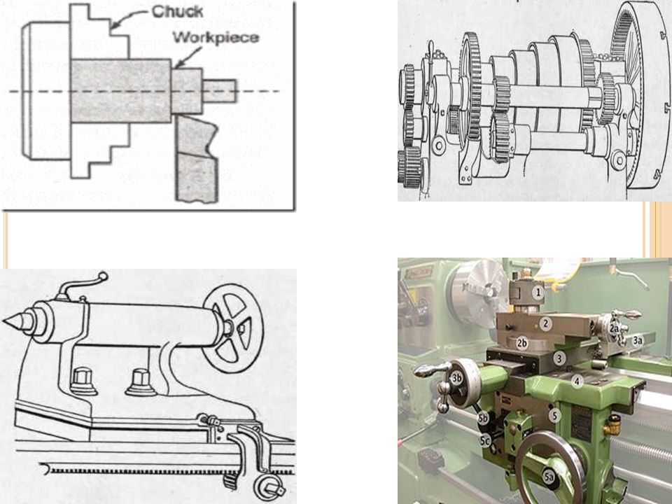
MAIN PARTS OF LATHE : LATHE MACHINE

13
MAIN PARTS OF LATHE : Bed Head Stock Tail Stock Carriage Or Tool Post

16
Machining operations other than turning that are performed on a lathe:
Facing, Turning or Taper Turning, Thread cutting, Knurling, Drilling, Reaming Parting or cutting off Boring and Grooving

19
Advantages: Variety of work materials. Variety of part shapes and geometric features. Dimensional accuracy. Good surface finishes. Disadvantages: Wasteful of material. Time consuming.

20
SHAPER MACHINE Shaping and planing are similar operations, both involving the use of a single-point cutting tool moved linearly relative to the work part. In conventional shaping and planing, a straight, flat surface is created by this action. The difference between the two operations is, in shaping the speed motion is accomplished by moving the cutting tool; while in planing, the speed motion is accomplished by moving the work part.

21
SHAPER :-

23
WORKING PRINCIPLE OF SHAPER
A single point cutting tool is held in the tool holder, which is mounted on the ram. The work piece is rigidly held in a vice or clamped directly on the table. The ram reciprocates and thus cutting tool held in tool holder moves forward and backward over the work piece. In a standard shaper, cutting of material takes place during the forward stroke of the ram. The backward stroke remains idle and no cutting takes place during this stroke.

24
The feed is given to the work piece and depth of cut is adjusted by moving the tool downward towards the work piece. The time taken during the idle stroke is less as compared to forward cutting stroke and this is obtained by quick return mechanism.

25
Components of a shaper

26
Types of shapes that can cut by shaping and planing:
V groove, Square groove, T-slot, dovetail slot, and gear teeth.

27
Reciprocating type of machine tool - used for machining prismatic components
Job is rigidly held in work holding device- tool held in tool post mounted on the ram of the machine – ram reciprocated to and fro and makes the tool to cut the material in forward stroke No cutting of material in return stroke (Idle stroke) Forward stroke is cutting stroke Return stroke is idle stroke
 Forward stroke is cutting stroke. Return stroke is idle stroke.")
28
PRINCIPAL PARTS OF SHAPER
Base Column Cross-Rail Table Ram Tool head Vice

29
Classification of shapers
Based on length of the stroke, type of driving mechanism etc shapers are classified as.. Horizontal shaper Universal shaper Vertical shaper Geared shaper Crank shaper Hydraulic shapers

30
Shaper operations The basic operations done on shaper are:
Horizontal cutting Vertical cutting Angular cutting Irregular cutting

31
SHAPING MACHINE Cutting tool in action Photographic view of a shaping machine

32
Drilling Machine

33
Drilling Machine Drilling is a machining operation used to create a round hole in a work part. . Drilling is usually performed with a rotating cylindrical tool that has two cutting edges on its working end. The tool is called a drill or drill bit. The rotating drill feeds into the stationary work part to form a hole whose diameter is equal to the drill diameter.

34
WORKING PRINCIPLE OF DRILLING MACHINE
Twist drill is the most widely used tool in modern drilling practice. It consists of a cylindrical body carrying two spiral flutes cut on it. The twist drill consists of two main parts i.e, a shank, which is gripped in the drill chuck or sleeve, and the other the body which forms the main cutting unit. WORKING PRINCIPLE OF DRILLING MACHINE The rotating edge of the drill exerts a large force on the work piece and the hole is generated. The removal of metal in a drilling operation is by shearing and extrusion.

35
Two hole types: (a) through hole and (b) blind hole.
 through hole and (b) blind hole.")
36
1. Base 2. Column 3. Radial arm 4. Motor for elevating arm 5. Elevating screw 6. Guide ways 7. Motor for driving d rill spindle 8. Drill head 9. Drill spindle 10. Table

37
Main operating parts of drill machine
Base Column Table Drilling head

38
Types of Drill Machines
Portable drilling machine Sensitive or bench drill drilling machine Radial drilling machine Deep hole drilling machine Gang drilling machine Multiple spindle drilling machine Horizontal drilling machine Automatic drilling machine

40
OPERATIONS DONE ON DRILLING MACHINE
Machining operations related to drilling: Drilling, Reaming, Boring , Counter-boring, Counter-sinking , spot facing and Tapping.

41
Drilling operations :-
Drilling & boring

42
Reaming & tapping

44
Milling Machine Milling is a machining operation in which a work part is fed past a rotating cylindrical tool with multiple cutting edges, The axis of rotation of the cutting tool is perpendicular to the direction of feed. The cutting tool in milling is called a milling cutter and the cutting edges are called teeth. The conventional machine tool that performs this operation is a milling machine.

45
The geometric form created by milling is a plane surface.
Variety of shapes possible, high production rates, one of the most versatile, widely used machining operations.

46
PRINCIPLE OF MILLING In milling machine, the metal is cut by means of a rotating cutter having multiple cutting edges. For cutting operation, the work piece is fed against the rotary cutter. As the work piece moves against the cutting edges of milling cutter, metal is removed in form chips. Machined surface is formed in one or more passes of the work.

47
Two basic types of milling operations: (a) peripheral or plain milling and (b) face milling.
 peripheral or plain milling and (b) face milling.")
48
In peripheral milling, also called plain milling, the axis of the tool is parallel to the surface being machined, and the operation is performed by cutting edges on the outside periphery of the cutter. In face milling, the axis of the cutter is perpendicular to the surface being milled, and machining is performed by cutting edges on both the end and outside periphery of the cutter.

49
Types of Milling Machines
Column and knee type milling machines Fixed-bed type milling machine Planer milling machine Production milling machines Special purpose milling machines

50
Principal parts of milling machine
Base Column Knee Saddle Table Over arm Arbor support Elevating screw.

51
Horizontal Milling :-

52
Vertical milling :-

53
MILLING OPERATIONS Plain or Slab milling Face milling Angular milling
Form milling Straddle milling Gang milling

56
Peripheral milling: (a) slab milling, (b) slotting, (c) side milling, (d) straddle milling, and (e) form milling.
 slab milling, (b) slotting, (c) side milling, (d) straddle milling, and (e) form milling.")
57
Face milling: (a) conventional face milling, (b) partial face milling, (c) end milling, (d) profile milling, (e) pocket milling, and (f) surface contouring.
 conventional face milling, (b) partial face milling, (c) end milling, (d) profile milling, (e) pocket milling, and (f) surface contouring.")
58
Tool geometry elements of an 18-tooth plain milling cutter.

59
Milling operations :- Pockets & chamfering

60
Flat surfaces

61
GRINDING MACHINE :-

62
GRINDING MACHINE :-

63
Abrasive Processes Abrasive machining involves material removal by the action of hard, abrasive particles that are usually in the form of a bonded wheel. Grinding is the most important abrasive process. Other traditional abrasive processes include honing, lapping, super finishing, polishing, and buffing. The abrasive machining processes are generally used as finishing operations

64
They can be used on all types of materials ranging from soft metals to hardened steels and hard non metallic materials such as ceramics and silicon. Some of these processes can produce extremely fine surface finishes, to μm. For certain abrasive processes, dimensions can be held to extremely close tolerances.

65
Grinding Grinding is a material removal process accomplished by abrasive particles that are contained in a bonded grinding wheel rotating at very high surface speeds. The grinding wheel is usually disk-shaped, and is precisely balanced for high rotational speeds. A grinding wheel consists of abrasive particles and bonding material.

66
The bonding material holds the particles in place and establishes the shape and structure of the wheel. The projected abrasive particles act like cutting tool tips and remove metal. Cutting edge becomes dulled and eventually get cracked. This process continues till the abrasive grains get worn out till the level of bond

67
Bond allows the remainder of the worn grains to be torn from the wheel exposing new grains.

68
WORKING PRINCIPLE OF GRINDING
A grinding wheel consists of abrasive particles, bonding material and voids. The projecting abrasive particles acts like cutting tool tips and remove metal where a properly selected grinding wheel exhibits self-sharpening action. As cutting proceeds, the abrasive particles at cutting edge become cracked along the cleavage planes due to resistance offered by work piece metal which resists the cutting action.

69
WORKING PRINCIPLE OF GRINDING
This process continues till the abrasive grains get worn down till the level of bond. At this point the bond allows the remainder of the worn grains to be torn from the wheel, exposing new grains which were previous below the surface of the wheel and the new grains do further cutting action.

70
Types of Grinding Machines
Rough grinding or non precision grinding Floor stand or bench grinders Portable grinders Swing frame grinders Abrasive belt grinders Precision grinding Cylindrical grinders Internal grinders Surface grinders Tool and cutter grinders Special grinding machines

71
PRINCIPAL PARTS OF A GRINDING MACHINE

72
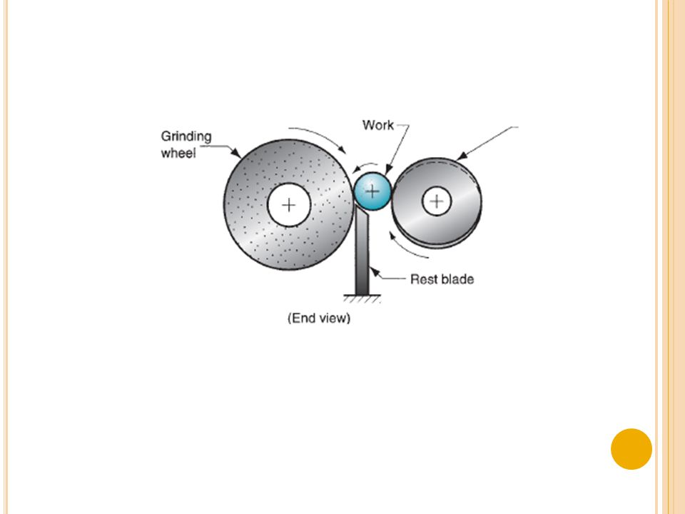
METHODS OF GRINDING Cylindrical grinding. Internal grinding.
Surface grinding. Face grinding. Form grinding. Centre less grinding. Snagging grinding. Off-hand grinding.

75
NUMERICAL CONTROL OF MACHINE TOOLS
Numerical control (NC) has been developed out of the need for higher productivity, lower cost and most precise manufacturing. In NC systems, operation instructions are inputted to the machine as numbers which are suitably cooled for storing on tapes. These instructions are then automatically carried out in the machine tool in predetermined sequence with pre-set or self-adjusted speed, feed etc with out human intervention. The definition of NC given by electronic industries association (EIA) – “A system in which actions are controlled by direct insertion of numerical data at some point. The system must automatically interpret at least some portion of this data.”
 has been developed out of the need for higher productivity, lower cost and most precise manufacturing. In NC systems, operation instructions are inputted to the machine as numbers which are suitably cooled for storing on tapes. These instructions are then automatically carried out in the machine tool in predetermined sequence with pre-set or self-adjusted speed, feed etc with out human intervention. The definition of NC given by electronic industries association (EIA) – A system in which actions are controlled by direct insertion of numerical data at some point. The system must automatically interpret at least some portion of this data.")
76
Numerical control (NC) is a form of programmable automation in which the mechanical actions of a piece of equipment are controlled by a program containing coded alphanumeric data. The operating principle of NC is to control the motion of the work head relative to the work part and to control the sequence in which the motions are carried out. A programme is prepared which consists of blocks, blocks consisting of combination of characters and numbers in sequence describing the position of the tool and job, the cutting speed and feed. The data converted into coded instructions which are called a Part Programme. As the job changes, the instructions of part program are also changed.

79
Basic Components of NC Machines
Program of instruction Controller unit Machine tool

80
Program of instruction
Serves as the input to the control unit which commands the machine tool to be controlled. Detailed step by step procedure which instructs the machine tool what to do. Input media can be punched cards/ magnetic disks or tape/ punched tape. Manual entry (MDI) Direct link to the computer (DNC)
 Direct link to the computer (DNC)")
81
Controller unit Consists of electronics and hardware that read and interpret the instructions Instructions are converted into mechanical actions of the machine tool Elements are 1.tape reader 2. data buffer 3. signal output to machine tool 4. feedback channel from M/C tool and 5. data decoding control area

82
Machine tool The machine tool consists of the worktable, spindle cutting tools, work fixtures, motors and controls and other equipment needed in the machining operation. NC machining centre is an automated production equipment which can perform various operations and has special features like automatic tool changer (ATC) and automatic pallet hanger (APC) which contribute to enhanced productivity.
 and automatic pallet hanger (APC) which contribute to enhanced productivity.")
83
Advantages Higher machine utilisation
Machining functions can be easily changed Human error is reduced Scrap rate and rework is reduced Design changes an be easily incorporated Can perform various operations Increased versatility and reliability

84
Disadvantages Requires high initial cost Maintenance costs are high
Skilled and experienced persons Punched tapes are least reliable components Costly controller systems are utilised in the machines

85
APPLICATIONS Metal removal process like milling, drilling, boring, turning, grinding etc. Press working machine tools. Welding machines. Inspection machines. Assembly machines. Tube bending. Flame cutting. Laser beam processes.

Similar presentations