Download presentation
Presentation is loading. Please wait.

1
Water Pumps

2
Definition Water pumps are devices designed to convert mechanical energy to hydraulic energy. They are used to move water from lower points to higher points with a required discharge and pressure head. This chapter will deal with the basic hydraulic concepts of water pumps

3
Pump Classification Turbo-hydraulic (kinetic) pumps
Centrifugal pumps (radial-flow pumps) Propeller pumps (axial-flow pumps) Jet pumps (mixed-flow pumps) Positive-displacement pumps Screw pumps Reciprocating pumps
 Propeller pumps (axial-flow pumps) Jet pumps (mixed-flow pumps) Positive-displacement pumps. Screw pumps. Reciprocating pumps.")
4
This classification is based on the way by which the water leaves the rotating part of the pump.
In radial-flow pump the water leaves the impeller in radial direction, while in the axial-flow pump the water leaves the propeller in the axial direction. In the mixed-flow pump the water leaves the impeller in an inclined direction having both radial and axial components

5
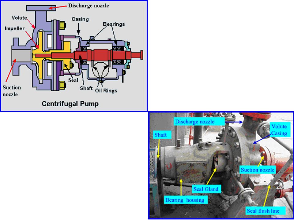
Schematic diagram of basic elements of centrifugal pump

6
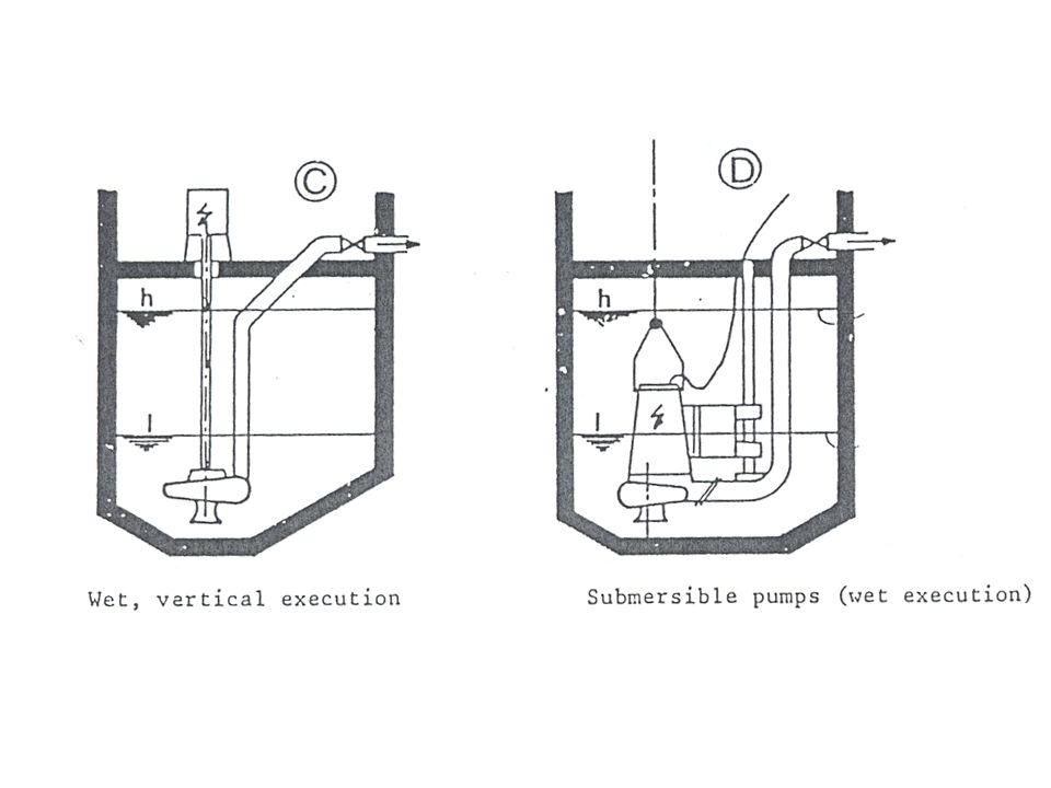
Schematic diagram of axial-flow pump arranged in vertical operation

7
Screw pumps. In the screw pump a revolving shaft fitted with blades rotates in an inclined trough and pushes the water up the trough.

9
Reciprocating pumps. In the reciprocating pump a piston sucks the fluid into a cylinder then pushes it up causing the water to rise.

10
Centrifugal Pumps Demour’s centrifugal pump - 1730 Theory
conservation of angular momentum conversion of kinetic energy to potential energy Pump components rotating element - impeller encloses the rotating element and seals the pressurized liquid inside – casing or housing

11
Centrifugal Pumps Broad range of applicable flows and heads
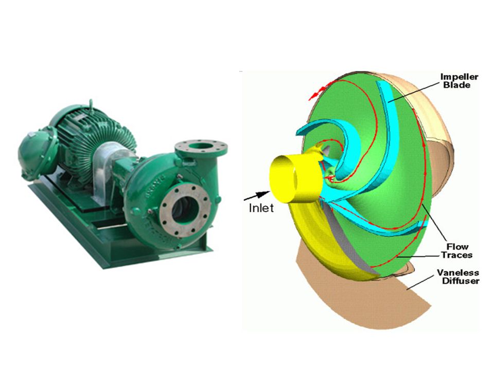
Higher heads can be achieved by increasing the diameter or the rotational speed of the impeller Impeller Vanes Casing Suction Eye Discharge Flow Expansion

12
Centrifugal Pump: Centrifugal pumps (radial-flow pumps) are the most used pumps for hydraulic purposes. For this reason, their hydraulics will be studied in the following sections.
 are the most used pumps for hydraulic purposes. For this reason, their hydraulics will be studied in the following sections.")
15
Main Parts of Centrifugal Pumps
Impeller: which is the rotating part of the centrifugal pump. It consists of a series of backwards curved vanes (blades). The impeller is driven by a shaft which is connected to the shaft of an electric motor.
. The impeller is driven by a shaft which is connected to the shaft of an electric motor.")
16
Main Parts of Centrifugal Pumps
Casing Which is an air-tight passage surrounding the impeller designed to direct the liquid to the impeller and lead it away Volute casing. It is of spiral type in which the area of the flow increases gradually.

17
Suction Pipe. Delivery Pipe. The Shaft: which is the bar by which the power is transmitted from the motor drive to the impeller. The driving motor: which is responsible for rotating the shaft. It can be mounted directly on the pump, above it, or adjacent to it.

18
Note that a centrifugal pump can be either submersible (wet) or dry.
 or dry.")
20
Hydraulic Analysis of Pumps and Piping Systems
Pump can be placed in two possible position in reference to the water levels in the reservoirs. We begin our study by defining all the different terms used to describe the pump performance in the piping system.

Similar presentations