Download presentation
Presentation is loading. Please wait.

1
Gas Turbine engines

5
Compressors

6
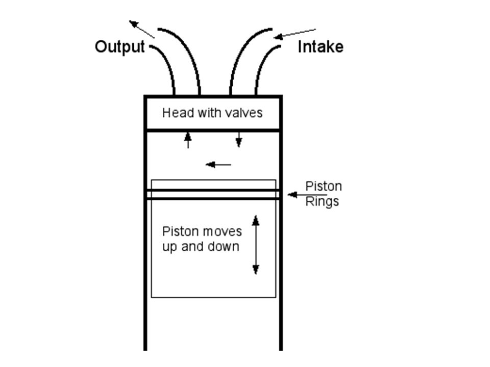
Types of Compressors Reciprocating air compressors are the type of compressor found in most small shops, they are positive displacement machines. This means that they increase the pressure of the air by reducing its volume, this is accomplished by a piston moving up a cylinder compressing the air above it. Single-stage and two-stage reciprocating compressors are commercially available. Single-stage compressors are generally used for pressures in the range of 70 psi to 150 psi. Two-stage compressors are generally used for higher pressures.

8
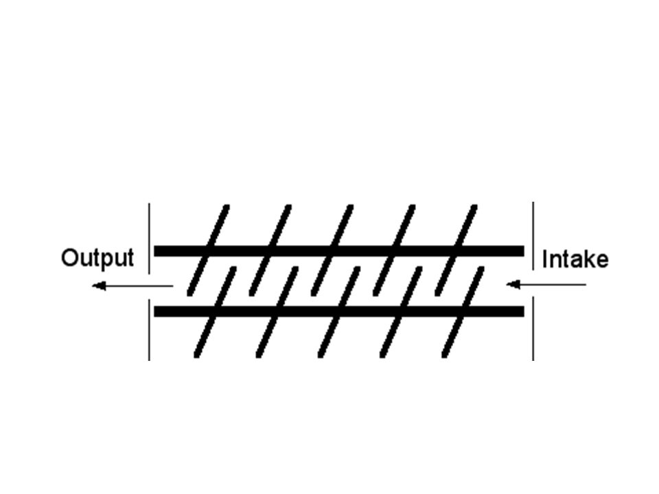
Rotary Screw Compressors
Rotary air compressors are also positive displacement compressors. The most common rotary air compressor is the single stage helical or spiral lobe oil flooded screw air compressor, consisting of two rotors within a casing where the rotors compress the air internally. There are no valves. These units are basically oil cooled with the oil sealing the internal clearances. Since the cooling takes place right inside the compressor, the working parts never experience extreme operating temperatures making them continious duty compressors.

10
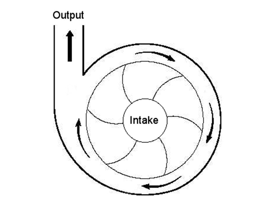
Centrifugal Compressors
The centrifugal air compressor is a dynamic compressor which depends on a rotating impeller to compress the air. In order to do this efficiently, centrifugal compressors must rotate at higher speeds than the other types of compressors. These types of compressors are designed for higher capacity because flow through the compressor is continuous and oil free by design.

12
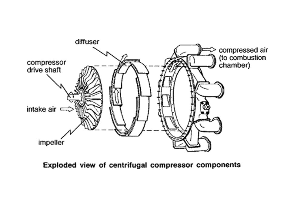
Centrifugal compressors consist of three main parts, as shown in Figure 1.
The first is a rotating impeller, which imparts work to the gas by increasing its angular momentum. The fluid static pressure and absolute velocity (stationary frame of reference) increase through the impeller passage. The second component is the diffuser section, often with vanes to increase the effectiveness. The diffuser converts the kinetic energy into the static pressure by decelerating the fluid.
 increase through the impeller passage. The second component is the diffuser section, often with vanes to increase the effectiveness. The diffuser converts the kinetic energy into the static pressure by decelerating the fluid.")
13
The third and final component is a volute or collector, used for collecting the gas from diffuser and delivering to the outlet pipe. A volute has two functions: collection and diffusion. The volute must collect and transport the fluid to the downstream system. It also raises the static pressure by converting kinetic energy (ρu2) to potential energy (static pressure). The latter function has performance benefits, as the discharge pressure is increased.
 to potential energy (static pressure). The latter function has performance benefits, as the discharge pressure is increased.")
14
Figure 1: Centrifugal compressor layout
Figure 1: Centrifugal compressor layout. (a) A cross-sectional view, showing the impeller followed by a vaned diffuser, and a volute. (b) An isometric view of the package.
 A cross-sectional view, showing the impeller followed by a vaned diffuser, and a volute. (b) An isometric view of the package.")
15
Examples of Application
Impeller of a compressor

16
Examples of Application
Vaned diffuser for centrifugal compressor

17
Examples of Application
Turbo charger

20
Axial Compressor

Similar presentations


 Barrow.>")


