Download presentation
Presentation is loading. Please wait.

1
Optimum Layout for a Turbofan Engine
P M V Subbarao Professor Mechanical Engineering Department An excellent Choice for Fighter Planes ….

2
Mixed Flow Turbofan Engine
6c 2 3 1 8 6h 7 4 5

3
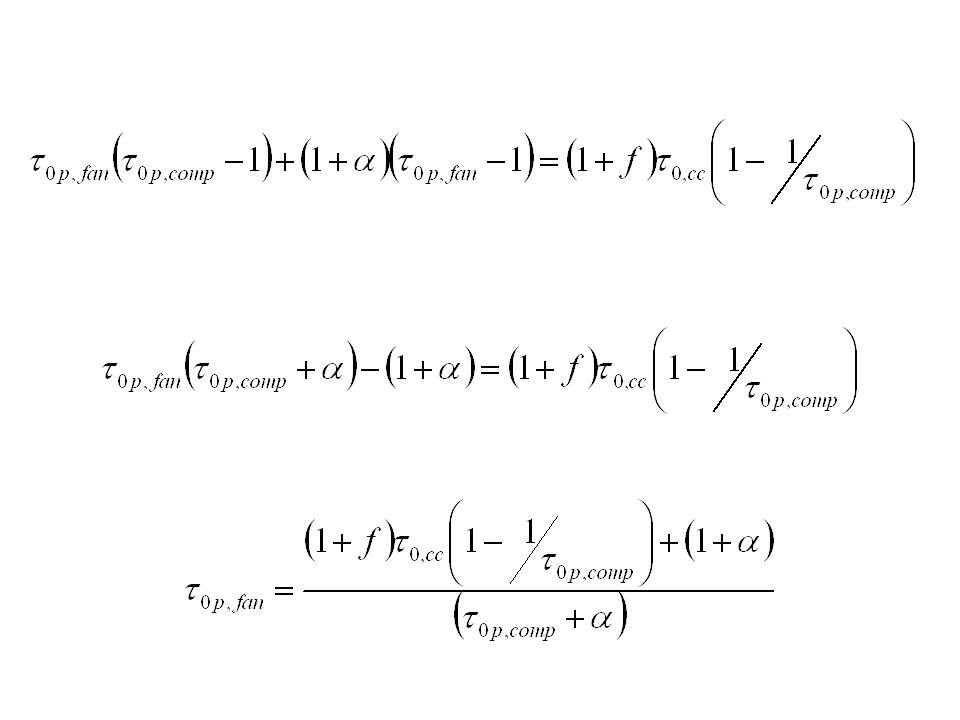
Ideal Mixer Ideal Mixer : Constant Total Pressure Process.
For a stable operation of the mixer, the inlet static pressures of core flow and fan flow must be equal. If they are not, back flow will occur in either the fan or core. The stagnation pressure ratio across the fan:

4
1 2 3 6c 8 5 7 4 6h

5
Condition for Efficient Mixing

6
Theory of Jet Propulsion : Just Enough Work
The power inputs to the compressor & fan = The power output of the turbine

8
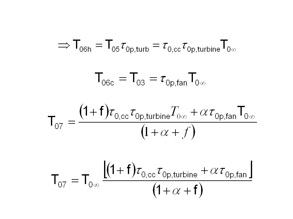
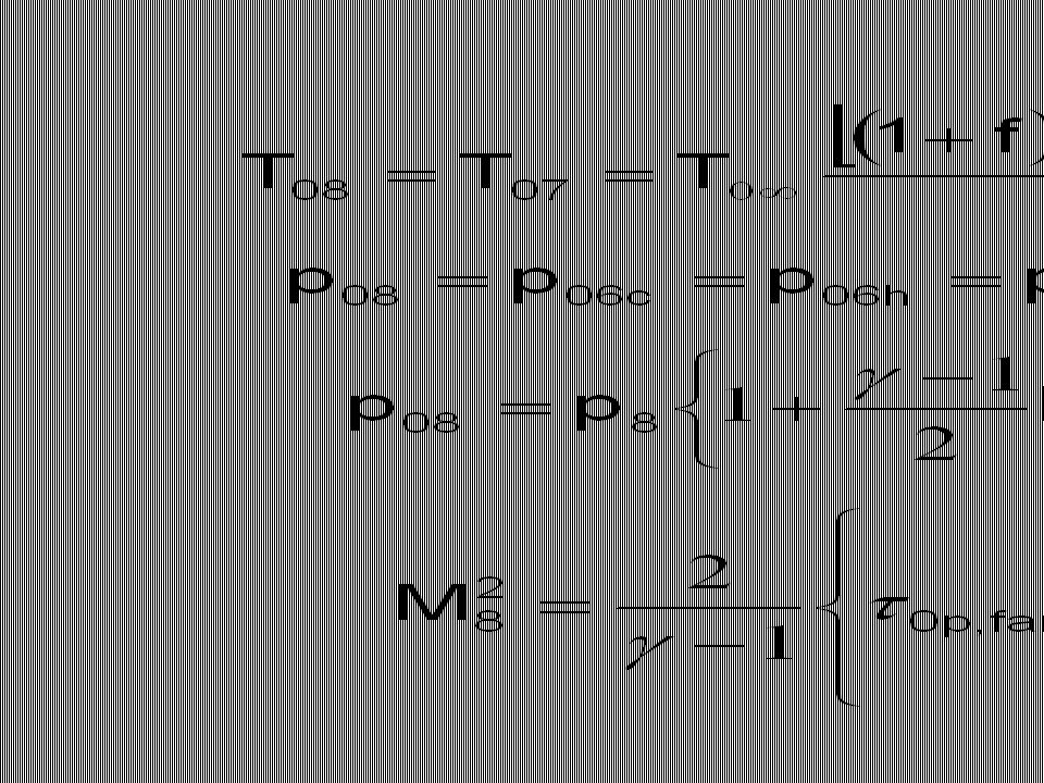
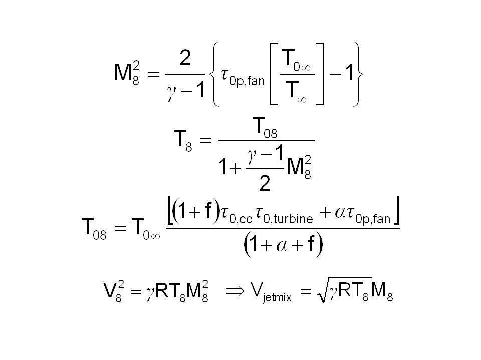
Adiabatic mixing process:

10
Mixed Flow Turbofan w/o AB
1 2 3 6c 8 5 7 4 6h

13
Generation of Thrust : The Capacity
Propulsive Power or Thrust Power: Specific Thrust based on total jet flow S,

14
Thrust Specific Fuel Consumption TSFC

15
Aviation Appreciation
Propulsion Efficiency

16
Mixed –Flow Fan : Effect of Bypass Ratio
r0p,comp=15 Mac=0.75 t0,cc=5.78 Non-dimensional TSFC Non-dimensional Specific Thrust

17
Subsonic Operation : Mixed Turbo Fan: Mac=0.75
Fan Pressure Ratio Bypass Ratio Compressor Pressure Ratio

18
Supersonic Operation : Mixed Turbo Fan: Mac=2.0
Fan Pressure Ratio 2 Bypass Ratio 3 4 5 Compressor Pressure Ratio

19
Subsonic Operation : Mixed Turbo Fan: Mac=0.75
Fan Pressure Ratio 5 TSFC 4 3 2 Compressor Pressure Ratio

20
Subsonic Operation : Mixed Turbo Fan : Mac=0.75
Fan Pressure Ratio 2 3 Specific Thrust 4 5 Compressor Pressure Ratio

21
Supersonic Operation : Mixed Turbo Fan : Mac=2.0
5 Fan Pressure Ratio 4 3 2 TSFC Compressor Pressure Ratio

22
Supersonic Operation : Mixed Turbo Fan : Mac=2.0
Fan Pressure Ratio 2 3 Specific Thrust 4 5 Compressor Pressure Ratio

23
Designs for Fuel Economy: Subsonic Flight
5 TSFC Fan Pressure Ratio 4 3 Bypass Ratio Fan Pressure Ratio 2 Compressor Pressure Ratio Compressor Pressure Ratio

24
Designs for High Thrust: Supersonic Flight
Mixed flow turbofan with After Burner: 6c 9 7 8 6h

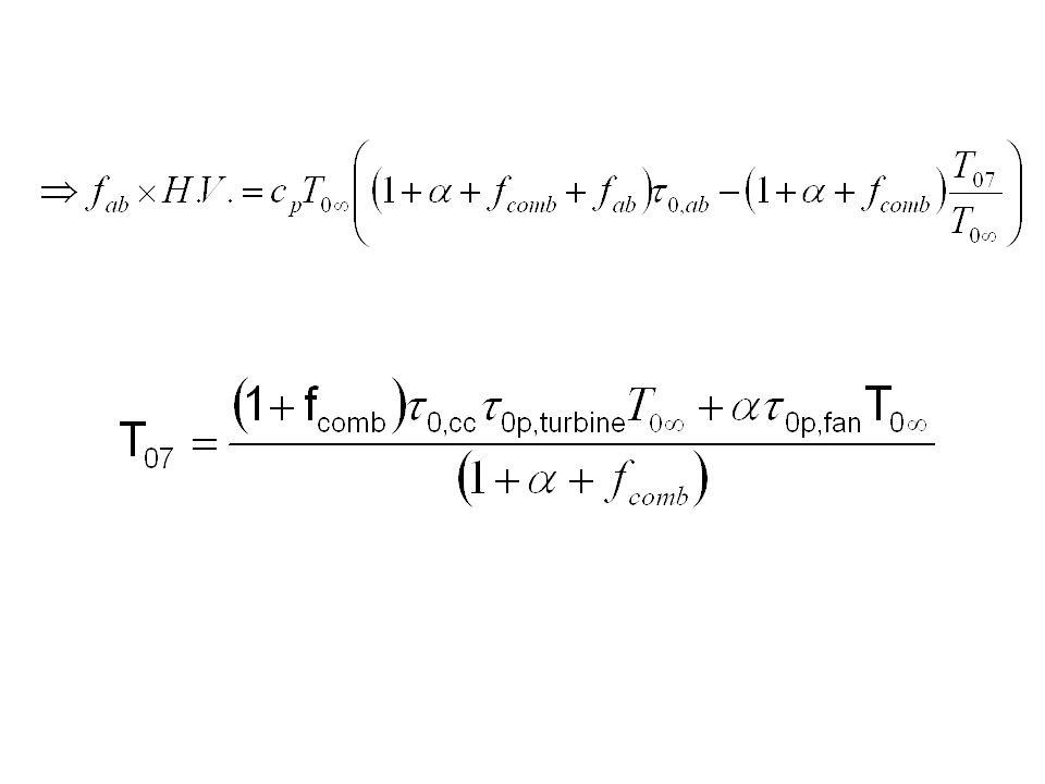
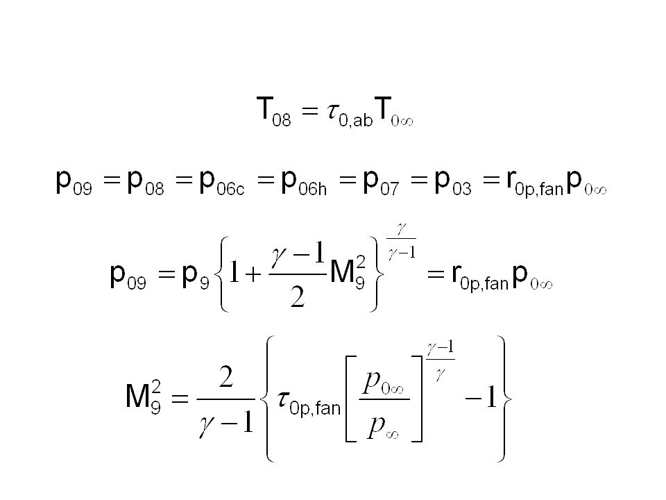
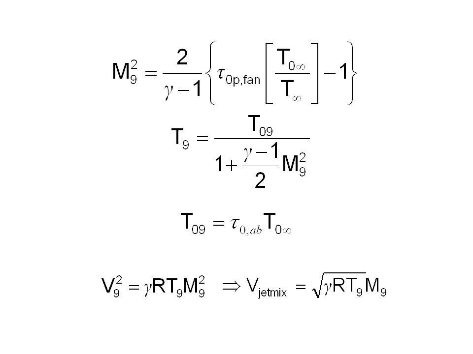
25
After burner temperatures are generally less than after combustor temperature.
T08 < T05 Generally the percentage of enhancement in thrust is specified to determine temperature of the gas after burner.

29
Generation of Thrust : The Capacity
Propulsive Power or Thrust Power: Specific Thrust based on total jet flow S,

30
TF30: Pratt and Whitney Mixed Flow Turbofan Engine
The TF30−P−414 engine is a mixed flow, dual spool afterburning low by pass turbofan designed and manufactured by Pratt and Whitney Aircraft of West Palm Beach, Florida. The engine incorporates a nine stage low pressure compressor including a three stage fan driven by a three stage low pressure turbine; and a 7 stage axial flow high pressure compressor driven by a single stage high pressure turbine.

31
SPECIFICATIONS:TF30 Bypass airflow ratio: 0.878 to 1
Development of TF30−P−414 was initiated in March 1969. TF30−P−414A was placed in service in October 1982. 929 TF30−P−414’s were converted to P−414A’s with conversion kits; conversion completed November 1987. 269 P−414A’s were purchased. Max Design Pressure Ratio, SLS :Fan: 2.14 to 1 Overall: 19.8 to 1 Bypass airflow ratio: to 1 Max rated airflow: lbs/s

32
F110-GE-400 Mixed Flow Turbofan Engine

33
Details of F110-GE 400 The F110−GE−400 engine is a mixed flow, dual spool afterburning low by pass turbofan designed and manufactured by General Electric Aircraft Engines in Lynn, Massachusetts. The engine is of modular construction, consisting of six engine modules, and an accessories gearbox. The engine incorporates a 3−stage fan driven by a two stage low pressure turbine; and a 9−stage axial flow high pressure compressor driven by a single stage high pressure turbine. To moderate engine performance at various power levels the engine features a variable geometry system. The combustor is a through flow annular type. The hinged flap cam linked exhaust nozzle is hydraulically actuated. The engine mounted accessory gearbox provides the necessary extracted power needed to drive the accessories. The engine control system regulates speeds, temperature levels and fuel flow for afterburning and non after burning operation. The lubrication and ignition system are self contained on the engine. Development was initiated April 1984 and engine was placed in service in late 1986

34
SPECIFICATIONS:F110-GE - 400
Max Design Pressure Ratio, SLS:Fan:3.2 to 1 Overall: 29.9 to 1 Airflow Capacity: Max rated airflow: lbs/s

Similar presentations