Download presentation
Presentation is loading. Please wait.

1
FNAL-SCRF 会議報告 1. Cryomodule, Plug-compatible Interface ( 大 内) 2. High Pressure Code, 5K Shield (Tom Peterson)
 2. High Pressure Code, 5K Shield (Tom Peterson)")
2
1 . Cryomodule, Plug-compatible Interface Discussion of specific table definition Presentations of Plug-compatibility issues for cryomodules – Plug compatibility and EDMS Don Mitchell – ILC and PrX cryomodules Sergei Nagaitsev – Interfaces XFEL power couplers Serge Prat – Radial wedge clamp flange seal Ed daly

3
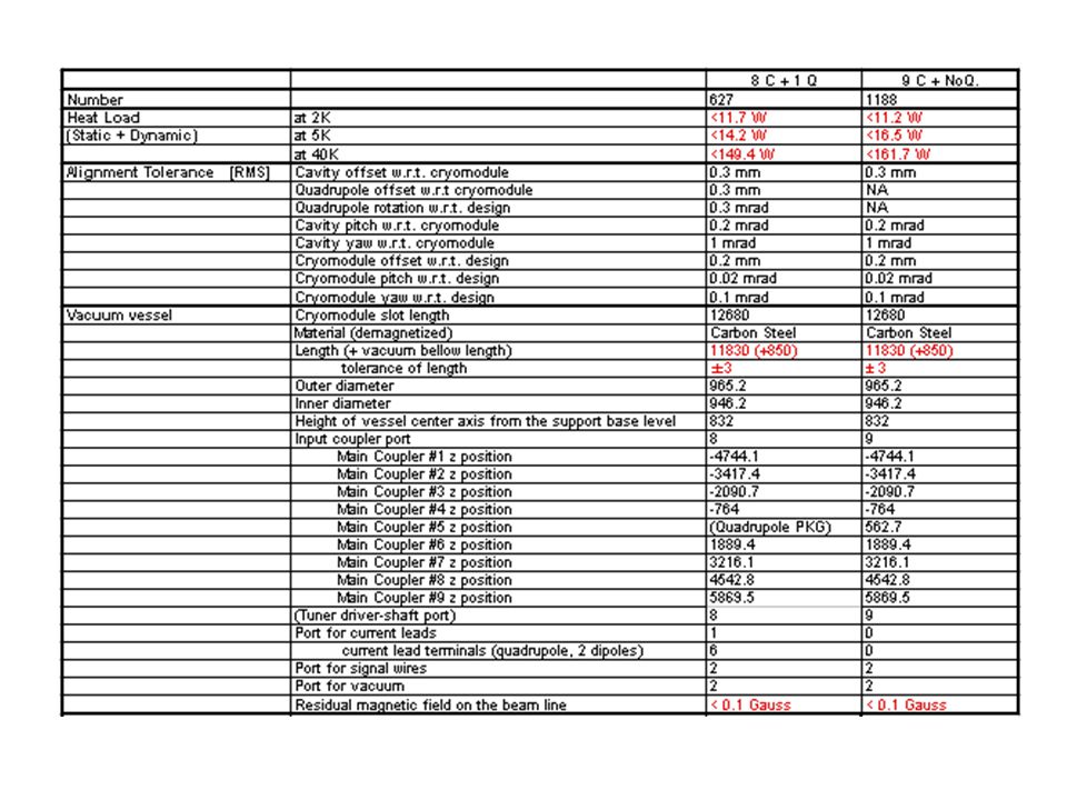
Specification Table for Cryomodule Items of specific parameters are discussed and almost decided. – Heat load – Alignment tolerance – Vacuum vessel dimensions and functions – Cavity helium jacket – Cooling pipes – Support posts, Thermal shields, Quadrupole package – Thermal constraint

5
From comments and discussions for spec. table The listed values are mainly referred to the T4CM design. – The numbers must be revised from the concept design study of the cryomodule. – The listed number should be considered for industrialization. Organize the group and the taskforce of Parameter Study of the ILC Cryomodule The machining tolerance and the alignment tolerance of the components in the module need to be decided with the process and cost for manufacture and assembly. Taskforce of Tolerance Study of the ILC cryomodule Company person should be included in this study.

6
Interface definition of the plug-compatible cryomodule Many types of sealing and flange + RW clamp flange seal(J-Lab) PM Akira Yamamoto will propose the taskforce of the connection flange system. The flange should be the interface of plug-compatibility.

7
ILC couplers: Define interface in terms of: material and geometry, heat load, surface finish, bolts and nuts, seals, which WP provides what if these interfaces are respected, then couplers: are plug-compatible but may be different (≠ vendors, ≠ batches) Big constraint on coupler structure (2 separate parts) due to module assembly principles: cold part assembled on cavity string in clean room warm part assembled on cryomodule outside clean room From Serge Prat presentation, The flange should be the interface of plug- compatibility. Cavity Package-2: Input Coupler

8
Tuner FNAL-T4CM Blade tuner STF-LL Coaxial ball screw tuner STF-BL Slide Jack tuner DESY-XFEL Sacley tuner Space envelope and location Interface items Cavity integration group

9
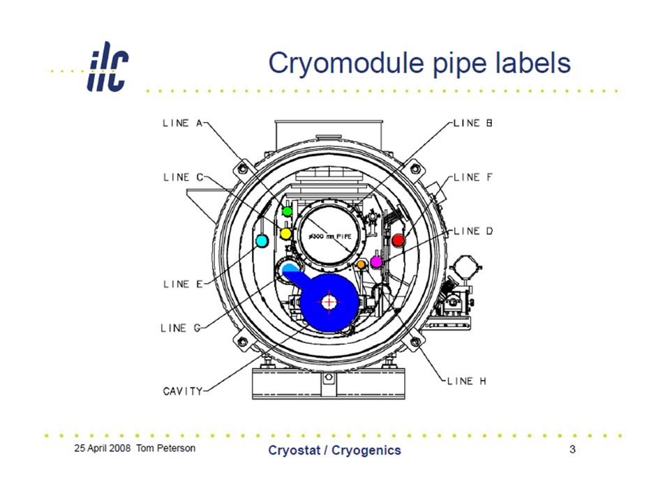
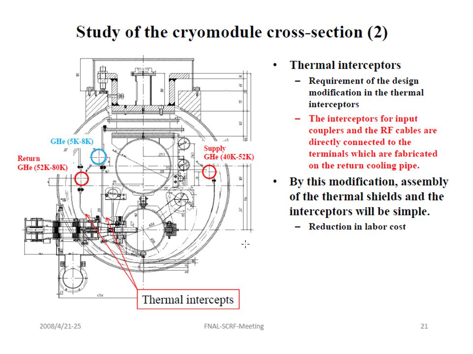
Cooling Pipes Cooling pipe size, position and material are decided for plug-compatibility of cryomodule. These parameters are listed in the specification table. Pipe location constraints 1.GRP, Cool-down and warm-up pipe, LHe supply pipe and Cavity Jacket (LHe level). 2.Shield cooling pipe (intercept location) Interface items
. 2.Shield cooling pipe (intercept location) Interface items.")
10
Vacuum vessel 1.Connection flange of vessel and vacuum bellow: T4-CM or DESY XFEL design 2.Main coupler flanges on the vessel: Locations defined in Spec. Table Need design study of the flange Interface

11
Input coupler and cavity jacket coordinate system incompatibility The direction of input coupler to cavity jacket – KEK-STF input couplers connect to beam pipes in the opposite direction with respect to the cavity package. DESY, FNAL style KEK-STF cavity package FNAL, DESY cavity packages

12
Conclusion (CM) 1.Specification – To finalize the items and values; Group and Taskforce of Parameter Study of the ILC Cryomodule Taskforce of Tolerance Study of the ILC cryomodule 2.Interface for plug-compatibility of cryomodule – Cavity package Beam pipe connection flange and input coupler-vacuum vessel flanges – Taskforce of cold flange sealing system should be proposed. Tuner space envelop and location (work with cavity package integration group) – Cooling pipe Pipe size and location (should be decided in the specification table) – Vacuum vessel Connection flange of vessel and vacuum bellow Input coupler flanges – Coordinate system definition Accelerator system and cryomodule
 – Cooling pipe Pipe size and location (should be decided in the specification table) – Vacuum vessel Connection flange of vessel and vacuum bellow Input coupler flanges – Coordinate system definition Accelerator system and cryomodule.")
13
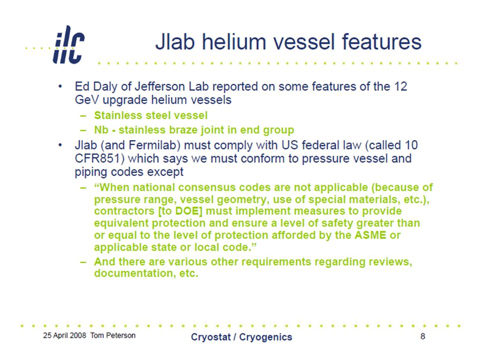
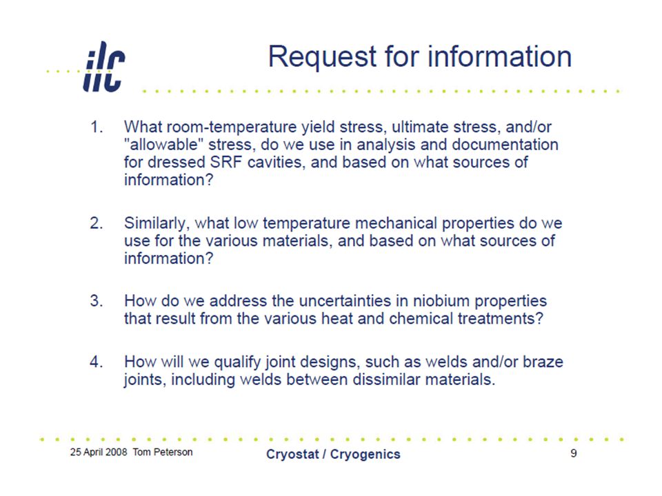
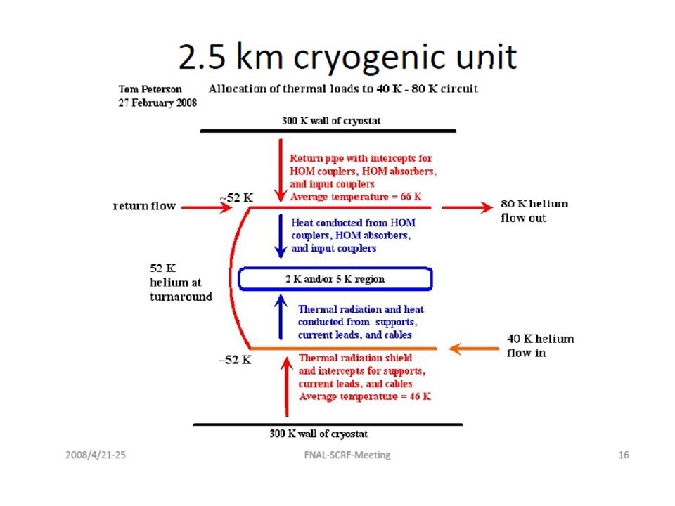
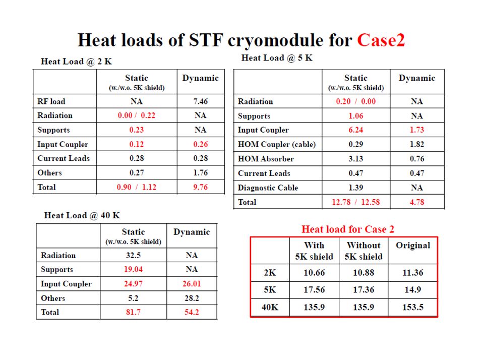
2. High Pressure Code, 5K Shield

19
(CM-WP.#2, #3)
")
Similar presentations


 H. Hayano Baseline Design based on the meeting discussion.>")


 Don Mitchell, 16 JAN 2006.>")

 STF-BL その他 空洞、シー ル Φ 78 mm ビームパイ プ、アルミヘキサゴ ン Φ 80 mm ビームパイ プ、インジウムヘリ コ LL, Re 入力カプ ラー TTF-III 円筒セラミック窓.>")

 2010' Feb. 05 STF Meeting for S1-G Global Design Effort 1 Preparation Status at KEK for S1-Global Eiji Kako (KEK, Japan)>")
