Download presentation
Presentation is loading. Please wait.

1
UMKC Senior SUBSTATION DESIGN TEAM
Website:

2
UMKC Senior Substation Design Team
Members: Zane Potts - Power Transformer Payam Ansari - Circuit Breakers Brandon Howland - Protective Relaying Robert Biggs - Lightning Mitigation Ehab Abdelhaq - Grounding Gary Kertz - Substation Layout Layout Website:

3
What is a substation used for ?
One of the main goals that every electrical utility company has is transportation of electrical energy from the generating station to the customer, while meeting the following main criteria: • High reliability of power supply • Low energy cost • High quality of energy (required voltage level, frequency etc.)
")
4
Power Transformer

6
Forms Core Shell

7
How It Interfaces

8
Disconnect Switches Bushings Current Transformer Circuit Breaker

9
Disconnect Switch and Circuit Breaker
Purpose of Circuit Breakers and Disconnect Switches Size of Breakers Fault Current Continuous Current X/R Ratio Power Flow

11
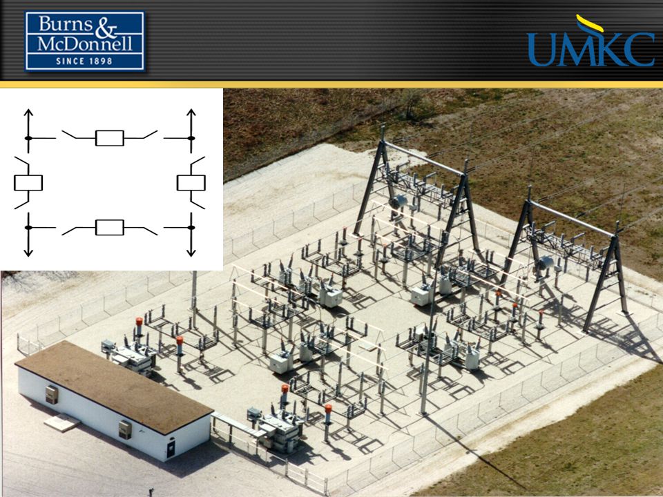
Our Team Design of Breakers
3-138KV Breakers Ring Layout 1-69KV Breaker

12
Protective Relaying

13
Protective Relaying

14
Zones of Protection

15
Lightning & Switching Surge Mitigation
Line Phasing

16
Coordination Lightning/Switching Surge Line Phasing Ehab – Grounding
Gary – Substation & Equipment Layout Line Phasing

17
Why grounding is important
Why grounding is important ? 1-Path for short circuit to remote earth 2-Provide safe step and touch potentials Grounding system design consists of all the following : Grounding rods Grounding grid Copper cables Equipment connectors

18
Main safety issues in grounding to be concerned about in designing the grounding system :
Step Voltage : Voltage difference in ground between your feet as you are standing or walking Touch Voltage : Voltage difference between equipment being touched and the ground at your feet

19
GPR ( Ground Potential Rise )
- V = I * R Fault current into the grounding system times resistance to “remote earth”

20
Grounding Design procedure :

21
Substation Layout Security and Serviceability Fencing Roadways
Lighting Foundation Stability Elevation Containment Controls Raceways Trench Conduit Controls house

22
Substation Layout Bus Layout Reliability Configuration Physical Layout
Cost Physical Layout Forces Potentials Materials used Copper Aluminum

23
Questions? Website: http://umkcsubstationdesign.weebly.com/
Professional Guidance Provided by: Website:

Similar presentations


 Loops Stacey Mighty Malcolm Distribution.>")


 Components New T& D Technologies This product.>")


