Download presentation
Presentation is loading. Please wait.

1
Introduction to Design for (Cost Effective) Assembly and Manufacturing
Note: The title slide name is intentionally “manipulated” to emphasize a couple of key points. The words “Cost Effective” have been highlighted in red and put in parentheses. This is there to emphasize that we only do this activity to make the overall “cost” of the assembly and part manufacturing lower. This includes costs associated with difficult assembly (thus taking more time/labor), quality defect costs (due to omitted, wrong or assembled wrong errors, etc.) and other costs associated with poor designs. The order of “Assembly” and “Manufacturing” was switched from the traditional order (the one that the standard “DFMA” acronym came from) in order to highlight that we actually want the belts to do DFA first and then do DFM. Material checklist: - copies of 1) PowerPoint handout and/or 2) Exercise handouts for all participants - DFA spreadsheet wall-chart (one for each team) for exercise - Instructor’s Notes (this packet) - Transparency set (backup to computer presentation) - Overhead Projector - Dry erase pens, several blank transparencies (if using overheads) - Gear Pumps: enough to provide 1 to each three-member group (or other hardware brought by students, can be different for each group) 3/16” hex wrench, shop towels, hammer & punch to assist with pump disassembly (or other appropriate hand tools) - PC with PowerPoint and color LCD projector
, quality defect costs (due to omitted, wrong or assembled wrong errors, etc.) and other costs associated with poor designs. The order of Assembly and Manufacturing was switched from the traditional order (the one that the standard DFMA acronym came from) in order to highlight that we actually want the belts to do DFA first and then do DFM. Material checklist: - copies of 1) PowerPoint handout and/or 2) Exercise handouts for all. participants. - DFA spreadsheet wall-chart (one for each team) for exercise. - Instructor’s Notes (this packet) - Transparency set (backup to computer presentation) - Overhead Projector. - Dry erase pens, several blank transparencies (if using overheads) - Gear Pumps: enough to provide 1 to each three-member group (or other hardware brought by students, can be different for each group) 3/16 hex wrench, shop towels, hammer & punch to assist with pump disassembly (or other appropriate hand tools) - PC with PowerPoint and color LCD projector.")
2
Purpose Statement To provide an overview of Design for Manufacturing and Assembly (DFMA) techniques, which are used to minimize product cost through design and process improvements. One of the “concerns” that people sometimes have about DFMA is their perception that changing the design is going to drive up costs. This slide is here to simply provide a second opportunity to emphasize that the process is intended to drive costs DOWN, and that the process should not make recommendations that increase the overall cost of the product (inclusive of assembly cost, quality cost, etc., not just referring to piece-part cost). 6
 techniques, which are used to minimize product cost through design and process improvements. One of the concerns that people sometimes have about DFMA is their perception that changing the design is going to drive up costs. This slide is here to simply provide a second opportunity to emphasize that the process is intended to drive costs DOWN, and that the process should not make recommendations that increase the overall cost of the product (inclusive of assembly cost, quality cost, etc., not just referring to piece-part cost). 6.")
3
Objectives Participants will understand:
Differences and Similarities between Design for Manufacturing and Design for Assembly Describe how product design has a primary influence Basic criteria for Part Minimization Quantitative analysis of a design’s efficiency Critique product designs for ease of assembly The importance of involving production engineers in DFMA analysis <Read Objectives to the class> “These are the basic skills that all of you should be able to walk out with today.” 7

4
Design for Assembly Definition: DFA is the method of design of the product for ease of assembly. ‘…Optimization of the part/system assembly’ The goal here is to enable the assembler to perform their job in the most productive manner possible, and reduce the amount of ‘work’ they must do to the simplest level. DFA is a tool used to assist the design teams in the design of products that will transition to productions at a minimum cost, focusing on the number of parts, handling and ease of assembly. 9

5
Design for Manufacturing
Definition: DFM is the method of design for ease of manufacturing of the collection of parts that will form the product after assembly. ‘Optimization of the manufacturing process…’ The goal is to make the manufacturing process as simple and efficient as the product’s functionality will allow. Design for Manufacturing is sometimes referred to as ‘Design for Manufacturability’ within industry DFA is a tool used to select the most cost effective material and process to be used in the production in the early stages of product design. 8

6
Differences Design for Assembly (DFA)
concerned only with reducing product assembly cost minimizes number of assembly operations individual parts tend to be more complex in design Design for Manufacturing (DFM) concerned with reducing overall part production cost minimizes complexity of manufacturing operations uses common datum features and primary axes These two methodologies should work in conjunction to simplify the work of machinists, assemblers, electricians, and engineers, or others at each stage in the life cycle of a product. They shouldn’t be viewed as competing, but rather compromises need to be made to balance all requirements. Some examples of DFM vs. DFA conflicts: 1. A one-piece plastic injection molding design reduces assembly by eliminating 6 parts. The molding, however, has so many intricate features that the tooling would be extremely expensive.<NOT MANUFACTURABLE> 2. A one-piece stamping is designed for an electronic circuit board housing. The sides of the housing, which were previously separate, now impede the assembler’s access to fastening locations. <CAN’T BE ASSEMBLED> 10
 concerned with reducing overall part production cost. minimizes complexity of manufacturing operations. uses common datum features and primary axes. These two methodologies should work in conjunction to simplify the work of machinists, assemblers, electricians, and engineers, or others at each stage in the life cycle of a product. They shouldn’t be viewed as competing, but rather compromises need to be made to balance all requirements. Some examples of DFM vs. DFA conflicts: 1. A one-piece plastic injection molding design reduces assembly by. eliminating 6 parts. The molding, however, has so many intricate. features that the tooling would be extremely expensive.<NOT. MANUFACTURABLE> 2. A one-piece stamping is designed for an electronic circuit. board housing. The sides of the housing, which were previously. separate, now impede the assembler’s access to fastening. locations. <CAN’T BE ASSEMBLED> 10.")
7
Similarities Both DFM and DFA seek to reduce material, overhead, and labor cost. They both shorten the product development cycle time. Both DFM and DFA seek to utilize standards to reduce cost Effective designs incorporate both philosophies, beginning with initial product development Organizations which bring the design teams together with the manufacturing teams will save much time and effort 11

8
Terminology Design for Manufacturing (DFM) and Design for Assembly (DFA) are now commonly referred to as a single methodology, Design for Manufacturing and Assembly (DFMA) . 12
 and Design for Assembly (DFA) are now commonly referred to as a single methodology, Design for Manufacturing and Assembly (DFMA)")
9
What Internal Organization has the most Influence over Price, Quality, & Cycle Time?
Design % Manufacturing % Talk about the design team that designed the classroom PC projector….whoever was on the team locked in at the design phase 60-80% of the cost. Cost of materials Number of parts used to achieve a particular function Types of parts Modularity Design Complexity…..these are all things we will talk about.

10
Knowledge and Learning
Marketing Knowledge DFSS Cost of Change Production Process Capability Knowledge High Low 100 90 80 70 60 50 40 30 20 10 100 90 80 70 60 50 40 30 20 10 Knowledge of Design Behavior Design Freedom to Make Changes Percentage What happens to our understanding of the behavior of our design over time? (increases). What happens to our ability to make changes over time? (decreases). If we do make changes, what effect does that have on the cost of the part? (increases) ….There is a BIG P….Production date that has to be met. Our objective is to increase the slope of the knowledge line so that we have more time to work out changes….better yet, we want to move this line over into the PPT area. There is a ‘chunk’ of manufacturing knowledge and information that can be shared once we go into production. Our objective then is to move this Manufacturing knowledge and information into the design phase along with Marketing information Time Into the Design Process
. What happens to our ability to make changes over time (decreases). If we do make changes, what effect does that have on the cost of the part (increases) ….There is a BIG P….Production date that has to be met. Our objective is to increase the slope of the knowledge line so that we have more time to work out changes….better yet, we want to move this line over into the PPT area. There is a ‘chunk’ of manufacturing knowledge and information that can be shared once we go into production. Our objective then is to move this Manufacturing knowledge and information into the design phase along with Marketing information. Time Into the Design Process.")
11
Design for Manufacturing
Sequence of Analysis Concept Design Optimize Design for Part Count and Assembly Design for Assembly Design for Manufacturing Question: What do we do first…..Design for Manufacturing or Design for Assembly? Answer: We do DFA first, then DFM. That way you’re not wasting your time optimizing the manufacturing processes on component parts that you might end up eliminating from the assembly. Optimize Design for Production Readiness Detailed Design

12
DFA is a process that REQUIRES involvement of Assembly Engineers
Design for Assembly DFA is a process that REQUIRES involvement of Assembly Engineers

13
Design for Assembly Principles
Minimize part count Design parts with self-locating features Design parts with self-fastening features Minimize reorientation of parts during assembly Design parts for retrieval, handling, & insertion Emphasize ‘Top-Down’ assemblies Standardize parts…minimum use of fasteners. Encourage modular design Design for a base part to locate other components Design for component symmetry for insertion Here are Key Principles which simplify and minimize assembly operations 29

14
Benchmark when possible
DFA Process Step 1 Product Information: functional requirements Functional analysis Identify parts that can be standardized Determine part count efficiencies Step 2 Determine your practical part count Step 3 Identify quality (mistake proofing) opportunities Step 4 Identify handling (grasp & orientation) opportunities Step 5 Identify insertion (locate & secure) opportunities Step 6 Identify opportunities to reduce secondary operations Step 7 Analyze data for new design Benchmark when possible
 opportunities. Step 4. Identify handling (grasp & orientation) opportunities. Step 5. Identify insertion (locate & secure) opportunities. Step 6. Identify opportunities to reduce secondary operations. Step 7. Analyze data for new design. Benchmark when possible.")
15
DFA Analysis Worksheet
Cummins Tools This is the Cummins DFA analysis worksheet. It is available to the students as an Excel file (and should have been distributed to them electronically for the class). They will use this tool during the exercises for this module.
. They will use this tool during the exercises for this module.")
16
Step One Product Information: functional requirements
Functional analysis Identify parts that can be standardized Determine part count efficiencies

17
Considerations/Assumptions
Step One The first part is essential (base part) Non-essential parts: Fasteners Spacers, washers, O-rings Connectors, leads Do not include liquids as parts (e.g.. glue, gasket sealant, lube)
 Non-essential parts: Fasteners. Spacers, washers, O-rings. Connectors, leads. Do not include liquids as parts (e.g.. glue, gasket sealant, lube)")
18
Part Identification List parts in the order of assembly
Assign/record part number If a process map of the assembly sequence is available, it should be used to define the order of assembly. If not, then start disassembling the parts and “invert” the order that you take things off! If Cummins part numbers are available, use them. If not, then simply use the “outline” form shown in the example to show parts and subassemblies.

19
So take it apart!

20
Count Parts & Interfaces
List number of parts (Np) List number of interfaces (Ni) Instruct the class to consider interfaces as the entire interaction of one part with another. If a part has several “bosses” or sections that all make contact with the same part (even if physically located separately from each other), this is one “part-to-part interface”.
 List number of interfaces (Ni) Instruct the class to consider interfaces as the entire interaction of one part with another. If a part has several bosses or sections that all make contact with the same part (even if physically located separately from each other), this is one part-to-part interface .")
27
Your Turn List parts in the order of assembly.
Assign part number to keep up with the part. List number of parts (Np) List number of interfaces (Ni)
 List number of interfaces (Ni)")
28
Determine Theoretical Min. No. of Parts
Current Design Consider Specification Other Options Does the part move relative to all other parts already assembled? Is the movement essential for the product to function? Must the part be separate to provide the required movement? Y Y Y Movement N Is the part of a different material, or isolated from, all other parts already assembled? Is a different material or isolation essential for the product to function? Must the part be separate to satisfy the different material or isolation requirement? Y Y Y Isolation N Is the part separate to allow for its in-service adjustment or replacement? Is the adjustment or replacement essential? Must the part be separate to enable the adjustment or replacement? Adjustment or Replacement Y Y Y N Non Essential Part Essential Part

29
Functional Analysis Current Design Consider Specification
Other Options Does the part move relative to all other parts already assembled? Is the part of a different material, or isolated from, all other parts already assembled? Is the part separate to allow for its in-service adjustment or replacement? Is the movement essential for the product to function? Is a different material or isolation essential for the product to function? Is the adjustment or replacement essential? Must the part be separate to provide the required movement? Must the part be separate to satisfy the different material or isolation requirement? Must the part be separate to enable the adjustment or replacement? Y Essential Part N Non Essential Part Movement Isolation Adjustment or Replacement Order of “Questions” going across column by column: Current Design - Consider the design only as is Consider Specs. - Consider as is and ask if it has to be Other Options - Should provoke ideas of how the design could be Order of “Questions” going down row by rows: Movement - Does it move and does it have to? Isolation - Is the part of a different material or isolated and is that necessary? Adjustment or Replacment - Does the servicing or replacement of the part require it to be separate? This should be a cross-functional activity!!! This helps make the ‘invisible, visible.

30
Determine if Parts Can be Standardized
Can the current parts be standardized?: Within the assembly station Within the full assembly Within the assembly plant Within the corporation Within the industry Should they be? (Only put a “Y” if both answers are yes…) This mostly applies to fasters, connectors, seals/gaskets, etc. though it can also apply to major subassemblies (like EGR valves).
 This mostly applies to fasters, connectors, seals/gaskets, etc. though it can also apply to major subassemblies (like EGR valves).")
31
Theoretical Part Count Efficiency
Theoretical Min. No. Parts Total Number of Parts Theoretical Part Count Efficiency Theoretical Part Count Efficiency = * 100 = * 100 The “Goal” arrow points to 10%, because that number of parts (10% of the current total) is the “entitlement” or “stretch goal” that this assembly could theoretically reach. The practical target is to redesign and achieve a system that has an efficiency score of 60% or higher. It is not typically worthwhile to push for 100% efficiency. = 10% Goal Rule of Thumb – Part Count Efficiency Goal > 60%
 is the entitlement or stretch goal that this assembly could theoretically reach. The practical target is to redesign and achieve a system that has an efficiency score of 60% or higher. It is not typically worthwhile to push for 100% efficiency. = 10% Goal. Rule of Thumb – Part Count Efficiency Goal > 60%")
32
DFA Complexity Factor – Definition
Cummins Inc. metric for assessing complexity of a product design Two Factors Np – Number of parts Ni – Number of part-to-part interfaces Multiply the two and take the square root of the total This is known as the DFA Complexity Factor S Np x S Ni

33
DFA Complexity Factor – Target
Part 3 Part 2 DCF = S Np x S Ni Part 1 DCFt = S Npt x S Nit Part 4 Part 5 DCFt = 5 x 8 = 6.32 Smaller is better (Minimize Np and Ni) Let Npt = Theoretical Minimum Number of parts from the Functional Analysis Npt = 5 Let Nit = Theoretical minimum number of part to part interfaces Nit = 2(Npt-1) Nit = 2(5-1) = 8
 Let Npt = Theoretical Minimum Number of parts. from the Functional Analysis. Npt = 5. Let Nit = Theoretical minimum number of part to part interfaces. Nit = 2(Npt-1) Nit = 2(5-1) = 8.")
34
Determine Relative Part Cost Levels
Subjective estimate only Low/Medium/High relative to other parts in the assembly and/or product line This part of the exercise is simply done to help highlight parts that would be beneficial to eliminate. This will be used in the next step when deciding on “Practical Minimum Part Count”.

35
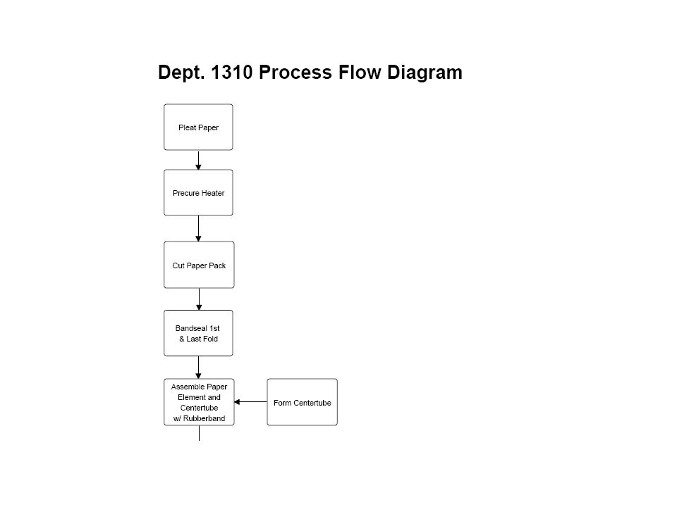
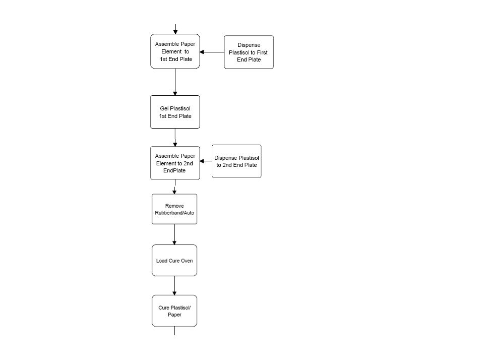
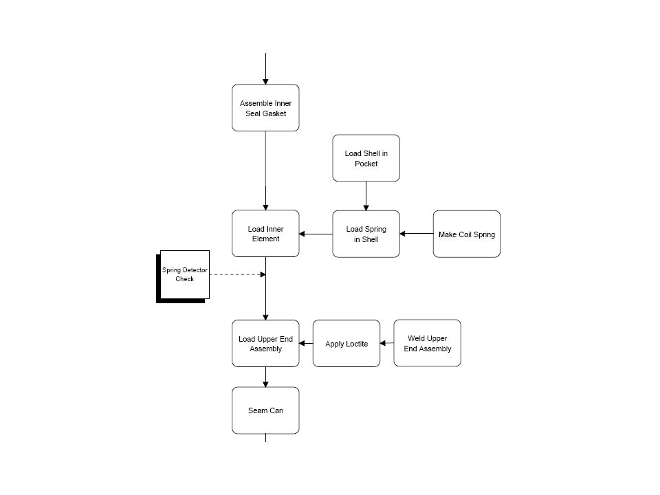
Cost Breakdown Media paper 21.4% Centertube 3.6% Endplates (2) 3.0%
Plastisol 2.6% Inner Seal 4.0% Spring % Shell % Nutplate % Retainer % Loctite % End Seal %

36
Step Two Determine Practical Minimum Part Count

37
Determine Practical Minimum Part Count
Team assessment of practical changes Tradeoffs between part cost and assembly cost This stage is dependent on the specific timing, resource and design control constraints that a given team is under. The team should make these decisions based on what they are recommending should be done within the scope of the work that they (or collaborating teams) can control. This is really about answering the question: “OK, so what are we actually going to try to do?”
 can control. This is really about answering the question: OK, so what are we actually going to try to do")
38
Creativity & Innovation
Theoretical Number of Parts... Theoretical Min. No. Parts ‘Blue Sky’ Innovation Practical Min. No. Parts Practical & Achievable Current Design Reality is somewhere in the middle! No. Parts

39
Cost of Assembly Vs Cost of Part Manufacture
Saving Total Saving Assembly Saving (DFA) Part Manufacture Saving (DFM) There is always a tradeoff between DFA and DFM. Taken to it’s extreme, DFA would recommend that you make one very complex part that requires no assembly. This can make that one part very difficult to manufacture. Taken to it’s extreme, DFM would recommend that you make parts that can be manufactured by knocking the big chunks off with sledgehammers and saying “close enough.” But this would make it really hard to put the parts together into an assembly that functions. The optimum is somewhere in between. Where the cost savings achieved by simplifying assembly are just balanced by the increased manufacturing costs of the more complex components. Optimum Part Count Reduction
 Part Manufacture Saving (DFM) There is always a tradeoff between DFA and DFM. Taken to it’s extreme, DFA would recommend that you make one very complex part that requires no assembly. This can make that one part very difficult to manufacture. Taken to it’s extreme, DFM would recommend that you make parts that can be manufactured by knocking the big chunks off with sledgehammers and saying close enough. But this would make it really hard to put the parts together into an assembly that functions. The optimum is somewhere in between. Where the cost savings achieved by simplifying assembly are just balanced by the increased manufacturing costs of the more complex components. Optimum. Part Count Reduction.")
40
Idea Classification Implementation Risk Long Term Medium Term
Step Two Implementation Long Term Medium Term Low Risk: These ideas can be implemented almost immediately The technology is not new to the product market Demonstrate that, with minimal testing and validation, the ideas can be incorporated Medium Risk: These ideas take a greater amount of research than low risk ideas Ideas may involve technology utilised by another industry May use a combination of unfamiliar materials and processes High Risk: These are ‘stretch’ or ‘blue-sky’ ideas Ideas require experimentation, research, testing and validation Ideas are on the edge of a new paradigm Ideas can thrust companies to the forefront of their field Ideas are almost always patentable Short/Medium/Long Term refers to the relative duration of time needed to complete the idea relative to the expected duration of the project. Short or medium term ideas can typically be implemented within the project duration and still allow time for adequate testing and integration within the overall design. Long term ideas are typically those that can only be completed toward the end of the project (or beyond) and may not allow adequate test/integration time. Short Term Low Medium High Risk
 and may not allow adequate test/integration time. Short Term. Low. Medium. High. Risk.")
41
Don’t constrain yourself to incremental improvement unless you have to!
This style doesn’t tear paper like the claw style and is much cheaper to produce!

42
Instructions Your Turn... Product Information: functional requirements
Steps One & Two Instructions Product Information: functional requirements Functional analysis Identify parts that can be standardized Determine part count efficiencies Determine your practical part count Great to have non-technical persons spread out onto each of the teams. There is no such thing as a bad idea! Sometimes the worst person on the team is a design engineer – they will often defend parts to the last! (Other times, of course, the designers are the most creative participants!) During this part of the exercise, go around and stress that they use the matrix questions to assess parts and actually restrict themselves to answering the questions to determine whether parts are essential or not. Remind them that the “practical” part comes at the end. They’re setting a “stretch goal”, so they need to be aggressive with it.
 During this part of the exercise, go around and stress that they use the matrix questions to assess parts and actually restrict themselves to answering the questions to determine whether parts are essential or not. Remind them that the practical part comes at the end. They’re setting a stretch goal , so they need to be aggressive with it.")
43
Fasteners Step One A study by Ford Motor Co. revealed that threaded fasteners were the most common cause of warranty repairs This finding is echoed in more recent survey of automotive mechanics, in which 80% reported finding loose or incorrect fasteners in cars they serviced

44
Component Elimination Example: Rollbar Redesign
‘..If more than 1/3 of the components in a product are fasteners, the assembly logic should be questioned.’ This rollbar assembly was greatly improved by combining parts and adding self-fastening features. Point out the “quote” at the top of the slide and then ask the class what percentage of components in a Cummins Engine are typically fasteners? 24 Parts 8 different parts multiple mfg. & assembly processes necessary 2 Parts 2 Manufacturing processes one assembly step 30

45
Fasteners: Cummins Engines
Recall: Rule of thumb - ‘..If more than 1/3 of the components in a product are fasteners, the assembly logic should be questioned.’ There is definitely room for improvement, but there will also be some fasteners that can not be eliminated. (It’s the nature of an engine that will be disassembled and repaired multiple times during it’s duty life that some joints/fasteners are required.) Data from Munroe & Associates October 2002
 Data from Munroe & Associates October")
46
Standard Bolt Sizes Minimize extra sizes to both reduce inventory and eliminate confusion during assembly The example shows all the fasteners used in a new engine design. The graph illustrates the length and diameter of the sizes. The goal is to minimize the number of sizes used and the stick to standard sizes. Illustration of one visual method of eliminating non-standard fasteners from a product. Replace infrequently used fasteners with common ones, especially for those which are very similar in size. Also point out that one of the pairs of both M10 and M11 capscrews only differ in length by .5 mm. Believe it or not, in at least one case, both of those capscrews were used in fastening the same component onto the engine and had to be done in the same station at the plant. This drove HUGE amounts of failsafing to ensure that the wrong capscrew did not get placed in the wrong hole on the part. ($200K +) There was no visual way that the operator could tell the difference (nor the material supply technician). Consequently, the potentials for quality issues were/are huge! How robust a design do we really have if a 0.5 mm variance in capscrew length and/or engagement means the success or failure of a joint? 38
 There was no visual way that the operator could tell the difference (nor the material supply technician). Consequently, the potentials for quality issues were/are huge! How robust a design do we really have if a 0.5 mm variance in capscrew length and/or engagement means the success or failure of a joint 38.")
47
Fastener Cost Select the most inexpensive fastening method required
screwing riveting plastic bending The time and tooling required progresses as the fasteners become more complex. snap fit 39

48
General Design Principles
Self-fastening features Here, 4 screws are eliminated, and the cover is now immediately secured to the base using snap-fit fasteners We haven’t perfected the snap-fit cylinder head yet, but we should be considering this possibility for covers, shields, etc. 34

49
General Design Principles
Symmetry eliminates reorientation The square part at left is not fully symmetric, since it is not identical in all four orientations (Exhibits 180 degree symmetry only). Asymmetric Part Symmetry of a part makes assembly easier 31
. Asymmetric Part. Symmetry of a part. makes assembly easier. 31.")
50
General Design Principles
Top-Down Assembly All assembly operations are done from above, which allows for maximum visibility and provides no obstructions to the operator. 35

51
General Design Principles
Modular Assemblies Imaging Drives Development Transfer/Stripping Cleaning Fusing Charge/Erase Copy Handling Electrical Distribution Photoreceptor Input/Output Devices What is the definition of modularity? (standardization of sub-systems….) All components can be removed as single pieces, which assists with servicing and troubleshooting. Can make the modules themselves expensive (and certainly more expensive than the one component that actually broke) but this is the trend in industry. Makes for faster repairs, less trouble-shooting time and quicker service events in general. Xerox photocopier 36
 All components can be removed as single pieces, which assists with servicing and troubleshooting. Can make the modules themselves expensive (and certainly more expensive than the one component that actually broke) but this is the trend in industry. Makes for faster repairs, less trouble-shooting time and quicker service events in general. Xerox photocopier. 36.")
52
Eliminated Parts are NEVER…
Designed Detailed Prototyped Produced Scrapped Tested Re-engineered Purchased Progressed Received Inspected Rejected Stocked Outdated Written-off Unreliable Recycled late from the supplier! Emphasize the impact on part count in a system…. Don’t just flash this slide and move on. It’s worth reading every bullet point. You’re trying to stress the number of things that go wrong with a part. I typically “speed” up as I get into the second column and then take a “big breath” and state the last one regarding “late from the supplier”…

53
Step Three Identify quality (mistake proofing) opportunities
 opportunities")
54
Mistake Proofing Issues
Cannot assemble wrong part Cannot omit part Cannot assemble part wrong way around. symmetrical parts asymmetrical parts

55
Mistake Proofing Issues
72 Wiring Harness Part Numbers CDC - Rocky Mount, NC This slide shows what the staging area for wiring harnesses at CDC looks like. They are like wrestling with an octopus, wires and connectors going every different direction. Having 72 different ones makes the chances of picking up the wrong one pretty high. (and you typically don’t discover it until further down the line where you have a wire that “won’t reach”). Main point: Reduce proliferation where possible and if you can’t, at least provide an easy way to identify the specific part (barcodes, highly visible part numbers, color-coding, etc.)
. Main point: Reduce proliferation where possible and if you can’t, at least provide an easy way to identify the specific part (barcodes, highly visible part numbers, color-coding, etc.)")
56
Step Four Identify handling (grasp & orientation) opportunities
 opportunities")
57
Quantitative criteria
Handling Time: based on assembly process and complexity of parts How many hands are required? Is any grasping assistance needed? What is the effect of part symmetry on assembly? Is the part easy to align/position? The Handling time for each part in the assembly must be determined. All of the above listed criteria affect the handling characteristics of a given operation. 47

58
Handling Difficulty Size Thickness Weight Fragility Flexibility
Slipperiness Stickiness Necessity for using 1) two hands, 2) optical magnification, or 3) mechanical assistance examples of parts which cause difficulty: Size: a small ball, such as a checkball Thickness: A very thin gasket Weight: A large steel block which requires two hands or a lifting mechanism Fragility: thin wooden sticks which break easily, require greater time Flexibility: Rubber band Slipperiness: an oiled or otherwise lubricated part Stickiness: heavily-greased part 48
 two hands, 2) optical magnification, or 3) mechanical assistance. examples of parts which cause difficulty: Size: a small ball, such as a checkball. Thickness: A very thin gasket. Weight: A large steel block which requires two hands or a lifting mechanism. Fragility: thin wooden sticks which break easily, require greater time. Flexibility: Rubber band. Slipperiness: an oiled or otherwise lubricated part. Stickiness: heavily-greased part. 48.")
59
Handling Difficulty size slipperiness sharpness flexibility
Each of these factors adds degrees of difficulty to the handling of parts. sharpness flexibility 49

60
Eliminate Tangling/Nesting
By ‘tying’ the ends of the spring together, they are prevented from becoming interlaced with on another. 40

61
Step Five Identify insertion (locate & secure) opportunities
 opportunities")
62
Quantitative criteria
Insertion time: based on difficulty required for each component insertion Is the part secured immediately upon insertion? Is it necessary to hold down part to maintain location? What type of fastening process is used? (mechanical, thermal, other?) Is the part easy to align/position? The Insertion time for each part in the assembly must be determined. All of the above listed criteria affect the insertion characteristics of a given operation. Both handling and insertion issues and their impact on assembly times can be “quantified” using the software “EASE” which is the Cummins Corporate Standard software used for Pre-determined Time Study analysis. 50
 Is the part easy to align/position The Insertion time for each part in the assembly must be determined. All of the above listed criteria affect the insertion characteristics of a given operation. Both handling and insertion issues and their impact on assembly times can be quantified using the software EASE which is the Cummins Corporate Standard software used for Pre-determined Time Study analysis. 50.")
63
Insertion Issues Provide self-aligning & self locating parts

64
Insertion Issues Ensure parts do not need to be held in position

65
Insertion Issues Parts are easy to insert.
Provide adequate access & visibility Tight clearances may lead to jams and hang-ups requiring the occasional use of a tool

66
Insertion Issues Provide adequate access and visibility
Tight clearances may lead to jams and hang-ups requiring the occasional use of a tool

67
Step Six Identify opportunities to reduce secondary operations

68
Eliminate Secondary Operations
Re-orientation (assemble in Z axis) Screwing, drilling, twisting, riveting, bending, crimping. Rivet
 Screwing, drilling, twisting, riveting, bending, crimping. Rivet.")
69
Eliminate Secondary Operations
Welding, soldering, gluing. Painting, lubricating, applying liquid or gas. Testing, measuring, adjusting. Eliminate painting of engines: Not feasible for all markets, but Daimler-Chrysler has been requesting it at CMEP as a cost reduction (they currently “clear-coat” the Ram engines at CMEP).
.")
70
Assembly Metrics Error = Sum all Y’s in Error Columns Proofing Theoretical Min. No. Parts Handling = Sum all Y’s in Handling Columns Index Theoretical Min. No. Parts Insertion = Sum all Y’s in Insertion Columns Index Theoretical Min. No. Parts 2nd Op. = Sum all Y’s in 2nd Op. Columns Index Theoretical Min. No. Parts

71
Set Target Values for These Measures
Analyze All Metrics First consider: Reduce part count & type Part Count Efficiency & DFA Complexity Factor Then think about: Error Proofing Error Index Then think about: Ease of handling Handling Index Ease of insertion Insertion Index Eliminate secondary ops. 2nd Op. Index Setting of target values is pretty subjective and really are just “goals” for the team. Ideally you would improve the design to where there were no more issues or “opportunities for improvement”. If you did that, then your assembly measures would have a “zero” in the numerator, so that would be your target! Set Target Values for These Measures

72
Instructions Your Turn...
Steps Two - Six Instructions Complete the remaining columns & calculate your product’s Assemblability Indices

73
Analyze data for new design
Step Seven Analyze data for new design

74
Benchmark when possible
DFA Process Step 1 Product Information: functional requirements Functional analysis Identify parts that can be standardized Determine part count efficiencies Step 2 Determine your practical part count Step 3 Identify quality (mistake proofing) opportunities Step 4 Identify handling (grasp & orientation) opportunities Step 5 Identify insertion (locate & secure) opportunities Review the steps (quickly) just to show that we covered them all. Step 6 Identify opportunities to reduce secondary operations Step 7 Analyze data for new design Benchmark when possible
 opportunities. Step 4. Identify handling (grasp & orientation) opportunities. Step 5. Identify insertion (locate & secure) opportunities. Review the steps (quickly) just to show that we covered them all. Step 6. Identify opportunities to reduce secondary operations. Step 7. Analyze data for new design. Benchmark when possible.")
75
In order of importance:
DFA Guidelines In order of importance: Reduce part count & types Ensure parts cannot be installed incorrectly Strive to eliminate adjustments Ensure parts self-align & self-locate Ensure adequate access & unrestricted vision Ensure parts are easily handled from bulk Minimize reorientation (assemble in Z axis) & secondary operations during assembly Make parts symmetrical or obviously asymmetrical This is the last slide for DFA - Next topic DFM
 & secondary operations during assembly. Make parts symmetrical or obviously asymmetrical. This is the last slide for DFA - Next topic DFM.")
76
Understanding Product Costs
Consideration of True Production costs and the Bill of Material Costs, Typical Costing Total Cost Pareto by Part Cost Pareto by Total Cost 1. Castings $$ 2. Forging $$ 3. ------ n. Fasteners c 1. Fasteners $$$$$ ------ n. Castings $$ Be aware of low cost parts that over the life cycle (or unit production cost) actually cost us more! Example shown is that castings (say oil cooler housings), while expensive, do not typically require a lot of additional tooling to handle, manage or further process. Capscrews, on the other hand, require extensive tooling (DC torque wrenches, calibration equipment, Calibration Laboratory personnel, etc.) to maintain our ability to use them. Bottom line: it’s not just the cost of the part, it’s the other costs that the part drives into the manufacturing/assembly process that matters.
 actually cost us more! Example shown is that castings (say oil cooler housings), while expensive, do not typically require a lot of additional tooling to handle, manage or further process. Capscrews, on the other hand, require extensive tooling (DC torque wrenches, calibration equipment, Calibration Laboratory personnel, etc.) to maintain our ability to use them. Bottom line: it’s not just the cost of the part, it’s the other costs that the part drives into the manufacturing/assembly process that matters.")
77
Selection of Manufacturing Method
Have we selected the Best Technology or Process to fabricate the parts? Is hard tooling Required... Have we selected the best Material needed for function and cost? Are we taking advantage of the technology in the process. Some features or processes may be free. An example is that a “spot-face” can often be added to a drilled hole on a casting with no additional cost, because by simply using a step drill, that feature can be added without requiring an extra movement of the machine tool. It requires a different cutter/bit to be placed in the spindle, but this is typically not a significant tooling cost increase. Have we looked at all the new Technology that is available

78
Selection of Manufacturing Method
Has the Design Addressed Automation Possibilities? Is the Product configured with access for and the parts shaped for the implementation of automation? HPI Injector line at the Fuel Systems plant in Columbus. Main point: If you’re going to ask a machine to pick a part up and/or position it, you have to give the machine a good consistently available and accessible place to hold onto. Robot grippers (and machine manipulators) are not as flexible and adaptive as human fingers! (at least yet…)
 are not as flexible and adaptive as human fingers! (at least yet…)")
79
Understanding Component Features
Part Features that are Critical To the Products Functional Quality Every Drawing Call Out is not Critical to Function and Quality Recommend that the students examine the “Classification of Characteristics” standard for more details.

80
Key DFMA Principles Minimize Part Count
Standardize Parts and Materials Create Modular Assemblies Design for Efficient Joining Minimize Reorientation of parts during Assembly and/or Machining Simplify and Reduce the number of Manufacturing Operations Specify ‘Acceptable’ surface Finishes for functionality Just a review/summary. This slide incorporates the main themes of both of the previous DFA and DFM summary slides. 68

81
References 1. Assembly Automation and Product Design
G. Boothroyd, Marcell Dekker, Inc 2. Product Design for Manufacture and Assembly G. Boothroyd and P. Dewhurst, Boothroyd Dewhurst, Inc. 1989 Marcell Dekker, Inc. 1994 3. Design and Analysis of Manufacturing Systems Prof. Rajan Suri University of Wisconsin 1995 4. Product Design for Assembly: The Methodology Applied G. Lewis and H. Connelly 5. Simultaneous Engineering Study of Phase II Injector Assembly line Giddings & Lewis 6. Design for Manufacturing Society of Manufacturing Engineers, (VIDEO) Just a few of the many references available on DFMA. 69
 Just a few of the many references available on DFMA. 69.")
Similar presentations


 due Thursday night (20 x 30) Meet at MOS at noon, or at D-Lab at 11:30 Channel 38 morning show??>")

>")