Download presentation
Presentation is loading. Please wait.

1
Mike Loptien Kirk Spowart Mike Gauthiere Chris Reid Vincent Wu

2
Read an RFID tag from 10 feet Implement WIFI capabilities GPS integration Use microcontroller

3
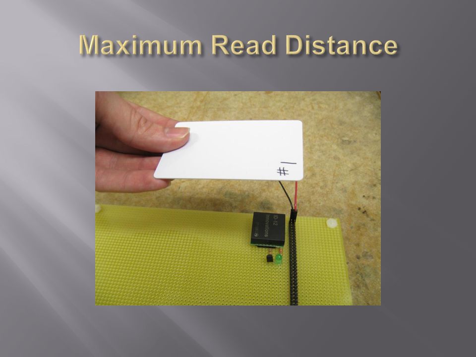
Current technology cannot read a passive tag from more than 5 inches Active tags are generally encrypted and very hard to use Active tags would require construction of our own antenna and reader hardware Wifi too difficult for this semester alone GPS too costly and not necessary for our project

4
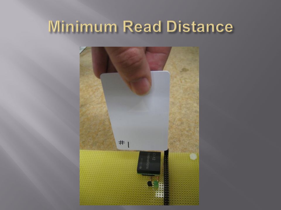
Read a passive tag from 3-4 inches Implement a touch screen and high-resolution display Store data on an SD card Audio output NIOS II on Cyclone II FPGA

5
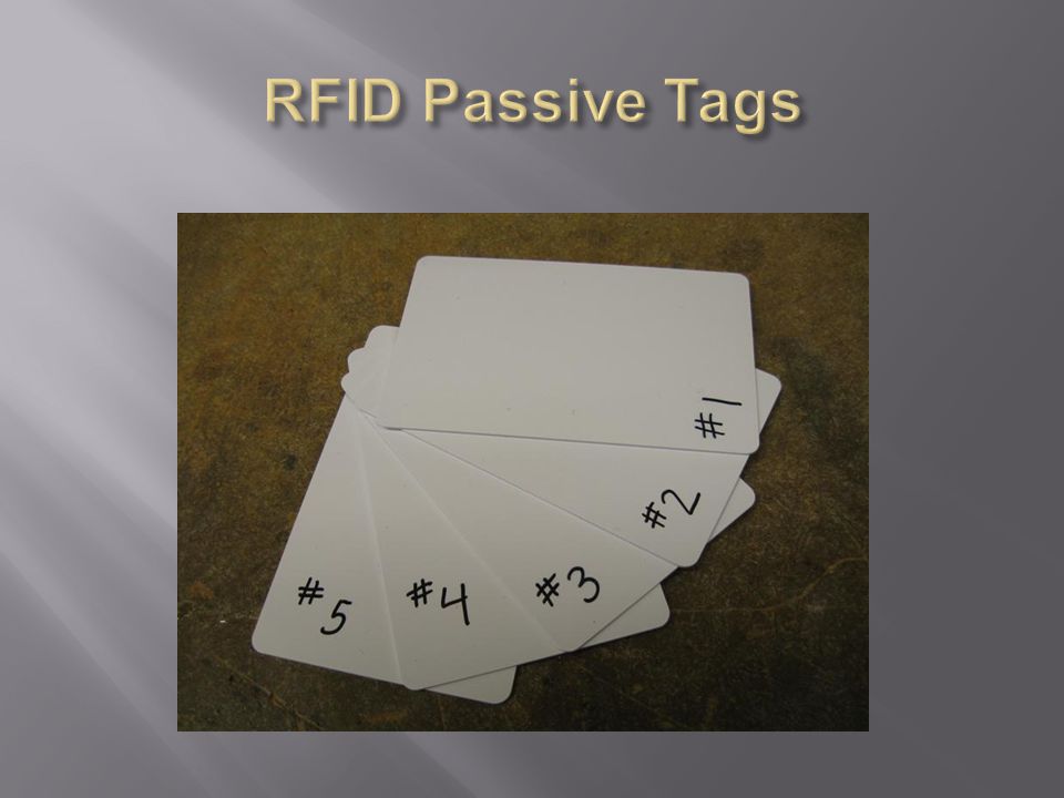
Grocery store: embed a passive tag in the price tags of items and store data about that item in the reader Retail stores: similar idea Museum: scan a tag near an exhibit to get info about it Basically a good way to tie information to a physical object

6
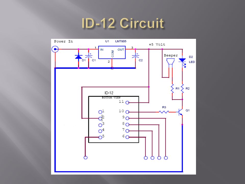
ID-12 Passive tag reader Max read range: 4” Simple Circuit and data reading

11
Collision detection is handled by the ID-12 It only outputs data when it correctly reads and decodes a tag

12
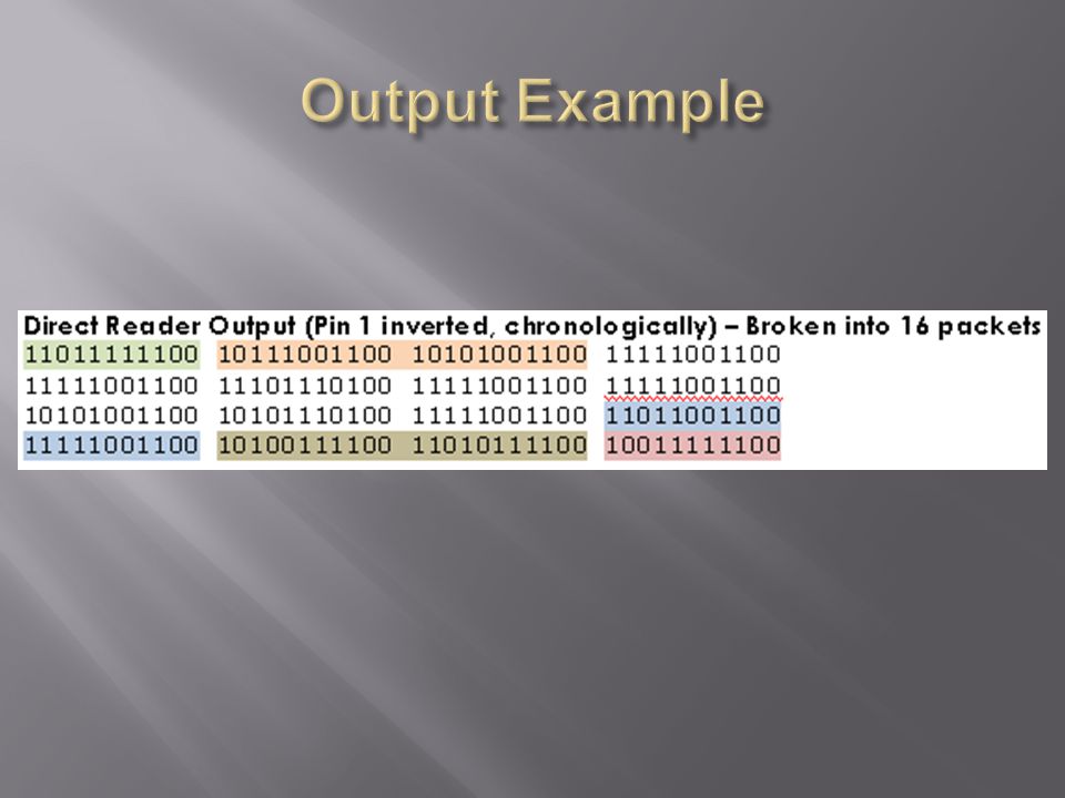
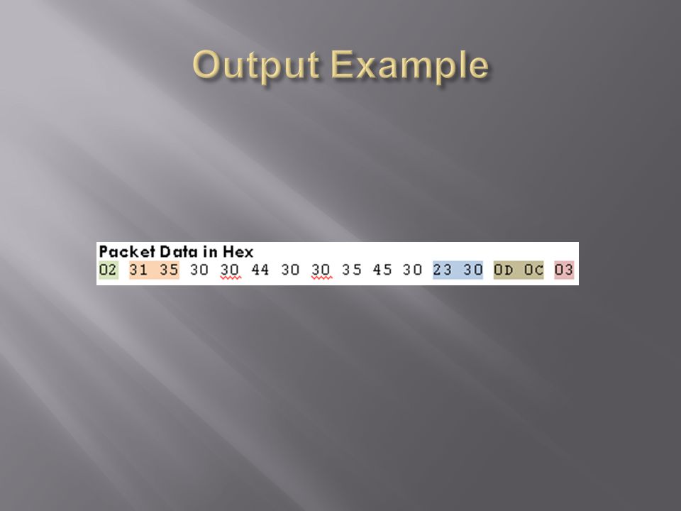
Output on D1, pin 8 LED Control on LED, pin 10 Format Select on +/-, pin 7 176 bits of output

13
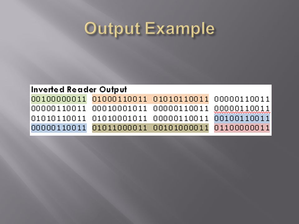
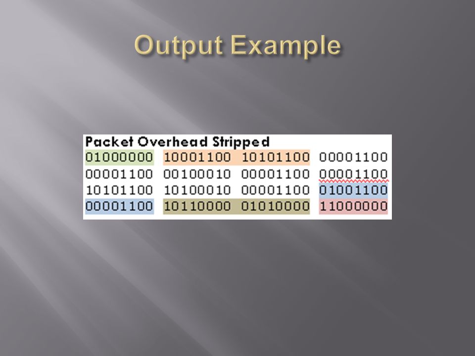
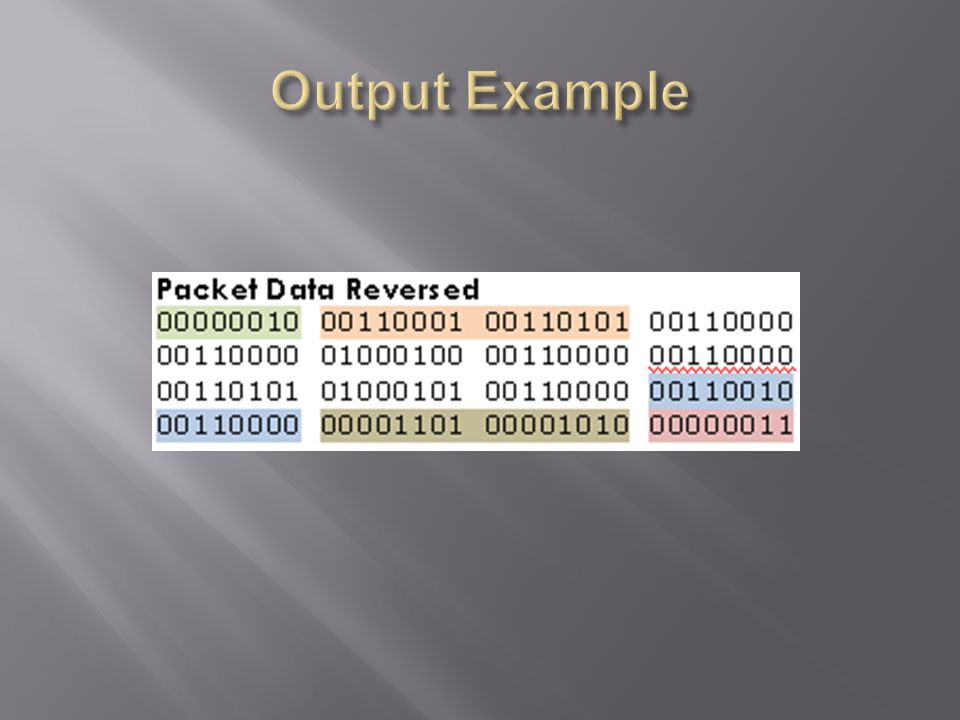
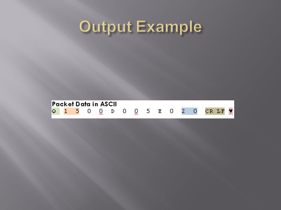
Output is inverted 176 bits at 9600 baud 16 serial packets, 1 start bit, 8 data bit, 2 stop bits and 0 parity bits Least significant bit first Transmits ASCII characters

20
Checksum XOR of all output packets

21
The Cyclone II

22
Up to 50MHz Will contain the NIOS II, SPI bus, Graphics controller, and RFID translation logic Cyclone II has good documentation, good supporting software, good expandability

23
Implemented on the Cyclone II FPGA Fully customizable processor Customizable onboard RAM C compatible through the Altera IDE

24
Used to control data input and output Video controller RFID input analyzer SD interface Programmed through USB blaster SPI bus, UARTs, Ram, Interrupt Priority, Custom Pin selection

27
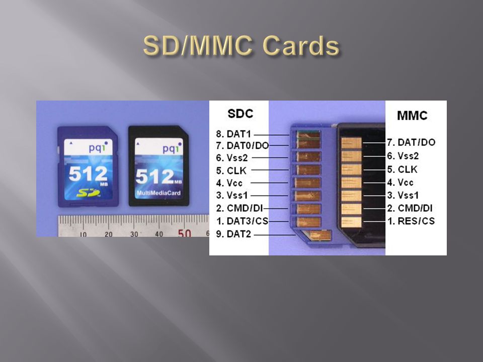
COM : Common - Connects to the housing WP : Write Protect Detect Switch CD : Card Detect Switch P9 : Not used in SPI mode (Pin 9 on SD Card) IRQ : Not used in SPI mode (Pin 8 on SD Card) DO : Serial Data Out GND : Ground - Connect this to COM to ground the housing CLK : Serial Clock VCC : 3.3V Power DI : Serial Data In CS : Chip Select
 IRQ : Not used in SPI mode (Pin 8 on SD Card) DO : Serial Data Out GND : Ground - Connect this to COM to ground the housing CLK : Serial Clock VCC : 3.3V Power DI : Serial Data In CS : Chip Select")
28
Standard Capacity SD Memory Card: Up to and including 2 GB High Voltage SD Memory Card – Operating voltage range: 2.7-3.6 V Default mode: Variable clock rate 0 - 25 MHz, up to 12.5 MB/sec interface speed (using 4 parallel data lines) Card removal during read operation will never harm the content Built-in write protection features (permanent and temporary) Card Detection (Insertion/Removal)
 Card removal during read operation will never harm the content Built-in write protection features (permanent and temporary) Card Detection (Insertion/Removal)")
29
Learn to communicate with SD/MMC on Altera Board Connect our own SD/MMC breakout board and communicate

30
Six-wire communication channel (clock, command, 4 data lines) Error-protected data transfer Single or Multiple block oriented data transfer
 Error-protected data transfer Single or Multiple block oriented data transfer")
31
When reading and writing to the SD card, the key problem is timing. The program must adhere to strict read/write timing to read and write data to/from the SD card. Read Timing Write Timing CodeDescription S Start bit (= 0) T Transmitter bit (Host = 1; Card = 0) P One-cycle pull-up (= 1) E End bit (= 1) Z High impedance state (-> = 1) CodeDescription D Data bits X Don’t care data bits (from SD card) * Repetition CRC Cyclic redundancy code bits (7 bits) Gray / WhiteCard Active / Host Active
 T Transmitter bit (Host = 1; Card = 0) P One-cycle pull-up (= 1) E End bit (= 1) Z High impedance state (-> = 1) CodeDescription D Data bits X Don’t care data bits (from SD card) * Repetition CRC Cyclic redundancy code bits (7 bits) Gray / WhiteCard Active / Host Active.")
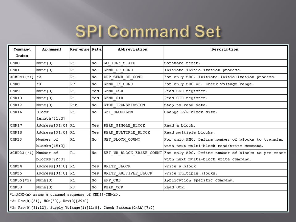
32
Command from host to card is fixed 6 bytes packet NCR-Command Time Response 0-8 bytes for SD DI signal must be kept high during read transfer When a command frame is transmitted to the card, a response to the command will be sent back to the host

34
One or more data blocks will be sent/received after command response Data block is transferred as a data packet that consist of Token, Data Block and CRC Stop Tran token means the end of multiple block write, it is used in single byte without data block and CRC

35
Single Block Read Multiple Block Read

36
Single Block Write Multiple Block Write

37
Sharp PSP Screen: 480x272 Resolution 24 bit color (8 for each R, G, B) CLK, Hsync, Vsync, DISP Control pins CLK = 9MHz Vsync = 17.1 KHz Hsync = 60 Hz Hantouch Touch Panel 4 wire analog resistive Requires A to D converter to determine location of touch
 CLK, Hsync, Vsync, DISP Control pins CLK = 9MHz Vsync = 17.1 KHz Hsync = 60 Hz Hantouch Touch Panel 4 wire analog resistive Requires A to D converter to determine location of touch")
38
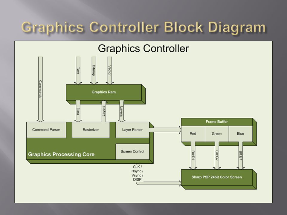
Goal: Accept commands from NIOS processor to create image and control output to the LCD screen Solution: Create a “Soft Graphics Controller” on the Cyclone II FPGA Command set Write text Write vector shapes Write bitmaps Manage image ‘layers’

39
Rasterizer Convert characters into bitmaps & write to layer Convert vector shapes into bitmaps & write to layer Write bitmaps to layer Layer Parser Determine layer order, size & position Write parsed layers to frame buffer Screen Control Logic Manage LCD control pins Clock dividers, etc. Layer Example

41
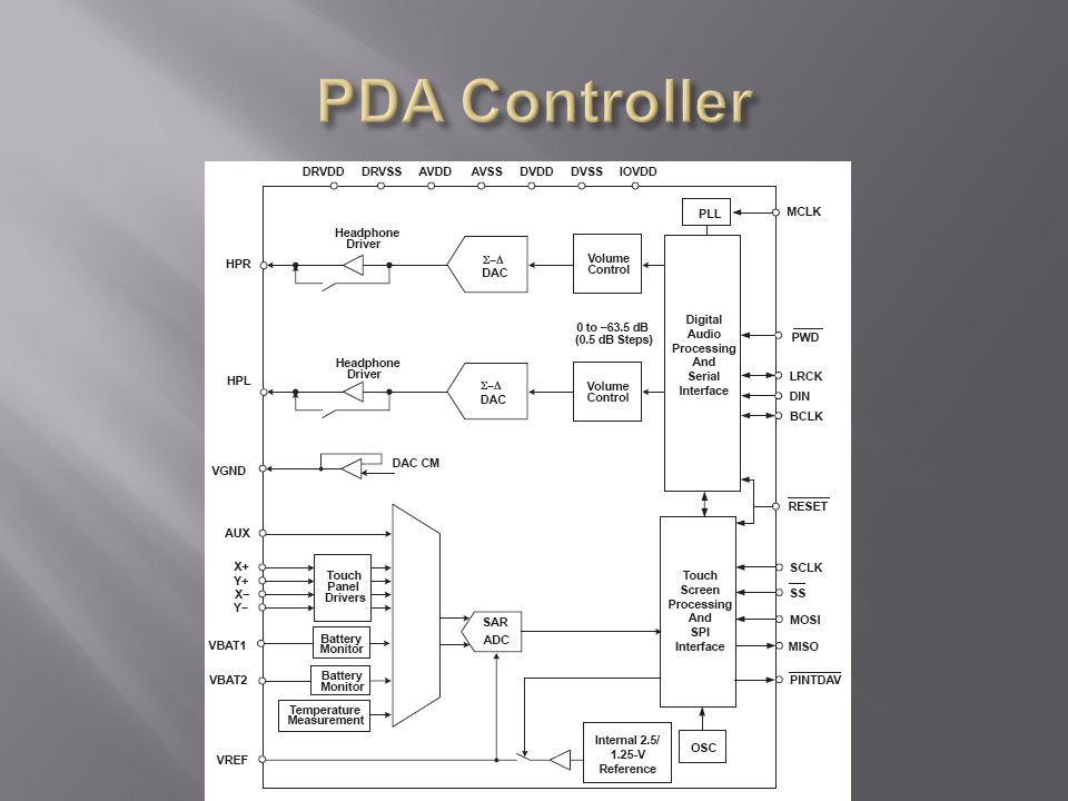
Texas Instruments TSC2102 PDA Controller Chip Configuration & communication via SPI A to D converter for touch panel A to D converter for battery voltage level measurement Stereo audio DAC & headphone amp Multiple audio codecs

44
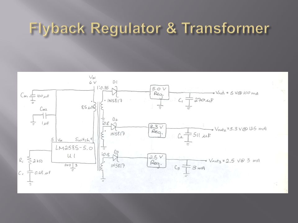
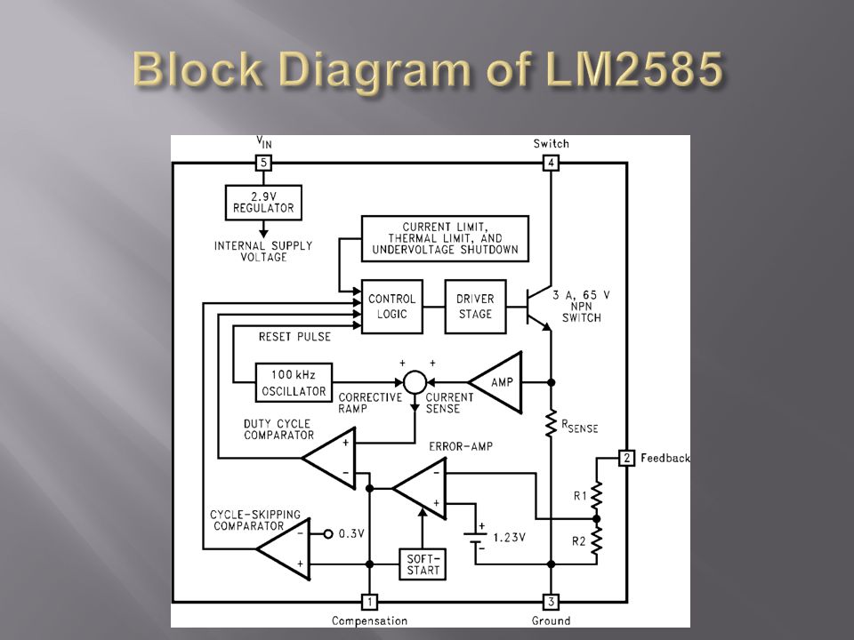
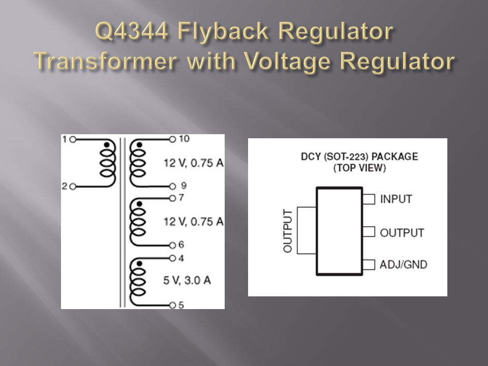
Two ways to design battery power system for RFID reader Main option is to use a flyback regulator and transformer with three secondary windings Alternate option is to use three linear voltage regulators

49
Pros: May use less power, parts may be less expensive, we would gain practical knowledge and experience Cons: More time would be required, voltage regulators still needed so flyback regulator and transformer may be superfluous, not a very big part of project so may not be worth several weeks of effort that can be spent on other parts of the project

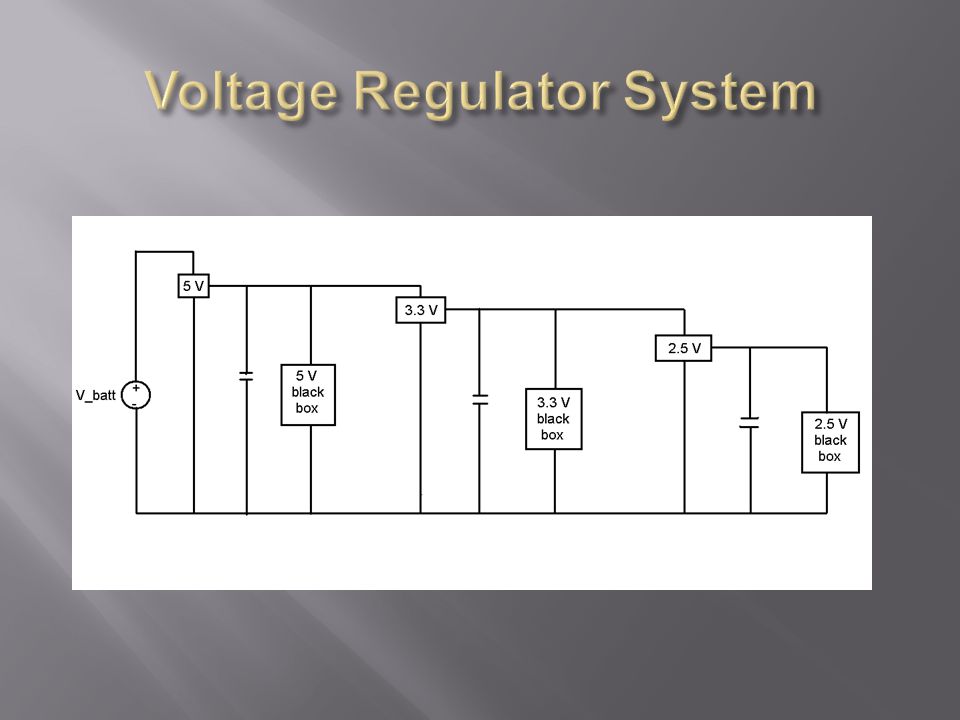
50
Pros: Much simpler to implement battery system, can handle the amount of juice we’ll need to power devices Cons: May consume more power

51
Example of Planned Battery Pack

52
6 V, 1400 mAH nickel metal hydride battery pack Two ways to build our battery pack Solder end to end Connect with the battery bars

55
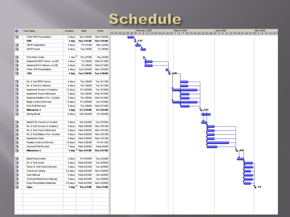
CDR: Order components, PCB design, board & processor familiarization, begin hardware modules Milestone 1: Finish RFID transceiver, memory, tag ID database Milestone 2: Finish touch screen interface, finish graphics controller, finalize control software Expo: Finish and test the final software, audio output, construct casing

56
Embedded systems & microprocessors: Mike L Mike G Power & batteries: Vince / Chris SD Card: Kirk Circuit construction: Chris / Vince Low level software: Kirk / Mike L High level software: Vince / Mike G / Chris

Similar presentations


 Derrick Culver Matt Zenthoefer.>")


