Download presentation
Presentation is loading. Please wait.

1
Chapter 19 Charging Systems

2
Charging Systems Primary purpose is to recharge battery
Changes mechanical energy into electrical energy Voltage is induced into a wire as it passes through a magnetic field The voltage has positive and negative pulses

3
AC Generator Construction
Rotor assembly Rotating magnetic field 4 .0 to 6.5 amps pass through coil One pole piece assumes north and the other south polarity

4
Alternating Current Charging Systems

5
Slip Rings and Brushes Regulated current supplied to rotor coil via slip rings and brushes

6
Stator Most AC generators use three stator windings

7
Stator (Cont.) Each stator conductor produces a single phase of AC current The phases are staggered 120° apart

8
End Frame Assembly Contains rotor shaft bearings and air ducts
Rectifier diodes attached to end frame Heat passes from diodes to air Cooling fans pull air through generator May have external or internal fans

9
Diodes with cooling fins
Rear driveshaft bearing

10
Liquid Cooled Generators
Water or coolant used to keep diode temperature down Eliminates fans and reduces noise Hoses connect generator to engine cooling system Allows for increased output and longer generator life

11
AC Generator Operation
Produce alternating current The AC must be converted, or rectified, into direct current, DC The AC passes through diodes

12
Diodes

13
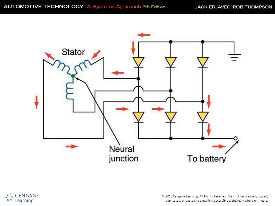
DC Rectification Using six diodes allows for full-wave rectification
Two diodes for each stator winding One diode is positive, the other negative The wye winding has a central neutral junction

15
Knowledge Check Describe how diodes are used to change AC into DC.
Diodes allow current to flow in one direction so by placing them with either a positive or a negative bias, the diodes can be used to block unwanted AC.

16
Factors Controlling Generator Output
Rotational speed of the rotor Number of windings in the rotor Current flow through rotor Number of windings in the stator

17
Voltage Regulation Output is controlled by varying current through the rotor Resistance in series with the field coil Sensing voltage allows the regulator to monitor system voltage Temperature also monitored

18
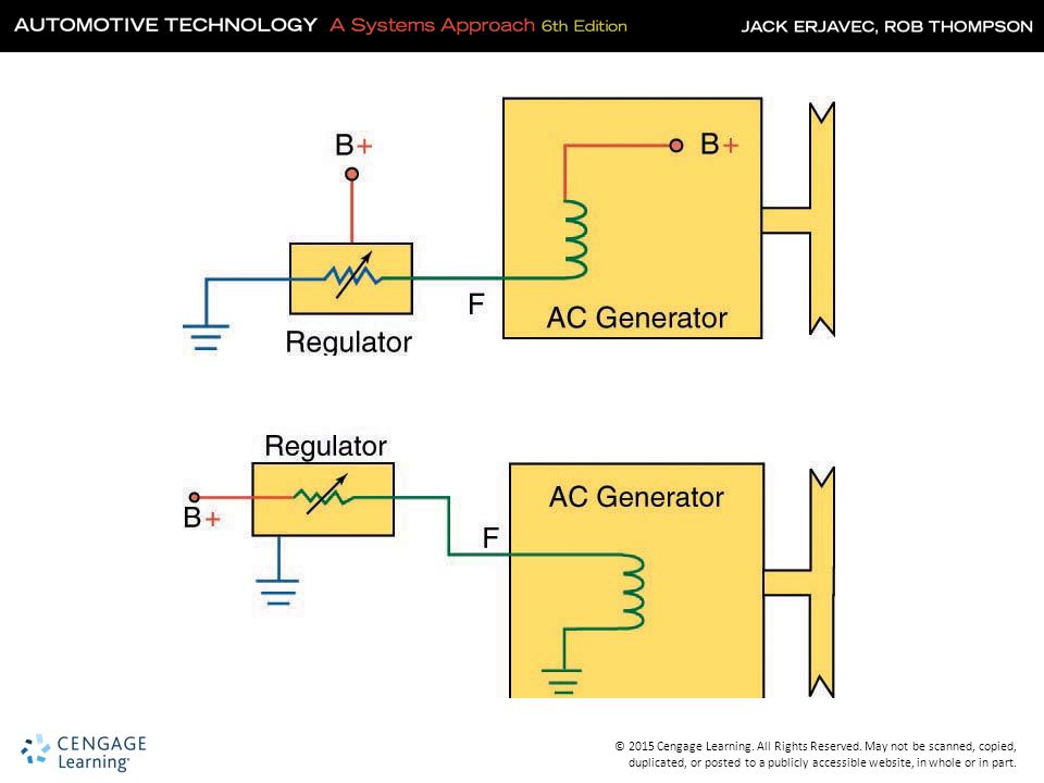
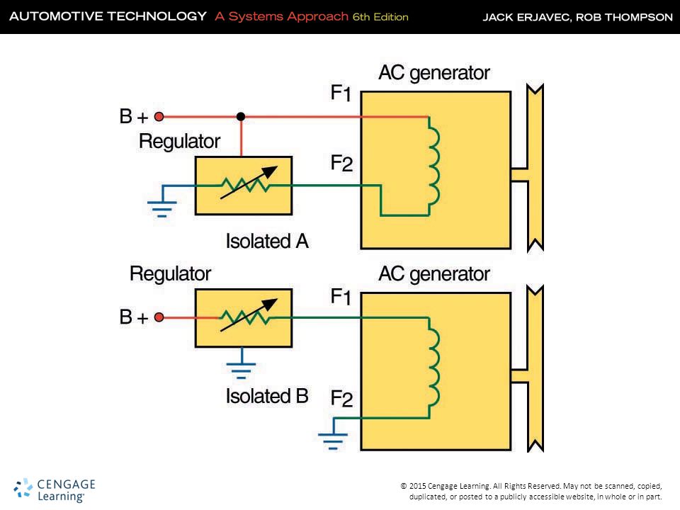
Types of Field Circuits
“A” type Has the regulator on the ground side of the field coil “B” type Has the regulator on the positive side of the field coil Isolated field The regulator can be on either the ground or the positive side

21
Types of Voltage Regulators
Electronic regulator Can be internally or externally mounted Uses a zener diode or pulse width modulation to control field current Integrated circuit voltage regulators Internally or externally mounted Controls field current through a diode trio

22
Types of Voltage Regulators (Cont.)
Computer-controlled regulation Is used on many late-model vehicles The computer (PCM) uses battery voltage and temperature to determine voltage needs Most systems use pulse width modulation to control field current
 uses battery voltage and temperature to determine voltage needs. Most systems use pulse width modulation to control field current.")
23
Pulse Width Modulation

24
Motor/Generators Using electronic controls, a generator can work as a motor Can be mounted external to the engine or mounted directly Capable of high charging outputs Can crank engine at high speeds

25
Motor/Generators (Cont.)
Capable of stop-start operation Regenerative braking Electrical assist

26
Regenerative Braking Braking energy used to recharge batteries
Motor/generator converts kinetic energy into electrical energy A combination of conventional and regenerative braking used Found on all hybrid vehicles

27
Regen

28
Knowledge Check Explain how the PCM controls generator output.
The PCM can pulse the voltage regulator very quickly on and off. This is called pulse-width modulation.

29
Preliminary Charging System Checks
Safety Precautions Disconnect negative terminal Avoid contact with generator output terminal Only apply pressure to front of generator housing when applying belt tension Observe correct polarity of battery cables Keep carbon pile tester off at all times Use caution around moving parts

30
Charging Indicators Indicator (charge) lamp Meters
Operates on the principle of opposing voltages Meters Voltmeter or ammeter display on dash Electronic voltage monitor Is used to monitor voltage and control a lamp or warning message

31
Charge Indicator Lamp

32
Inspection Inspect the battery Check wiring and connections
Inspect alternator mountings for loose or missing bolts Check condition of the drive belt Ensure proper pulley alignment

33
PCM-Controlled Systems
Check DTCs Monitor voltage with scan tool PCM monitors battery current, voltage, and temperature May adjust idle speed to increase charging rate

34
Battery Current Sensor

35
Noise Diagnosis Noise can be mechanical or electrical
Some electrical noise is normal Belts and bearings can produce noise Check mounting, wiring, cooling and A/C hoses and lines for misrouting Generator pulley should spin freely with belt removed

36
Regulator Tests Excessive charging most likely caused by voltage regulator Can also cause no output Some systems can bypass regulator for full-field tests Always follow manufacturer’s procedures

37
Voltage Regulator Test Point

38
Voltage Output Test Measure battery open circuit voltage
Run engine at fast idle (1500 rpm) No load voltage should be about 2 volts higher than open circuit voltage If low, increase speed to 2000 rpm and turn on accessories Voltage should be about 0.5 volts above open circuit voltage
 No load voltage should be about 2 volts higher than open circuit voltage. If low, increase speed to 2000 rpm and turn on accessories. Voltage should be about 0.5 volts above open circuit voltage.")
39
Current Output Test Run engine around 2500 rpm
Adjust carbon pile to maximum current output Should be within 10 amps of rated output

40
AC Leakage Test Connect DMM in series to charging output terminal with engine off Reading should be no more than 0.5 mA

41
Oscilloscope Checks

42
Knowledge Check A generator rated for 120 amp only produces 75 amps. Technician A says the voltage regulator may be faulty. Technician B says the diodes may be faulty. Who is correct? Both Technician A and B

43
Circuit and Ground Resistance
Check voltage drop of charging output connection and ground circuit. Test between battery positive and generator output terminal. Test between battery negative and generator case. Test under at least 20 amps output.

44
Voltage Drop Tests

45
Replacing a Generator Disconnect the battery negative connection.
Remove generator wiring and drive belt. Remove the generator. Compare new and old generator. Install and torque fasteners. Test the new generator.

Similar presentations


>")

 8 CHAPTER.>")


