Download presentation
Presentation is loading. Please wait.

1
Wind Energy System By: Andy Brown, Basheer Qattum & Ali Gokal Advisors: Dr. Na & Dr. Huggins

2
Outline Introduction Hardware Software Results Future Steps

3
History of Wind Energy Utilization

4
ADVANTAGES OF WIND POWER Wind is free and with modern technology it can be captured efficiently Wind does not cause green house gases or other pollutants Although wind turbines can be very tall each takes up only a small plot of land Excellent source for remote areas not connected to a grid Wind turbines have a role to play in both the developed and third world Available in a range of sizes meaning a vast range of people and businesses can use them Environmentally Friendly Economically Competitive

5
Goals Output maximum power despite fluctuating wind conditions. Utilize power electronics to perform conversions Successfully implement a DSP board to have a greater degree of control over our system to harness optimal energy To create a system that is applicable with real world industry

6
Functional Requirements (Hardware) Shall be able to produce.75 kilowatt but not more then 5 kilowatts Shall be able to convert wind power to single phase AC power Must be able to maximize wind power conversion
 Shall be able to produce.75 kilowatt but not more then 5 kilowatts Shall be able to convert wind power to single phase AC power Must be able to maximize wind power conversion")
7
Wind-Electric Systems Induction Generators, Directly Connected to the Grid Doubly-Fed, Wound Rotor Induction Generators Power Electronics Connected Generator

8
Top Level Diagram

9
Functional Description Sub Systems Generator Diode Rectifier Boost Converters Inverter

10
Brushless DC Motor Due to complications with size and Lab requirements, PMSG still. Max Current5.4 A Max Speed3600RPM Max Voltage 160 V Max Power 750W

11
Brushless DC Motor FrequencyRPM3-phase-to-neutral 51502.4 2060019.5 40120040.5 60180061 80240082 100300087 1203600104 ɳ =(120*f)/(poles)
/(poles)")
12
Brushless DC Motor

13
Three-Phase Diode Rectifier Max Peak Voltage1600V Max Peak Current 300A Max Current25A Max Voltage600V Output of DC generator after 3phase diode rectifier w/1.5mF Cap V = I*R Vo=(1.35Vin – V Diode ) P = I*V ɳ =(120*f)/(poles) Value of capacitor to ensure clear signal C=(Vp/2*f*Vr) =534μF Therefore we used 1.5mF
 P = I*V ɳ =(120*f)/(poles) Value of capacitor to ensure clear signal C=(Vp/2*f*Vr) =534μF Therefore we used 1.5mF")
14
Three-Phase Diode Rectifier V INRMS VOUT SIMULATION VOUT THEORICIAL PERCENT ERROR 1014.113.54.44 2028.5275.56 4056.5544.63 6084.5874.2 801131084.07 120169.51624.63 Vin = 64.0 V Vo = 84.0 V Io = 961 mA Speed = 3000 RPM R = 88Ω P = 80.72W

15
Three-Phase Diode Rectifier Output of DC generator after 3phase diode rectifier w/o Cap Vo = 85.0 V Io = 964 mA Speed = 3000 RPM Current DC Voltage

16
Three-Phase Diode Rectifier Output of DC generator after 3phase diode rectifier w/1.5mF Cap Vin = 64.0 V Vo = 84.0 V Io = 961 mA Speed = 3000 RPM DC Voltage 3φ Voltage

17
Interleaved Boost Converter

19
Boost Converter V InputDuty-CycleFreqVout-expVout-actual 520%300006.257.5 540%300008.339.01 560%3000012.5 580%3000025.024.25 Vo=Vin/(1-D), or for more accurate values, Vo= {[(V In -V IGBT* D)/(1-D)] – V Diode } IGBT: Switching Freq up to 300kHz Max voltage at 600V Max current at 60A
![Boost Converter V InputDuty-CycleFreqVout-expVout-actual 520% % % % Vo=Vin/(1-D), or for more accurate values, Vo= {[(V In -V IGBT* D)/(1-D)] – V Diode } IGBT: Switching Freq up to 300kHz Max voltage at 600V Max current at 60A](http://images.slideplayer.com/19/5769457/slides/slide_19.jpg "Boost Converter V InputDuty-CycleFreqVout-expVout-actual 520% % % % Vo=Vin/(1-D), or for more accurate values, Vo= {[(V In -V IGBT* D)/(1-D)] – V Diode } IGBT: Switching Freq up to 300kHz Max voltage at 600V Max current at 60A")
20
Boost Converter

22
Most time consuming part of Boost converter Gate Driver

23
Gate to emitter (pulse) ±30V Gate to emitter (cont) ±20V Max Gate Current ±250uA Gate driver output+18V 120/14 V AC-RMS 17.89V DC Output up too 600V Current up to 2A Shutdown mode for protection
 ±30V Gate to emitter (cont) ±20V Max Gate Current ±250uA Gate driver output+18V 120/14 V AC-RMS 17.89V DC Output up too 600V Current up to 2A Shutdown mode for protection")
24
Gate Driver

25
Software

26
Functional Description

27
DSP Board - TI TMS320F2812 PWM Generation 16-Bit 16 PWM outputs 0 V – 3.3 V ADC 12-Bit Analog Input: 0 V - 3 V

28
Controller Implementation Process SIMULINK CODE COMPOSER DSP

29
Testing Circuit Single Channel Boost Converter

30
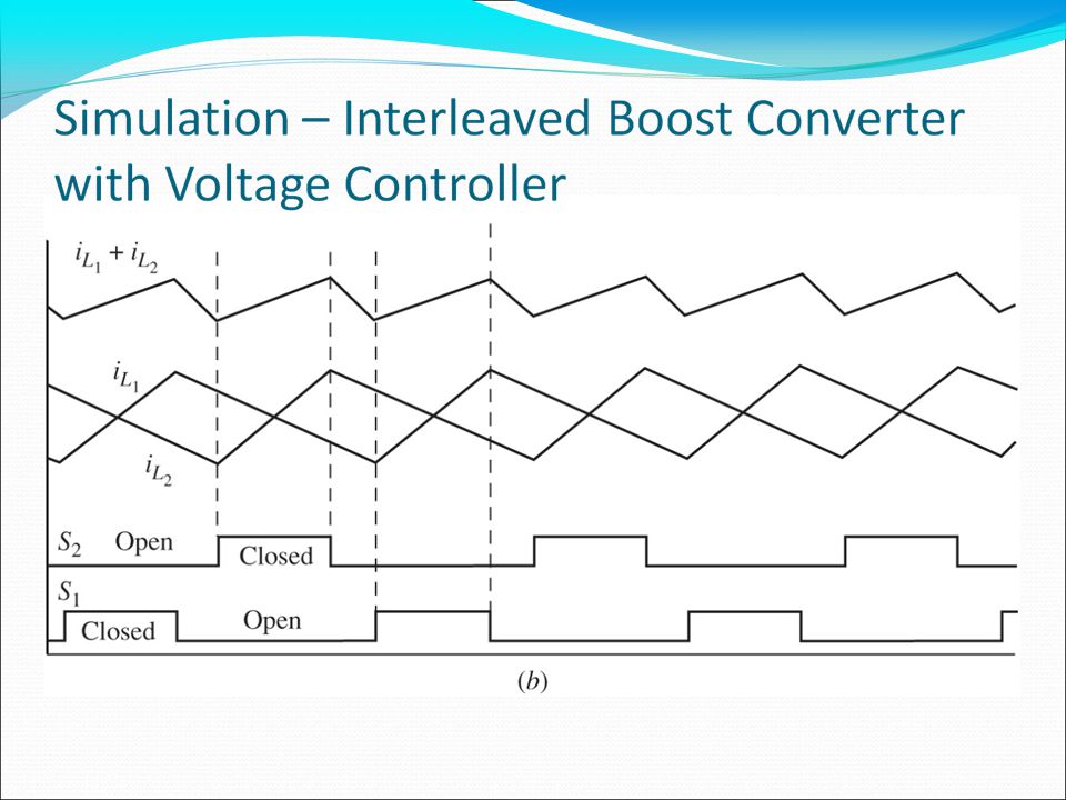
Simulation Open-Loop Controller

31
Testing Circuit Open Loop Controller

32
Testing Hardware Output Results

33
Testing Hardware Output Duty Cycle: 20% Input Voltage: 5.00 V Output Voltage: 6.00 V

34
Voltage Controller Simulation

35
Voltage Controller

36
Voltage Controller Output

37
Voltage-Current Controller Simulation

38
Voltage-Current Controller

39
Boost Converter Controller VS. Interleaved Boost Controller

40
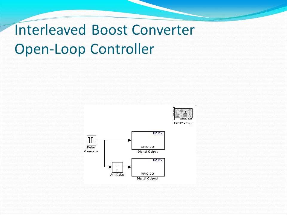
Interleaved Boost Converter Open-Loop Controller

42
Interleaved Boost Converter Open-Loop Controller Output

43
Single Phase Inverter Controller Sinusoidal Pulse Width Modulation

44
Unipolar PWM Vout = VdWhen T1,T4 is ON Vout=-VdWhen T2,T3 is ON Vout=0When T1,T3 or T2,T4 is ON

45
Unipolar PWM

46
LC Filter Magnitude Bode Plot for Second-Order LC Filter

47
LC Filter Chose L =.125mH Yields C = 240uF

48
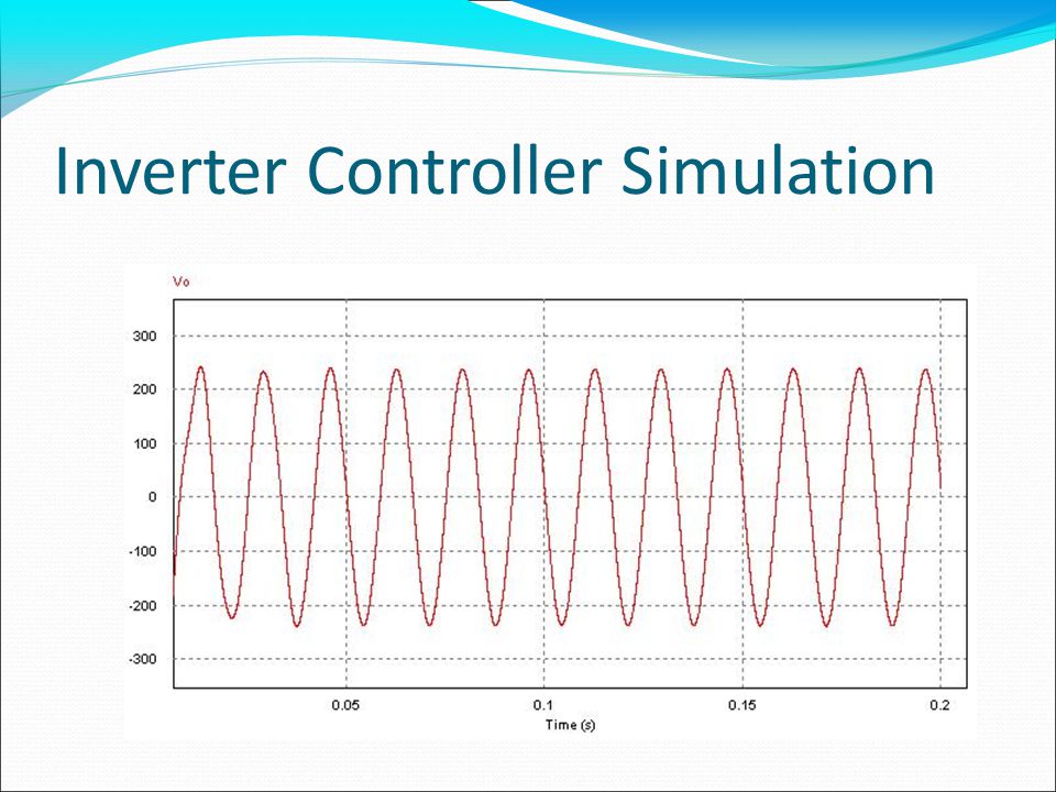
Inverter Controller Simulation

50
Interver Unipolar PWM Controller

51
Inverter SPWM - Output

52
Future Work - Controller Closed-Loop Voltage and Current Controller for Two- Channel Interleaved Boost Converter Maximum Power Point Tracking Controller Single-Phase Inverter Controller with Unity Power Factor Correction

53
Interleaved Boost Converter Voltage-Current Controller Same Controller as designed Need to output two PWM signal The second PWM signal has to been delayed by half the period

54
Interleaved Boost Converter Simulation

55
Maximum Power Point Tracking (MPPT)
")
56
MPPT Perturbation and Observation Method (P&O) MPPT algorithm adjusts duty cycle to achieve
 MPPT algorithm adjusts duty cycle to achieve")
57
MPPT – System Diagram

58
MPPT - Flowchart

59
MPPT Current Controller Design

60
Single-Phase Inverter Controller with Unity Power Factor Correction System Diagram

Similar presentations


>")


