Download presentation
Presentation is loading. Please wait.

2
Hand tools are tools manipulated and operated by our hands without the use of electrical energy Hand Tools and Their Uses Screw Drivers Screw drivers are made out of tools steel hardened and tempered at the tip. They come in various size and shapes, which are used to turn or drive screws with slotted heads

3
1.Standard Screwdriver. Standard screwdrivers are used to tighten or loosen flathead screws 2.Philips screwdriver. Philips screwdrivers are used to tighten or loosen Philip screws. 3.Stubby/close quarter screw driver. The lip is similarly shaped like the standard screw driver but with short shank blade and shorter handle which is made of plastic. 4.Offset Screwdriver. Offset screwdrivers provide means of reaching difficult flathead screws.

4
Pliers Pliers are used for cutting and twisting wires and to grip small parts. Pliers are available with both insulated and uninsulated handles. insulated handle pliers should be used when working on or hot conductors

5
1.Slip Joint Pliers Are used for a wide range of service involving gripping, turning and bending. 2.Side cutting Pliers Appropriate for cutting cable, removing knockouts, twisting wire, and deburring conduit. 3.Long Nose Pliers Appropriate for bending wire, cutting wire, and positioning small components 4.Diagonal Pliers Useful for cutting cables and wires too difficult for side cutting pliers

6
5.Retainer Ring Pliers Used to install retainer rings, which are a type of fastener used in assembling parts 6.Flat nose Pliers Commonly used in sheet metal to bend edges Wire Stripper Remove insulation from small diameter wire Electrician’s knife Removes insulation from cable and service conductors.

7
Solder Station - use to heat up the metals that you are going to join together using solder. Desoldering Tool - used to remove solder when a join is to be taken apart.

8
Soldering Lead - the material that will be used to join metals together. It has a low melting point

10
Panel meter A meter that measures only one electrical quantity is called a panel meter. The meters may be either analog or digital 1.Analog meters Meters with moving pointers are called analog meters. 2.Digital Meters The meter movement is replaced by an electronic digital display.

11
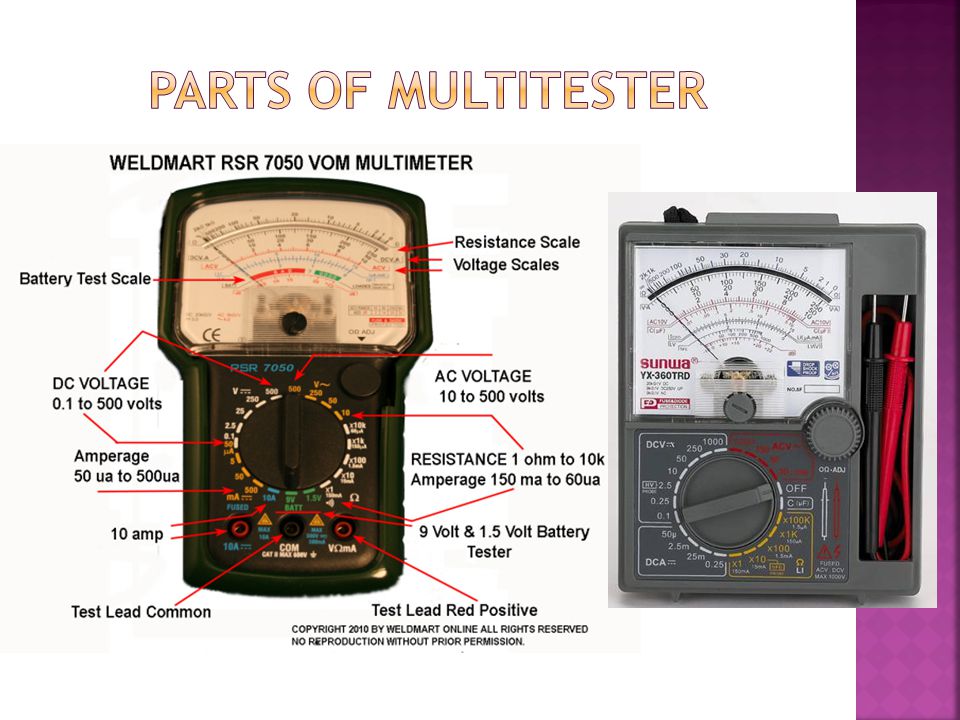
AA multimeter or a multitester is an electronic measuring instrument that combines several functions in one unit. TThe most basic instruments include an ammeter, voltmeter and ohmmeter. AAnalog multimeters are sometimes referred to as "volt-ohm-meters", abbreviated VOM. DDigital multimeters are usually referred to as "digital-multi-meters", abbreviated DMM. AA multimeter can be a handheld device useful for basic fault finding and field service work or a bench instrument

12
AAn analogue meter moves a needle along a scale. Switched range analogue multimeters are very cheap. The meter movement is delicate and dropping the meter is likely to damage it. EEach type of meter has its advantages. Used as a voltmeter, a digital meter is usually better because its resistance is much higher, 1 M ohm or 10 M ohm, compared to 200 ohm for a analogue multimeter on a similar range. OOn the other hand, it is easier to follow a slowly changing voltage by watching the needle on an analogue display. UUsed as an ammeter, an analogue multimeter has a very low resistance and is very sensitive, with scales down to 50 µA. More expensive digital multimeters can equal or better than this performance. MMost modern multimeters are digital and traditional analogue types are destined to become obsolete.

13
DDigital meters give an output in numbers, usually on a liquid crystal display. TThe central knob has lots of positions. WWe must choose which one is appropriate for the measurement you want to make. IIf the meter is switched to 20 V DC, for example, then 20 V is the maximum voltage which can be measured. TThis is sometimes called 20 V fsd, where fsd is short for full scale deflection. SSometimes, we will want to measure smaller voltages, and in this case, the 2 V or 200 mV ranges are used.

15
A meter is a measuring instrument. An ammeter measures current, A voltmeter measures the potential difference (voltage) between two points, and An ohmmeter measures resistance. A multimeter combines these functions, and possibly some additional ones as well, into a single instrument. Before going in to detail about multimeter, it is important to have a clear idea of how meters are connected into circuits. Diagrams in Next Slides show a circuit before and after connecting an ammeter
 between two points, and An ohmmeter measures resistance. A multimeter combines these functions, and possibly some additional ones as well, into a single instrument. Before going in to detail about multimeter, it is important to have a clear idea of how meters are connected into circuits. Diagrams in Next Slides show a circuit before and after connecting an ammeter.")
16
Ammeter An ammeter is an instrument that measures electric current. Types 1. DC Ammeter 2. AC Ammeter TTo measure current, the circuit must be broken to allow the ammeter to be connected in series. AAmmeters must have a LOW resistance. AAll the current flowing in the circuit must pass through the ammeter.

17
1. Select the current function 2. Select a range that is greater than the expected current 3. Physically interrupt the circuit 4. Observing polarity, connect the ammeter between the points created by the interruption.

18
Volt meter A voltmeter is an instrument that measures voltage Types of voltmeters 1. DC Volt meter 2. AC Volt meter TTo measure potential difference (voltage), the circuit is not changed: the voltmeter is connected in parallel. vvoltmeters must have a HIGH resistance. TThe voltmeter is connected in parallel between the two points where the measurement is to be made.
, the circuit is not changed: the voltmeter is connected in parallel. vvoltmeters must have a HIGH resistance. TThe voltmeter is connected in parallel between the two points where the measurement is to be made..")
19
1. Select the correct voltage function (AC or DC) for the type of voltage used in the circuit 2. Select a range that is greater than expected voltage 3. Determine the polarity of the voltage to be measured by looking at the schematic diagram or at the battery terminals (not for AC) 4. Connect the negative (black) lead of the multimeter to the negative end of the voltage to be measured. Connect the positive (red) lead of the meter to the positive end of voltage
 4. Connect the negative (black) lead of the multimeter to the negative end of the voltage to be measured. Connect the positive (red) lead of the meter to the positive end of voltage.")
20
Ohm meter It is an instrument that measure resistances. It is also used for checking the continuity of electrical circuits, coils of wires, heaters, etc. When measuring or testing with an ohmmeter, make sure the device to be tested is free from any source. i.e. no voltage across the device to be tested TTo measure resistance, the component must be removed from the circuit altogether OOhmmeters work by passing a small current through the component and measuring the voltage produced. IIf we try this with the component connected into a circuit with a power supply, the most likely result is that the meter will be damaged.

21
1. Remove power from the circuit 2. Select an appropriate range in the ohms function 3. When using, short (touch) the test leads. 4. Test the ohm adjust control until the pointer reads to zero ohm 5. Connect or touch the test leads to the terminals of the device whose resistance is to be measured
 the test leads. 4. Test the ohm adjust control until the pointer reads to zero ohm 5. Connect or touch the test leads to the terminals of the device whose resistance is to be measured.")
22
Megohmmeter IIt is an ohmmeter that can measure very high resistance WWhen cranked,it generates a DC voltage. The DC voltage is applied to the terminals of the equipment being tested for about one minute to test the strength of insulation resistance Applications 1. Test the insulation strength of wires and cables 2. Measure the insulation resistance of wires 3. Measure the insulation resistance between wire to ground

23
In the following example of using the megohmmeter,the test is made at the point where power leaves a motor starter Establishing a good ground Before the test is actually begun, it is necessary to establish a good ground. This is done by connecting the black (negative) test lead to ground and then grounding the red (positive) lead at another point. cranking the meter then tests the ground connection. If the dial moves to zero, the ground is good. This proves that the black lead is left in position while the test is done. Note: When the megohmmeter is being cranked, care must be taken not to touch the test leads because of the danger of electrical shock.
 test lead to ground and then grounding the red (positive) lead at another point. cranking the meter then tests the ground connection. If the dial moves to zero, the ground is good. This proves that the black lead is left in position while the test is done. Note: When the megohmmeter is being cranked, care must be taken not to touch the test leads because of the danger of electrical shock..")
24
The first step in using the meter is to test it to make sure that it is functioning correctly The next step is to prepare the equipment by De-energizing the component Verifying the power to the component is OFF Disconnecting the component from its circuit Connect the red lead to the bundle of wires Read the meter-Record this value Set the range switch to the discharge position-The purpose of the discharge position is to discharge the voltage stored uo in the equipment from the test. Safety Precaution: Do not disconnect the meter before the equipment has been discharged. The voltage present before discharging creates an electrical shock hazard Interpret the reading-to determine the quality of insulation

25
Thank You

Similar presentations

 Using Multimeters Karl Davies 1 East Kent Radio Society.>")


