Download presentation
Presentation is loading. Please wait.

1
Resistors in Series Introduction Two types of current are readily available, direct current (dc) and sinusoidal alternating current (ac) We will first consider direct current (dc) Insert Fig 5.1
 and sinusoidal alternating current (ac) We will first consider direct current (dc) Insert Fig 5.1")
2
Introducing the basic current flow of an electric circuit.

3
Defining the direction of conventional flow for single-source dc circuits.

4
Defining the polarity resulting from a conventional current I through a resistive element.

5
Resistors in series.

6
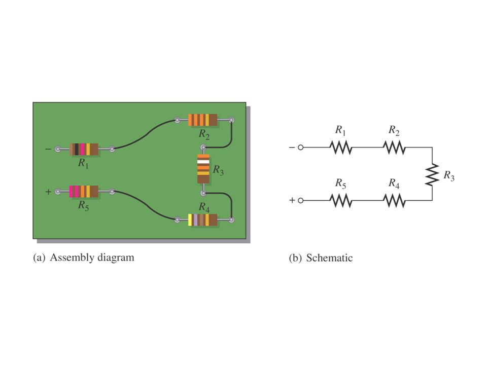
Schematic representation for a dc series circuit

7
Example of five resistors in series.

10
Series Resistors The total resistance of a series configuration is the sum of the resistance levels. The more resistors we add in series, the greater the resistance (no matter what their value).
..")
11
Resistance “seen” at the terminals of a series circuit.

12
Total Series Resistance The total resistance of a series circuit is equal to the sum of the resistances of each individual series resistor

13
Series connection of resistors.

14
Using an ohmmeter to measure the total resistance of a series circuit.

15
Two series combinations of the same elements with the same total resistance.

16
Series connection of resistors

17
Series combination of resistors

18
Series Resistors When series resistors have the same value, Where N = the number of resistors in the string. The total series resistance is found by multiplying the value of the same resistor times the number of resistors

19
Series connection of four resistors of the same value

20
Four 2.2Kohms resistors

21
Resistors in Series A series circuit provides only one path for current between two points so that the current is the same through each series resistor

22
Current in a Series Circuit The current is the same through all points in a series circuit The current through each resistor in a series circuit is the same as the current through all the other resistors that are in series with it Current entering any point in a series circuit is the same as the current leaving that point

23
Current entering any point in a series circuit is the same as the current leaving that point.

24
Current is the same at all points in a series circuit.

25
Series Circuits Total resistance (R T ) is all the source “sees.” Once R T is known, the current drawn from the source can be determined using Ohm’s law: Since E is fixed, the magnitude of the source current will be totally dependent on the magnitude of R T
 is all the source sees. Once R T is known, the current drawn from the source can be determined using Ohm’s law: Since E is fixed, the magnitude of the source current will be totally dependent on the magnitude of R T")
26
Ohm’s Law in Series Circuits Current through one of the series resistors is the same as the current through each of the other resistors and is the total current If you know the total voltage and the total resistance, you can determine the total current by using: I T = V T /R T

28
Measuring the current throughout the series circuit

29
Find R T then find I S

30
Find Current in circuit ?

31
Find the voltage of the Source ?

32
Find the voltage of the Source

33
Ohm’s Law in Series Circuits Current through one of the series resistors is the same as the current through each of the other resistors and is the total current If you know the voltage drop across one of the series resistors, you can determine the current by using:I = V R /R

34
Notation Single-subscript notation The single-subscript notation V a specifies the voltage at point a with respect to ground (zero volts). If the voltage is less than zero volts, a negative sign must be associated with the magnitude of V a.

35
Notation Double-subscript notation Because voltage is an “across” variable and exists between two points, the double-subscript notation defines differences in potential. The double-subscript notation V ab specifies point a as the higher potential. If this is not the case, a negative sign must be associated with the magnitude of V ab. The voltage V ab is the voltage at point (a) with respect to point (b).
 with respect to point (b)..")
36
Inserting the polarities across a resistor as determined by the direction of the current

37
Ohm’s Law in Series Circuits If you know the total current, you can find the voltage drop across any of the series resistors by using:V R = I T R The polarity of a voltage drop across a resistor is positive at the end of the resistor that is closest to the positive terminal of the voltage source The resistor current is in a direction from the positive end of the resistor to the negative end

38
Voltage in a Series dc circuit to be analyzed

39
Using voltmeters to measure the voltages across the resistors

40
Series circuit to be investigated

41
Series circuit to be analyzed

42
The source voltage appears across the open series resistor

43
Voltage Sources in Series When two or more voltage sources are in series, the total voltage is equal to the the algebraic sum (including polarities of the sources) of the individual source voltages
 of the individual source voltages")
44
Reducing series dc voltage sources to a single source.

47
Series connection of dc supplies: (a) four 1.5 V batteries in series to establish a terminal voltage of 6 V; (b) incorrect connections for two series dc supplies; (c) correct connection of two series supplies to establish 60 V at the output terminals.
 four 1.5 V batteries in series to establish a terminal voltage of 6 V; (b) incorrect connections for two series dc supplies; (c) correct connection of two series supplies to establish 60 V at the output terminals.")
49
Kirchhoff’s Voltage Law The applied voltage of a series circuit equals the sum of the voltage drops across the series elements: The sum of the rises around a closed loop must equal the sum of the drops. The application of Kirchhoff’s voltage law need not follow a path that includes current-carrying elements. When applying Kirchhoff’s voltage law, be sure to concentrate on the polarities of the voltage rise or drop rather than on the type of element. Do not treat a voltage drop across a resistive element differently from a voltage drop across a source.

50
Kirchhoff’s Voltage Law Kirchhoff’s voltage law (KVL) states that the algebraic sum of the potential rises and drops around a closed loop (or path) is zero.
 states that the algebraic sum of the potential rises and drops around a closed loop (or path) is zero.")
51
Kirchhoff’s Voltage Law The algebraic sum of all the voltage drops around a single closed loop in a circuit is equal to the total source voltage in that loop V S = V 1 + V 2 + V 3 + … + V n

52
Applying Kirchhoff’s voltage law to a series dc circuit.

53
Another Way to state Kirchhoff’s Voltage Law The algebraic sum of all voltages (both sources and drops) around a closed path is zero V S - V 1 - V 2 - V 3 - … - V n = 0
 around a closed path is zero V S - V 1 - V 2 - V 3 - … - V n = 0")
54
Illustration of a verification of Kirchhoff’s voltage law.

55
Sum of n voltage drops equals the source voltage.

56
Voltage Dividers Since each resistor has the same current, the voltage drops are proportional to the resistance values

57
The voltage divider as a bias circuit for a transistor amplifier.

58
Voltage-Divider Formula The voltage drop V x across any resistor or combination of resistors in a series circuit is equal to the ratio of that resistance value R x to the total resistance R T, multiplied by the source voltage V S V x = (R x /R T )V S
V S")
59
Potentiometer as an Adjustable Voltage Divider The potentiometer shown below is equivalent to a two- resistor voltage divider that can be manually adjusted The two resistors are between terminals 1 & 3 and 2 & 3

61
Adjusting the voltage divider.

62
A voltage divider used for volume control.

63
A potentiometer voltage divider used as an automotive fuel-level sensor.

64
Example of a two-resistor voltage divider.

65
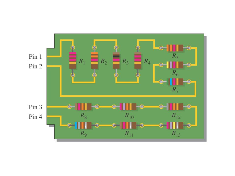
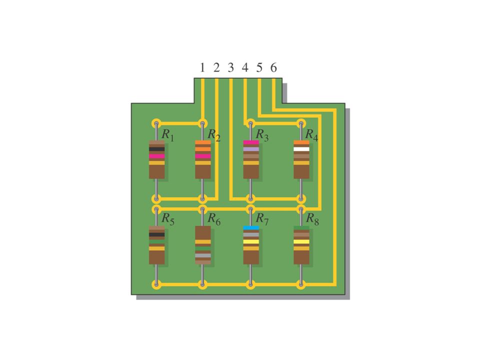
A five-resistor voltage divider.

66
Circuit Ground Voltage is relative The voltage at one point in a circuit is always measured relative to another point This reference point in a circuit is usually the ground point

67
Measuring Voltages with Respect to Ground When voltages are measured with respect to ground in a circuit, one meter lead is connected to the circuit ground, and the other to the point at which the voltage is to be measured

68
Simple illustration of circuit ground.

69
Measuring a voltage with respect to negative ground.

70
. Measuring Voltages with Respect to Ground

71
Measuring voltages at several points in a circuit with respect to ground

72
Series circuit (without a short) with correct voltages marked.
 with correct voltages marked.")
73
Measuring Voltage Across an Ungrounded Resistor Voltage can normally (as long as the meter is isolated from the power line ground) be measured across a resistor even though neither side of the resistor is connected to circuit ground The reading will be the voltage drop across the resistor
 be measured across a resistor even though neither side of the resistor is connected to circuit ground The reading will be the voltage drop across the resistor")
74
Measuring voltage directly across a resistor.

75
Open Circuit The most common failure in a series circuit is an open When an open occurs in a series circuit, all of the source voltage appears across the open

76
The source voltage appears across the open series resistor.

77
Ohm’s Law in Series Circuits An open in a series circuit prevents current; and, there is zero voltage drop across each series resistor The total voltage appears across the points between which there is an open

78
An open in a circuit prevents current.

79
Troubleshooting a series circuit for an open using half-splitting.

80
Short Circuit When there is a short, a portion of the series resistance is bypassed, thus reducing the total resistance A short in a series circuit results in more current than normal through the circuit The voltage across a shorted series component (or circuit) is 0 volts
 is 0 volts")
81
A Short in a Series Circuit

82
Example of shorts on a PC board.

83
Power in a Series Circuit The total amount of power in a series resistive circuit is equal to the sum of the powers in each resistor in series P T = P 1 + P 2 + P 3 +... + P n

84
Power Distribution in a Series Circuit The power applied by the dc supply must equal that dissipated by the resistive elements.

85
Power in a Resistor The amount of power in a resistor is important because the power rating of the resistor must be high enough to handle the expected power in the circuit

86
Series circuit to be investigated for Power

87
Identifying Parallel Circuits If there is more than one current path (branch) between two separate points, and if the voltage between those two points also appears across each of the branches, then there is a parallel circuit between those two points
 between two separate points, and if the voltage between those two points also appears across each of the branches, then there is a parallel circuit between those two points")
88
Resistors in Parallel Each current path is called a branch A parallel circuit is one that has more than one branch

90
Voltage in Parallel Circuits The voltage across any given branch of a parallel circuit is equal to the voltage across each of the other branches in parallel

91
Voltage across parallel branches is the same.

92
Kirchhoff’s current law: The current into a node equals the current out of that node.

93
Generalized Circuit Node Illustrating KCL

94
Total Parallel Resistance When resistors are connected in parallel, the total resistance of the circuit decreases The total resistance of a parallel circuit is always less than the value of the smallest resistor

95
Parallel Resistors For parallel elements, the total conductance is the sum of the individual conductance values. As the number of resistors in parallel increases, the input current level will increase for the same applied voltage.

96
Parallel Resistors For resistors in parallel, the total resistance is determined from Note that the equation is for the reciprocal of R T rather than for R T. Once the right side of the equation has been determined, it is necessary to divide the result into 1 to determine the total resistance

98
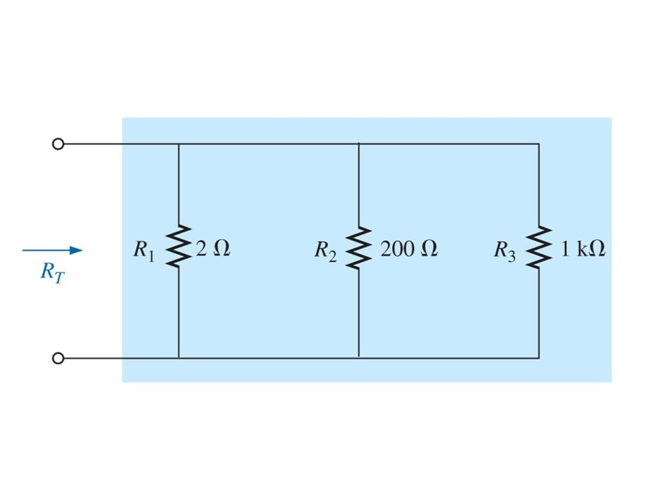
Parallel Resistors The total resistance of any number of parallel resistors can be determined using The total resistance of parallel resistors is always less than the value of the smallest resistor.

100
Connecting resistors in parallel reduces total resistance and increases total current.

101
Circuit with n resistors in parallel.

102
Notation for Parallel Resistors To indicate 5 resistors, all in parallel, we would write: R 1 ||R 2 ||R 3 ||R 4 ||R 5

105
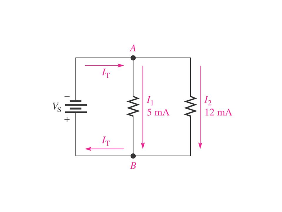
Illustration of a verification of Kirchhoff’s current law.

106
Total current divides between the two branches.

108
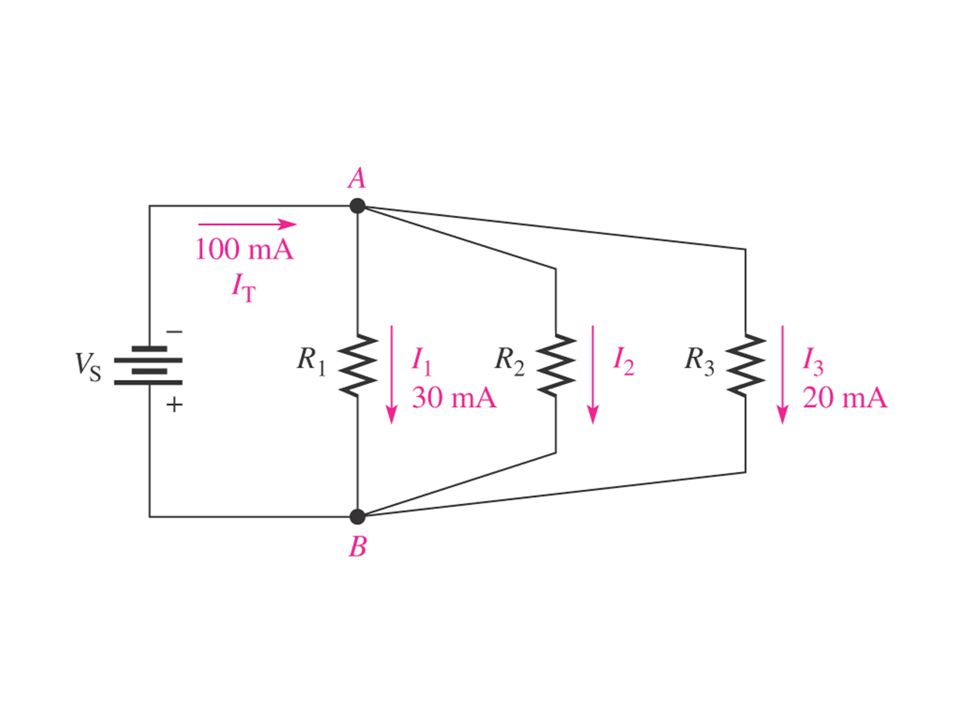
Generalized Circuit Node Illustrating KCL

109
Kirchhoff’s Current Law (KCL) The sum of the currents into a node (total current in) is equal to the sum of the currents out of that node (total current out) I IN(1) + I IN(2) +... + I IN(n) = I OUT(1) + I OUT(2) +... +I OUT(m)
 = I OUT(1) + I OUT(2) I OUT(m).")
110
Kirchhoff’s Current Law Kirchhoff’s current Law (KCL) can be stated another way: The algebraic sum of all the currents entering and leaving a junction is equal to zero
 can be stated another way: The algebraic sum of all the currents entering and leaving a junction is equal to zero")
111
FIGURE 5-18

112
Two-node configuration

113
Four-node configuration

114
.

115
Total Parallel Resistance When resistors are connected in parallel, the total resistance of the circuit decreases The total resistance of a parallel circuit is always less than the value of the smallest resistor

116
Formula for Total Parallel Resistance 1/R T = 1/R 1 + 1/R 2 + 1/R 3 +... + 1/R n

118
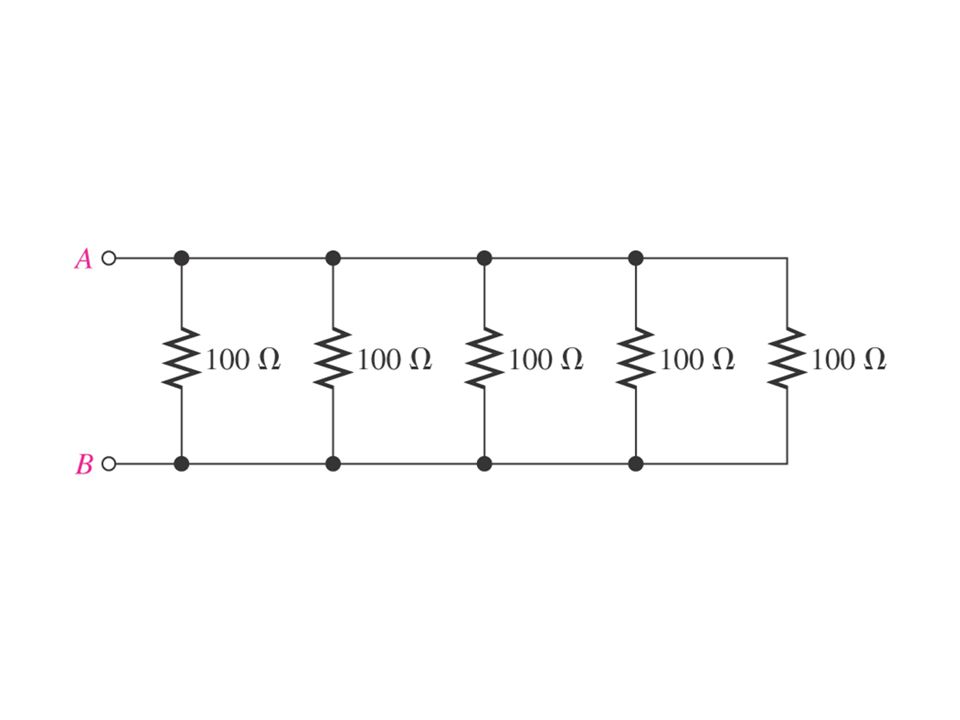
Parallel Resistors For equal resistors in parallel: Where N = the number of parallel resistors.

120
Two Resistors in Parallel The total resistance for two resistors in parallel is equal to the product of the two resistors divided by the sum of the two resistors R T = R 1 R 2 /(R 1 + R 2 )
")
121
Current Divider Rule The current divider rule (CDR) is used to find the current through a resistor in a parallel circuit. General points: For two parallel elements of equal value, the current will divide equally. For parallel elements with different values, the smaller the resistance, the greater the share of input current. For parallel elements of different values, the current will split with a ratio equal to the inverse of their resistor values.

122
Current Divider Rule

123
General Current-Divider Formula The current (I x ) through any branch equals the total parallel resistance (R T ) divided by the resistance (R x ) of that branch, and then multiplied by the total current (I T ) into the junction of the parallel branches I x = (R T /R x )I T
 through any branch equals the total parallel resistance (R T ) divided by the resistance (R x ) of that branch, and then multiplied by the total current (I T ) into the junction of the parallel branches I x = (R T /R x )I T")
125
Notation for Parallel Resistors To indicate 5 resistors, all in parallel, we would write: R 1 ||R 2 ||R 3 ||R 4 ||R 5

126
Application of a Parallel Circuit One advantage of a parallel circuit over a series circuit is that when one branch opens, the other branches are not affected

128
Current Dividers A parallel circuit acts as a current divider because the current entering the junction of parallel branches “divides” up into several individual branch currents

129
Current Dividers The total current divides among parallel resistors into currents with values inversely proportional to the resistance values

130
FIGURE 5-53

131
FIGURE 5-51 A 10 mA meter.

132
FIGURE 5-52 A milliammeter with three ranges.

135
General Current-Divider Formula The current (I x ) through any branch equals the total parallel resistance (R T ) divided by the resistance (R x ) of that branch, and then multiplied by the total current (I T ) into the junction of the parallel branches I x = (R T /R x )I T
 through any branch equals the total parallel resistance (R T ) divided by the resistance (R x ) of that branch, and then multiplied by the total current (I T ) into the junction of the parallel branches I x = (R T /R x )I T")
136
Open Branches When a parallel resistor opens, I T is always less than its normal value Once I T and the voltage across the branches are known, a few calculations will determine the open resistor when all the resistors are of different values

137
Open Branches When an open circuit occurs in a parallel branch, the total resistance increases, the total current decreases, and the same current continues through each of the remaining parallel paths

138
When a lamp filament opens, total current decreases by the amount of current in the lamp that opened. The other branch currents remain unchanged.

139
All parallel branches (open or not) have the same voltage.
 have the same voltage.")
140
Power in Parallel Circuits Total power in a parallel circuit is found by adding up the powers of all the individual resistors, the same as for series circuits P T = P 1 + P 2 + P 3 +... + P n

141
Power flow in a dc parallel network.

142
When a lamp filament opens, total current decreases by the amount of current in the lamp that opened. The other branch currents remain unchanged.

143
All parallel branches (open or not) have the same voltage
 have the same voltage")
144
Voltmeter Loading Effects Voltmeters are always placed across an element to measure the potential difference. The resistance of parallel resistors will always be less than the resistance of the smallest resistor. A DMM has internal resistance which may alter the resistance of the network under test. The loading of a network by the insertion of a meter is not to be taken lightly, especially if accuracy is a primary consideration.

145
Voltmeter Loading Effects A good practice is to always check the meter resistance against the resistive elements of the network before making a measurement. Most DMMs have internal resistance levels in excess of 10 M on all voltage scales. The internal resistance of a VOM depends on the scale chosen. Internal resistance is determined by multiplying the maximum voltage of the scale setting by the ohm/volt ( / V) rating of the meter, normally found at the bottom of the face of the meter.
 rating of the meter, normally found at the bottom of the face of the meter..")
146
Voltmeter loading.

147
Applications Car system The electrical system on a car is essentially a parallel system. Parallel computer bus connections The bus connectors are connected in parallel with common connections to the power supply, address and data buses, control signals, and ground.

148
Expanded view of an automobile’s electrical system.

149
Application of a Parallel Circuit One advantage of a parallel circuit over a series circuit is that when one branch opens, the other branches are not affected

150
Applications House wiring Except in some very special circumstances the basic wiring of a house is done in a parallel configuration. Each parallel branch, however, can have a combination of parallel and series elements. Each branch receives a full 120 V or 208 V, with the current determined by the applied load.

151
Application of a Parallel Circuit All lights and appliances in a home are wired in parallel The switches are located in series with the lights

Similar presentations


 LECTURE # 14 BY MOEEN GHIYAS.>")

 LECTURE # 11 BY MOEEN GHIYAS.>")


