Download presentation
Presentation is loading. Please wait.

1
Funded by Workforce Central Florida Mentor: Alan Shaffer - Lakeland Electric Photovoltaic MPPT Charge Controller (PMC 2 ) Group 10 Amber Scheurer, EE Eric Ago, EE Sebastian Hidalgo, EE Steven Kobosko, EE
 Group 10 Amber Scheurer, EE Eric Ago, EE Sebastian Hidalgo, EE Steven Kobosko, EE")
2
MPPT Charge Controller Solar Array Battery LCD Wireless Inverter System Overview We designed a charge controller that implements MPPT and demonstrates it in a fully functional stand- alone photovoltaic system.

3
Motivation and Value of Project Maximize the cost return on investment for solar panels by using Maximum Power Point Tracking (MPPT) algorithms LCD screen and wireless data transfer Useful for testing, research, and maintenance Potential for industrial scaling Incorporate a charge controller system with one controller per panel
 algorithms LCD screen and wireless data transfer Useful for testing, research, and maintenance Potential for industrial scaling Incorporate a charge controller system with one controller per panel")
4
Goals Charge controller has to be inherently low power Utilize Maximum Power Point Tracking to increase efficiency User/Researcher Friendly Design LCD Screen Wireless Data Transfer to Computer Station Inexpensive

5
Specifications Solar Panel delivers > 14 V Total System Power Output > 200 W 12 V Battery with > 30 Ah Wireless range > 20 m Approximately 90% Efficient

6
LCD Screen Boost Buck Current Sensor Voltage Sensor Charge Controller PV Panel Temp. Sensor Micro Controller XBee MCU Battery Inverter Temp. Sensor Current Sensor Voltage Sensor Light Sensor

7
Solar Panel ParameterSiemens SP75 Rated Power75 W TypeSingle-Crystal Rated Voltage V MPP 17.0 V Rated Current I MPP 4.4 A Open Circuit Voltage21.7 V Short Circuit Current4.8 A Provided by Florida Solar Energy Center 20.8 in 47.3 in

8
Microcontroller ATmega328P ParameterArduino UNO ChipATmega328P Digital I/O14 Pins Analog Input6 Pins PWM Output6 Pins Communication Protocols I2C, Serial 2.7 in Arduino Bootloader Arduino Bootloader Open Source Open Source 2.1 in

9
Microcontroller Peripherals ATmega 328P XBee RX TX Irradiance Sensor D2 LCD TX (D4) Temperature Sensors Voltage Sensors Current Sensors SCL A3 SDA A2 A0 A1 Buck- Boost Circuitry PWM
 Temperature Sensors Voltage Sensors Current Sensors SCL A3 SDA A2 A0 A1 Buck- Boost Circuitry PWM")
10
Current Sensor ACS711ELCTR-12AB-T ParameterACS711 Sensor TypeHall Effect Operating Voltage3 – 5.5 V Current Sensing -12 – +12 A Operating Temp.-40 – 85 °C 4.9 mm 6 mm

11
Voltage Sensor Voltage Divider ParameterVoltage Divider SourcePV panel Sensor TypeVoltage Divider Voltage Sense0 – 21 V R12.7 kΩ R210 kΩ Output Voltage0 – 5 V R2=10kΩ R1=2.7kΩ VoVo

12
Irradiance Sensor TSL235R-LF ParameterTSL235R-LF Operating Voltage 5 V Output Square wave 50% Duty Cycle Operating Temp.-25 – 70 °C Light Wavelength Range 320 – 1050 nm Output Frequency200 – 1000 KHz 4.6 mm 19.46 mm

13
Temp Sensor DS1624 ParameterDS1624 Operating Voltage3 – 5V Temp. Range-55 – 125° C Internal Memory E 2 256 Bytes ProtocolI2C 8.5 mm 9 mm

14
LCD Screen Parameter20 x 4 LCD CommunicationSerial ColorBlack on Green Operating Voltage5 V Max Current60 mA

15
Wireless Module 24.3 mm 27.6 mm ParameterXbee Series 1 Protocol802.15.4 CommunicationSerial Transmitting Power 1 mW Outdoor Range90 m Frequency Band2.4 GHz Operating Voltage3.3 V

16
Wireless Subsystem Sensor Data

17
Battery Sun Xtender PVX-420T ParameterSun Xtender ChemistryAGM Nominal Voltage12 V Capacity42 Ah CCA40 A Number of Charges 1000 7.71 in 8.05 in 5.18 in

18
Inverter Cobra CPI 880 ParameterCPI 880 Output Power800 W Surge1600 W Wave outputModerate Sine Input Voltage12 V Output Voltage109 – 120 VAC AC Outlets2 USB1 3 in. 5.5 in 9 in.

19
H-Bridge Topology Buck-Boost DC/DC Regulator Single Inductor Buck/Boost Architecture Separate Buck and Boost Operating Modes Synchronous 4-Switch Operation for Higher Efficiency Wide Input Voltage Range: 4.5V to 40V Wide Output Voltage Range: 12V to 15V

20
Boost Operation

21
Buck Operation

22
MPPT Algorithms EfficiencyProgramming Difficulty Potential for “error” Incremental Conductance Method HighestComplexYes Perturb and Observe Method HighAverageYes Constant Voltage Method Low No

23
Voltage Power MPP P max V OC Perturb and Observe Method V mp

24
Battery Charging Stages BulkAbsorptionFloat

25
Adjust PWM Start Sensor Read: Battery Voltage Sensor Read: Battery Current Float or Absorption I > I 0 I < I 0 Increase Voltage Decrease Voltage Bulk Regulated Power Delivered to Battery LCD: LCD.print Xbee: Serial.write

26
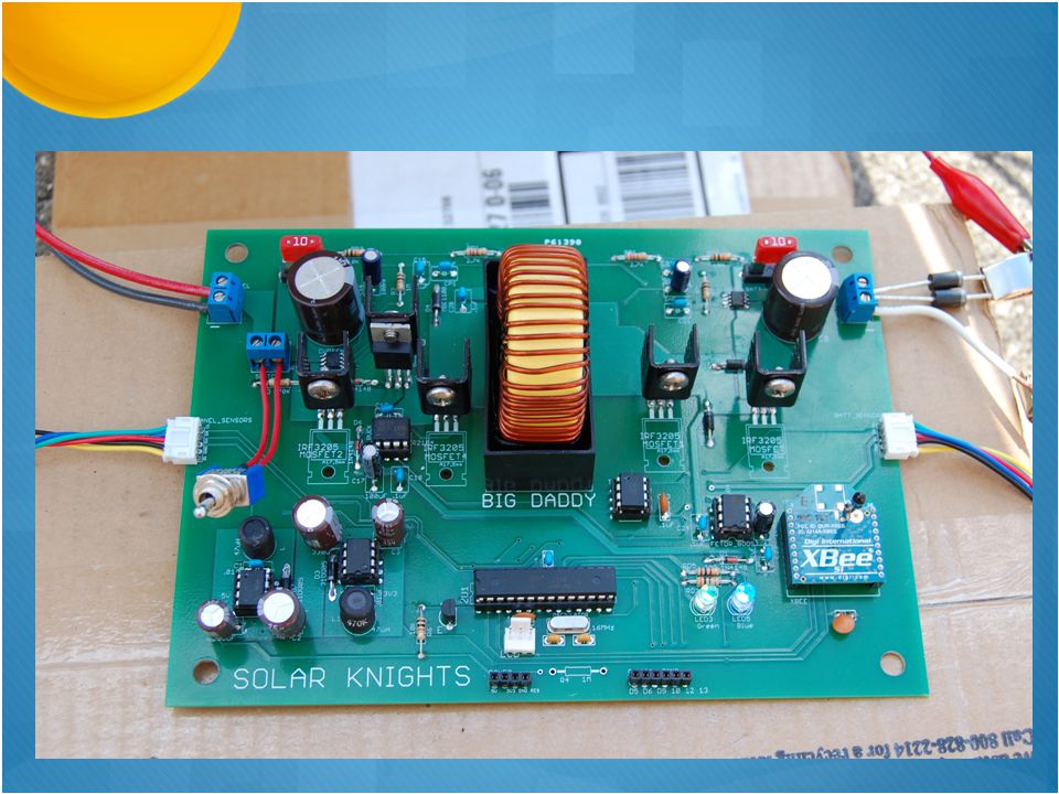
Printed Circuit Board Schematic

28
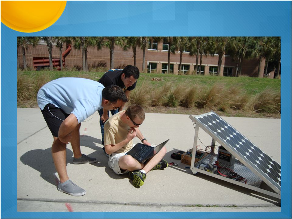
Testing: Drawing 4.29 A

29
2.0 A 3.4 A 12.5 V 17.3 V

30
Parts ListCost per partNumber of partsTotal Cost Solar Panel Siemens SP75 75W ModuleLoaned1$0.00 Charge Controller Printed Circuit Board (Student Special)$33.002$66.00 Serial Enabled 20x4 LCD - Black on Green 5V$29.951 Sensors$14.001 Electrical Circuit Components$215.001 Misc Lab Supplies (Bread Board, wire, solder, etc.)$48.001 Battery Sun Xtender PVX-420T$156.881 Inverter/Outputs Cobra CPI 880$80.001 Microcontroller Arduino Uno SMD (ATmega328)$30.001 Wireless Components Xbee Explorer Board$24.001 Xbee Module$26.002$52.00 Mounting Misc Parts for Mounting (Aluminum, Wheels, etc.)$108.001 Total:$715.83
$33.002$66.00 Serial Enabled 20x4 LCD - Black on Green 5V$ Sensors$ Electrical Circuit Components$ Misc Lab Supplies (Bread Board, wire, solder, etc.)$ Battery Sun Xtender PVX-420T$ Inverter/Outputs Cobra CPI 880$ Microcontroller Arduino Uno SMD (ATmega328)$ Wireless Components Xbee Explorer Board$ Xbee Module$26.002$52.00 Mounting Misc Parts for Mounting (Aluminum, Wheels, etc.)$ Total:$715.83")
32
Questions?

Similar presentations


>")
>")

 Group 8 Andrés F. Suárez (EE) Brian Maldonado (EE) Rígel Jiménez (EE)>")


>")


