Download presentation
Presentation is loading. Please wait.

1
VAD Resource Team University of Washington Medical Center
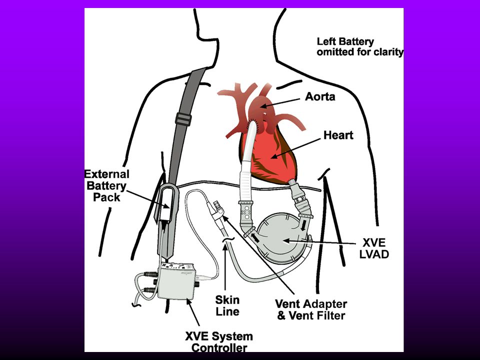
HeartMate XVE LVAD VAD Resource Team University of Washington Medical Center

2
VAD Resource Team Pager/Phone Email Cardiac Surgery Shauna Andrus
sandrus 5NE/5SE Sheryl Greco sagreco 5NE Kristina Green kegreen 5SE Nicola Kaye kiwi 5SE Janie Shively janie 5NE Eileen Suver esuver 5SE Teddy Villamarin pinoy

3
Heart Failure Heart failure is defined as the inability of the heart to effectively pump oxygenated blood to meet the metabolic demands of the body. This devastating condition affects 4.7 million people a year in the United States alone. When conventional medical therapies are unsuccessful, cardiac transplantation is an option for treatment and to prolong life. Unfortunately, only 2300 patients each year receive heart transplants, because the number of patients awaiting transplants far exceeds the number of organs available.

4
HeartMate Candidates Transplant candidate:
dependent on vasopressor support OR incomplete response to continued vasopressor support Approved for ‘Destination Therapy’ BSA of 1.5 or greater

9
Pump Percutaneous Tube Vent Adapter
Weight: 3.74 lbs Pump volume: 83 ml Rate: Up to 120 Flow: Up to 10 L/min Titatanium Motor with 2 bearings Vent port Two tissue valves: Inflow & Outflow

10
Inside surface of pump housing

11
Pump weighs 2.63 pounds Titanium case Inside surfaces textured to encourage natural formation of a lining that mimics intima Clot formation inside the pump not a concern because of the lining Coumadin not used ASA daily to prevent platelet aggregation which helps to prevent antibody formation Pump stroke volume is 83 ml Normal volume of blood pumped each cycle is about 90% of the 83 ml Typical stroke volume for a patient is in the low 70s Pump works via microprocessing chip that runs a motor encased inside the pump. Motor drives a pusher plate up, forcing blood out of the pump Percutaneous lead is tunneled under the skin from the pump on the left side to the exit site on the right This helps prevent infection at the exit site from traveling to the pocket where the actual pump is More comfortable for the patient Allows easier activity

12
Percutaneous Tube & Vent Adapter
AVOID: WATER & POWDER AROUND FILTER Percutaneous lead Tunneled from pump to the surface of the skin Contains an electrical cable and an air tube Once the lead emerges from the body, it separates at the Y-connector into an electric connector and an air vent Our patients have had problems with broken Y-connectors The company has developed a new Y-connector that will be introduced sometime this year Air Vent Purpose is to allow free moving air in the system Without free air movement, a vacuum would be created in the pump, causing malfunction The motor causes the pusher plate to move up, pushing blood into the aorta Air moves in under the pusher plate to fill the space When the pusher plate returns to its starting pooint, it pushes the air out of the way If the air didn’t move in and out, a vacuum would be created in the empty space and the pusher plate would not be able to return to its starting place Because this is an open line directly into the pump, it is vital that no fluids enter this line!!! Could cause the pump to seize and stoop working Like any piece of metal equipment, a little bit of fluid sitting in a motor can cause corrosion resulting in a malfunction Either way, this creates a major problem and can result in needing to emergently replace the implanted pump at high risk to the patient and a cost of $65,000! NO FLUID SHOULD EVER BE NEAR THE PORT! A simple filter is attached to the end of the port Non-occlusive to allow the air to flow Should never have an occlusive cap of any sort Will not prevent fluids from entering the line Collects dust Change weekly Electrical connector attaches to a cable on the system controller and provides transmission of information between the controller and the pump

13
System Controller “Quick” Connector

14
System Controller Cables

15
System Controller ‘Brains’ of system (computer)
Alarms: Audible & Visual Two cables: connect to power source ‘Quick connect’ to percutaneous lead

16
System Controller Change Mode Alarm Reset
Has three functions Controls the motor of the pump Assures that the pump is working correctly Provides a warning when things are not working correctly Worn at the waist on the right side of the body Three cables Single cable attaches to the electric cable of the percutaneous lead, allowing information to be passed back and forth Two cables are used to attach to the power source Two buttons Mode button (lower left corner of the controller) Selects auto and fixed modes of operation 1 beep = Fixed (one syllable) Present rate that VAD pumps at regardless of activity Used when the controller is unable to get information from the pump (switches into fixed mode automatically) When you want to control the pump rate to keep it from pumping too fast or too slow When the batteries are low 2 beeps = Auto (two syllables) Normal mode of operation Pump will adjust the rate to meet the demands of the patient, just like the normal heart rate adjusts Systems Check: Done daily and charted in CIS Press and hold the Mode button for 3 seconds Yellow wrench, red heart, red battery and fuel gauge lights will come on and a steady alarm will sound After 3 seconds, release the mode button. Lights remain lit and the alarm will sound for another 3 seconds All warning lights will turn off except for the yellow wrench. Warning lights will turn back on in less than 5 seconds and will stay on for another 5 seconds. The alarms continue to sound. If lights and alarms turn off after 5 seconds it means the controller cell needs to be replaced Courtesy dictates shutting the patient’s door and letting those around you know what is going on. Alarm Reset Button Resets alarms 5 minutes for yellow wrench 2 minutes for red heart Check battery life Press and hold while looking at the number of green battery lights showing Amount of battery life is approximate, since the amount of power used is based on pump workload and the age and condition of the batteries At < 25% available battery power, you should change to another power source! Battery Symbols If < 15 minutes of power remains, yellow battery symbol lights with audible beep 1/sec If < 5 minutes of power remains, red battery symbol will appear and a steady tone will sound Controller initiates Power Saver Mode, telling the pump to beat at 50 bpm This uses less battery energy and allows time to immediately switch to another power source A patient with a sudden decrease in HR may be symptomatic! Change Mode Alarm Reset System Check Battery Power Check
 Selects auto and fixed modes of operation. 1 beep = Fixed (one syllable) Present rate that VAD pumps at regardless of activity. Used when the controller is unable to get information from the pump (switches into fixed mode automatically) When you want to control the pump rate to keep it from pumping too fast or too slow. When the batteries are low. 2 beeps = Auto (two syllables) Normal mode of operation. Pump will adjust the rate to meet the demands of the patient, just like the normal heart rate adjusts. Systems Check: Done daily and charted in CIS. Press and hold the Mode button for 3 seconds. Yellow wrench, red heart, red battery and fuel gauge lights will come on and a steady alarm will sound. After 3 seconds, release the mode button. Lights remain lit and the alarm will sound for another 3 seconds. All warning lights will turn off except for the yellow wrench. Warning lights will turn back on in less than 5 seconds and will stay on for another 5 seconds. The alarms continue to sound. If lights and alarms turn off after 5 seconds it means the controller cell needs to be replaced. Courtesy dictates shutting the patient’s door and letting those around you know what is going on. Alarm Reset Button. Resets alarms. 5 minutes for yellow wrench. 2 minutes for red heart. Check battery life. Press and hold while looking at the number of green battery lights showing. Amount of battery life is approximate, since the amount of power used is based on pump workload and the age and condition of the batteries. At < 25% available battery power, you should change to another power source! Battery Symbols. If < 15 minutes of power remains, yellow battery symbol lights with audible beep 1/sec. If < 5 minutes of power remains, red battery symbol will appear and a steady tone will sound. Controller initiates Power Saver Mode, telling the pump to beat at 50 bpm. This uses less battery energy and allows time to immediately switch to another power source. A patient with a sudden decrease in HR may be symptomatic! Change Mode Alarm Reset. System Check Battery Power Check.")
17
Power Base Unit (PBU) & System Monitor
 & System Monitor")
18
Power Base Unit PBU Internal battery Battery charger AC Fail Low Batt
Alarm reset

19
Screen of System Monitor
Pump Rate: Rate PUMP is beating Flow: Cardiac output Stroke volume: ml/beat FUNCTION BUTTONS Auto/Fixed Fixed Rate Fixed Rate

20
FIXED vs. AUTO MODE FIXED MODE is a set rate the pump will beat at regardless of other conditions. This rate can be adjusted by using the system monitor, and should always be set at a rate close to the patient’s baseline. AUTO MODE is responsive to the filling and emptying of the LVAD pump. The pump fills to a fixed volume at a variable rate depending on the patient’s activity and volume status. NO RELATIONSHIP TO RATE OR RHYTHM OF HEART

21
Display Module DISPLAY Provides information ONLY No button interface

22
Components:Tethered Quick Connect: percutaneous tube to system controller Power Base Unit Cable: connecting cable from PBU to system controller Twist together connection: system controller to power base unit cable VE LVAD Percutaneous lead Y-connector External air vent Electrical connection System Controller PBU cable Power base unit System monitor Power cord Rear panel of PBU Display Module Hand Pump Emergency Power Pack Stroke Volume Limiter Pneumatic console

23
Components: Battery Powered
Requires 2 batteries 4-6 hours of power/set Worn in holster Quick Connect Twist together connect: system controller to battery

24
Hand Pump: Goes with patient EVERYWHERE
Emergency Power Pack

25
Battery Clips & Batteries

26
Changing Power Sources

27
YELLOW WRENCH: ADVISORIES
1 beep per second May be silenced for 24 hours RED HEART: HAZARD ALARMS Steady tone alarm Preceded and accompanied by a Yellow Wrench alarm YELLOW WRENCH ALERTS 1 beep per second May be silenced RED HEART ALARMS Steady tone alarm Preceded and accompanied by a yellow wrench alarm May be reset for 2 minutes May be reset for 2 minutes

28
YELLOW WRENCH Power Cable Disconnect
MOST COMMON Routine alarm that sounds when power source (battery or outlet) is changed or only one power source connected Check the connections to the power source
 is changed. or only one power source connected. Check the connections to the power source.")
29
YELLOW WRENCH 2. Controller Malfunction Caused by a malfunction in the
2nd MOST COMMON Caused by a malfunction in the system controller *Inoperative Controller = ½ wrench* Change the system controller

30
Occurs when pump has higher than normal pressure to pump against
YELLOW WRENCH 3. Power Limit Advisory RARE Occurs when pump has higher than normal pressure to pump against Kinked or occluded vent line replace the extension High blood pressure to pump against lower blood pressure Outflow obstruction requires surgery Kink or obstruction at vent line check for and remove kinks or obstructions, change the vent filter

31
Occurs when pump is changed to Fixed Mode and the preset rate is:
YELLOW WRENCH 4. Rate Control Fault RARE Occurs when pump is changed to Fixed Mode and the preset rate is: Less than 50 or Greater than 120 Pump defaults to 72 beats per minute correct by attaching the system monitor and changing the backup rate

32
YELLOW WRENCH: ADVISORIES
1 beep per second May be silenced for 24 hours RED HEART: HAZARD ALARMS Steady tone alarm Preceded and accompanied by a yellow wrench alarm YELLOW WRENCH: ADVISORIES 1 beep per second May be silenced for 24 hours RED HEART: HAZARD ALARM Steady tone alarm Preceded and accompanied by a yellow wrench alarm May be reset for 2 minutes May be reset for 2 minutes

33
THIS IS A CRITICAL ALARM
RED HEART Low Beat Rate or No Op Low Beat Rate: Pump slows to < 30 bpm No Op: may be stopped THIS IS A CRITICAL ALARM AND CANNOT BE RESET

34
Check connections most likely culprit is the percutaneous tube connection to the system controller Check your patient you may need to hand pump Check the vent port to insure it is not occluded Try changing the power source Try changing the system controller

35
If pumping does not resume immediately, remove all power sources and start hand pumping
STAT page the perfusionist on call STAT page Surg C Attending or Fellow Call for pneumatic console (5NE) with Stroke Volume Limiter (SVL) Do NOT restart the pump if it has been off > 5 minutes except with order from Attending or Fellow
 with Stroke Volume Limiter (SVL) Do NOT restart the pump if it has been off > 5 minutes except with order from Attending or Fellow.")
36
2. Low Stroke Volume: < 25 ml
RED HEART 2. Low Stroke Volume: < 25 ml 3. Low Flow: < 1.5 L/min STAT page perfusion STAT page Surg C Attending or Fellow Consider changing to Fixed Mode to flow Assess whether this is a patient or equipment problem

37
RED HEART CAUSES Severe RV failure consider inotropes
Extreme low blood volume assess for bleeding or fluid loss, replace fluids VT, VF or Asystole ACLS protocols EXCEPTION: NO chest compressions (may dislodge outflow conduit) LV inflow cannula obstruction requires surgical intervention
 LV inflow cannula obstruction. requires surgical intervention.")
38
disconnected from the percutaneous tube
FLASHING YELLOW BATTERY RED HEART YELLOW WRENCH Steady tone CANNOT BE SILENCED XVE System Controller disconnected from the percutaneous tube Check system controller cable connection to percutaneous tube

39
BATTERY ALARMS Flashing Yellow Battery No tone Yellow Battery
Once-per-second Red Battery Continuous Audio Tone

40
FLASHING YELLOW BATTERY No tone
Battery Module The battery that controls the alarm lights and tones on the system controller is low This battery controls ONLY the alarm tones and lights, NOT the pump Change the battery, then do a controller self-test to clear the alarm

41
YELLOW BATTERY Once-per-second BEEP
Low Voltage Advisory Less than 15 min of battery power remain Change to alternate power source

42
RED BATTERY: Steady tone
Low Voltage Alarm Less than 5 minutes of battery power remains Pump defaults to POWER SAVER MODE: 50 bpm Patient may be this rate if used to faster rate Immediately switch to an alternate power source or prepare to hand pump

43
EMERGENCIES VT/VF BLOOD FROM EXIT SITE RED HEART
Monitor BP; Flows; Cardiovert/Defibrillate BLOOD FROM EXIT SITE STAT page CT surgeon &/or fellow RED HEART Trouble shoot; be prepared to hand pump

44
IF LVAD MOTOR STOPS < 5 minutes > 5 minutes
Troubleshoot and get it working again Try hand pumping Replace system controller Try pneumatic console (with SVL) > 5 minutes DO NOT attempt to restart motor STAT page perfusionist STAT page Surg C Attending/Fellow
 > 5 minutes. DO NOT attempt to restart motor. STAT page perfusionist. STAT page Surg C Attending/Fellow.")
45
Pneumatic Console Can drive XVE HeartMate if pump failure Must use STROKE VOLUME LIMITER Pneumatic tubing with flutter diaphragm FIXED only available mode No electric connections to provide pump information Consider transfer to 5SE No alarms on IP console

46
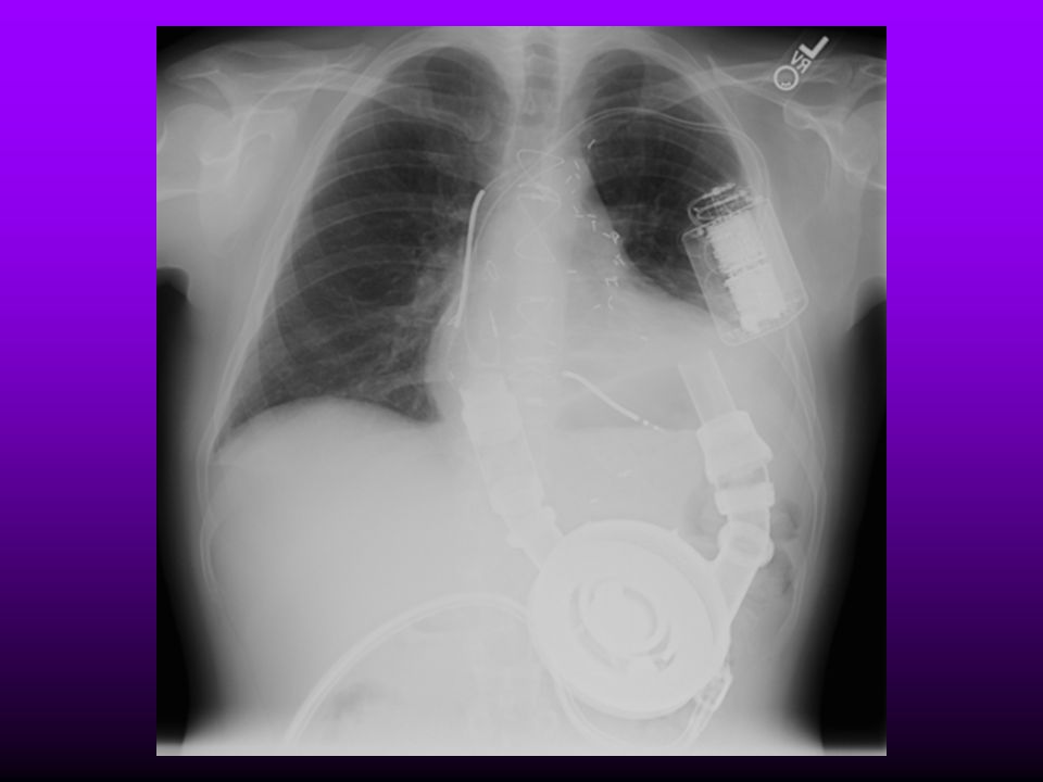
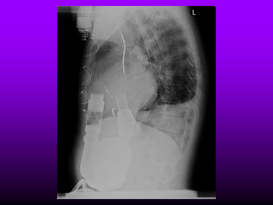
Three months after implant

47
University of Washington Medical Center 1997-2006
Device Total TX Waiting/ Current IP HeartMate 19 17 VE HeartMate 22 20 XVE HeartMate 26 23 1 Thoratec PVAD 24 5 Thoratec IVAD 2 XVE HeartMate DT/HM II DT 4 HM II 7 TOTAL 102* 66 *4 Combo HeartMate + Thoratec

Similar presentations


 are a proven therapy as bridge-to-cardiac transplantation in Class IIIB and Class IV heart failure patients.>")
 to power the HeartMate II or XVE LVAS and optional Display Module or System Monitor, prepare the.>")


 restricts this device to sale by or on the order of a physician. Refer to the “Instructions For Use” for complete Indications.>")
 restricts this device to sale by or on the order of a physician. Refer to the “Instructions For Use” for complete Indications.>")
 are a proven therapy as bridge-to-cardiac transplantation in Class IIIB and Class IV heart failure patients.>")


 Patient Clinical-xxx Rev001.>")

