Download presentation
Presentation is loading. Please wait.

1
LESSON THREE

2
CONNECTING RODS

5
1.DEFINITION *

6
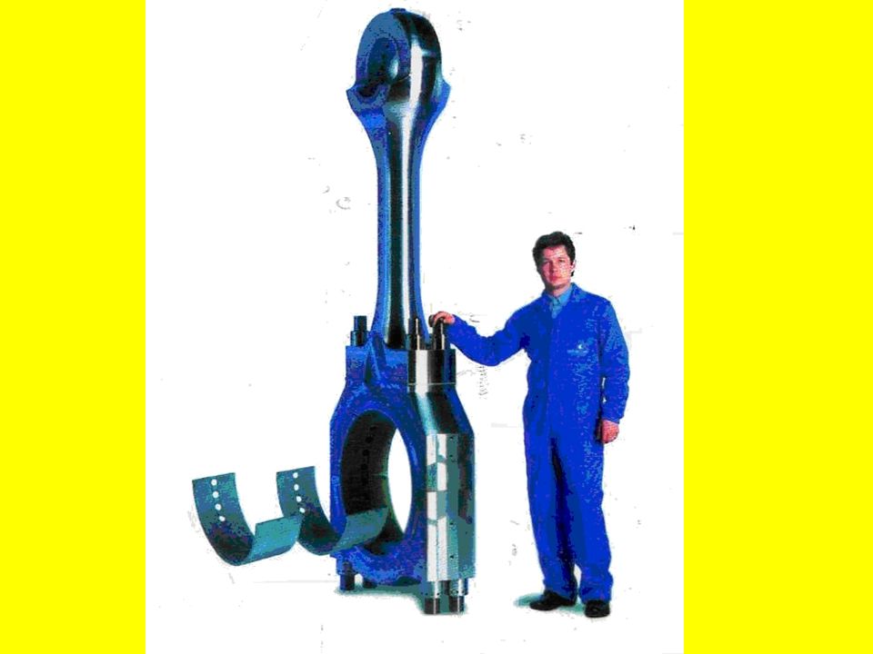
A running component connecting the crankshaft to the piston ( in trunk piston engines ) or to the crosshead ( in crosshead engines ). It has both linear ( reciprocating, up-and-down ) & rotational ( rotary ) motion.
 & rotational ( rotary ) motion..")
8
1.DEFINITION * A running component connecting the crankshaft to the piston ( in trunk piston engines ) or to the crosshead ( in crosshead engines ). It has both linear ( reciprocating, up-and-down ) & rotational ( rotary ) motion. 2. FUNCTION
 & rotational ( rotary ) motion. 2. FUNCTION.")
9
1.DEFINITION * A running component connecting the crankshaft to the piston ( in trunk piston engines ) or to the crosshead ( in crosshead engines ). It has both linear ( reciprocating, up-and-down ) & rotational ( rotary ) motion. 2. FUNCTION Primary function: to transmit the push ( pressure, thrust ) of the piston to the crankshaft, either directly or indirectly.
 & rotational ( rotary ) motion. 2. FUNCTION Primary function: to transmit the push ( pressure, thrust ) of the piston to the crankshaft, either directly or indirectly..")
10
1.DEFINITION * A running component connecting the crankshaft to the piston ( in trunk piston engines ) or to the crosshead ( in crosshead engines ). It has both linear ( reciprocating, up-and-down ) & rotational ( rotary ) motion. 2. FUNCTION Primary function: to transmit the push ( pressure, thrust ) of the piston to the crankshaft, either directly or indirectly. Secondary function: ( in most designs ) to convey cooling oil to the pistons which demands for a quite a large diameter passage
 & rotational ( rotary ) motion. 2. FUNCTION Primary function: to transmit the push ( pressure, thrust ) of the piston to the crankshaft, either directly or indirectly. Secondary function: ( in most designs ) to convey cooling oil to the pistons which demands for a quite a large diameter passage.")
11
1.DEFINITION * A running component connecting the crankshaft to the piston ( in trunk piston engines ) or to the crosshead ( in crosshead engines ). It has both linear ( reciprocating, up-and-down ) & rotational ( rotary ) motion. 2. FUNCTION Primary function: to transmit the push ( pressure, thrust ) of the piston to the crankshaft, either directly or indirectly. Secondary function: ( in most designs ) to convey cooling oil to the pistons which demands for a quite a large diameter passage 3. TYPES *
 & rotational ( rotary ) motion. 2. FUNCTION Primary function: to transmit the push ( pressure, thrust ) of the piston to the crankshaft, either directly or indirectly. Secondary function: ( in most designs ) to convey cooling oil to the pistons which demands for a quite a large diameter passage 3. TYPES *.")
12
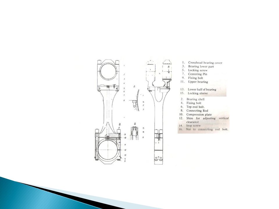
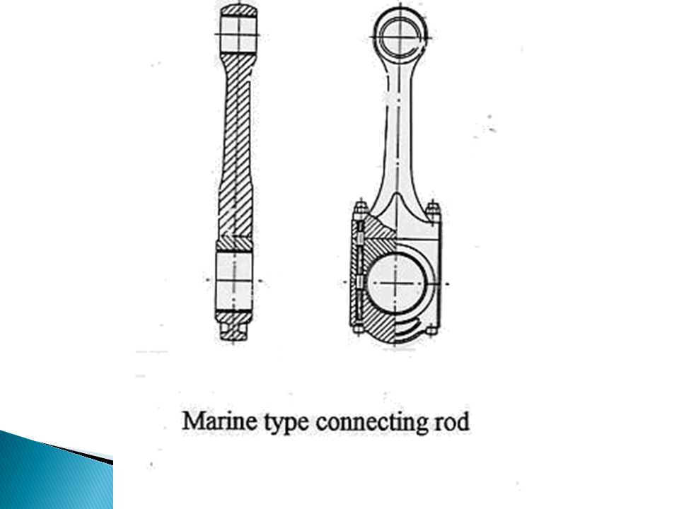
1.DEFINITION * A running component connecting the crankshaft to the piston ( in trunk piston engines ) or to the crosshead ( in crosshead engines ). It has both linear ( reciprocating, up-and-down ) & rotational ( rotary ) motion. 2. FUNCTION Primary function: to transmit the push ( pressure, thrust ) of the piston to the crankshaft, either directly or indirectly. Secondary function: ( in most designs ) to convey cooling oil to the pistons which demands for a quite a large diameter passage 3. TYPES * Marine type: The large end bearing is seperate from rod the rod which has a palm end ( T-shaped end )
 & rotational ( rotary ) motion. 2. FUNCTION Primary function: to transmit the push ( pressure, thrust ) of the piston to the crankshaft, either directly or indirectly. Secondary function: ( in most designs ) to convey cooling oil to the pistons which demands for a quite a large diameter passage 3. TYPES * Marine type: The large end bearing is seperate from rod the rod which has a palm end ( T-shaped end ).")
15
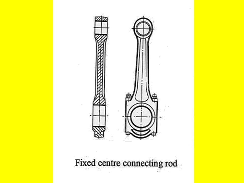
1.DEFINITION * A running component connecting the crankshaft to the piston ( in trunk piston engines ) or to the crosshead ( in crosshead engines ). It has both linear ( reciprocating, up-and-down ) & rotational ( rotary ) motion. 2. FUNCTION Primary function: to transmit the push ( pressure, thrust ) of the piston to the crankshaft, either directly or indirectly. Secondary function: ( in most designs ) to convey cooling oil to the pistons which demands for a quite a large diameter passage 3. TYPES * Marine type: The large end bearing is seperate from rod the rod which has a palm end ( T-shaped end ) Fixed centre design: The upper half of the crankpin box makes part of of the connecting rod./ Alternative design: Connecting rod with obliquely split large end.
 & rotational ( rotary ) motion. 2. FUNCTION Primary function: to transmit the push ( pressure, thrust ) of the piston to the crankshaft, either directly or indirectly. Secondary function: ( in most designs ) to convey cooling oil to the pistons which demands for a quite a large diameter passage 3. TYPES * Marine type: The large end bearing is seperate from rod the rod which has a palm end ( T-shaped end ) Fixed centre design: The upper half of the crankpin box makes part of of the connecting rod./ Alternative design: Connecting rod with obliquely split large end..")
18
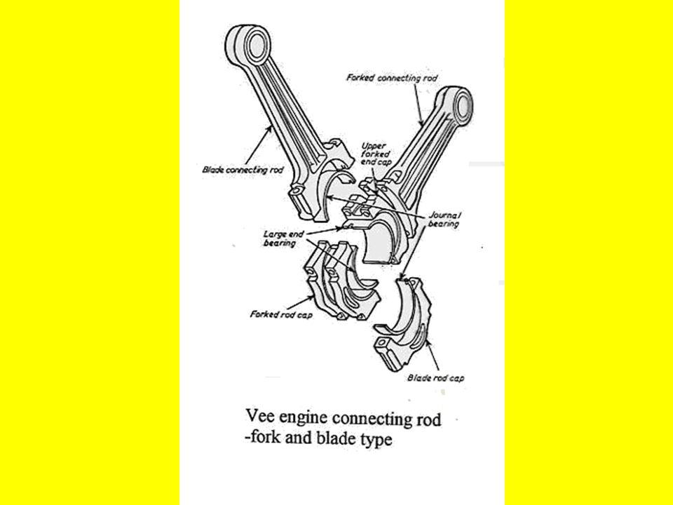
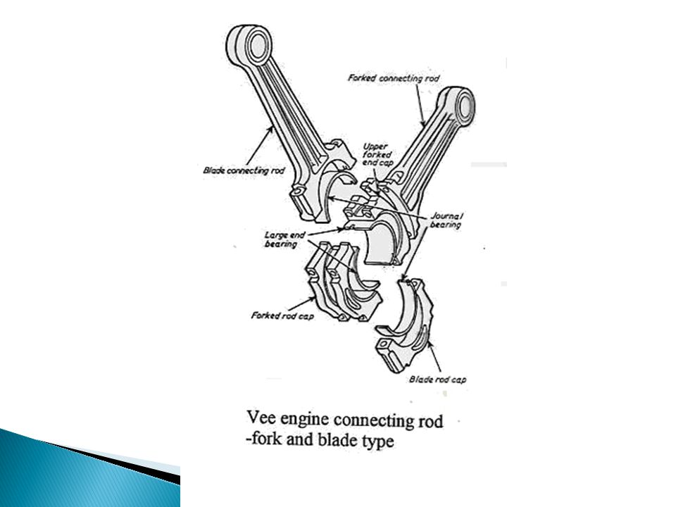
Fork and blade type: Vee engine connecting rods.

20
Articular type: Vee engine connecting rods

22
Fork and blade type: Vee engine connecting rods. Articular type: Vee engine connecting rods 4. ELEMENTS

23
Fork and blade type: Vee engine connecting rods. Articular type: Vee engine connecting rods 4. ELEMENTS 4.1 Crankpin end →

24
Fork and blade type: Vee engine connecting rods. Articular type: Vee engine connecting rods 4. ELEMENTS 4.1 Crankpin end → Bottom end bearing, lower end bearing, big end bearing, crankpin bearing, or large end bearing.

26
Fork and blade type: Vee engine connecting rods. Articular type: Vee engine connecting rods 4. ELEMENTS 4.1 Crankpin end → Bottom end bearing, lower end bearing, big end bearing, crankpin bearing, or large end bearing. Attachment point for the crankpin, carrying a bearing.

27
Fork and blade type: Vee engine connecting rods. Articular type: Vee engine connecting rods 4. ELEMENTS 4.1 Crankpin end → Bottom end bearing, lower end bearing, big end bearing, crankpin bearing, or large end bearing. Attachment point for the crankpin, carrying a bearing. It consists of two half removable shells ( marine type ) held together by bolts and nuts. The shells have a lining of bearing metal, white metal or Babbitt ( copper-lead or tin-aluminium+thin flashing of lead or indium to provide for an anticorrosion layer.
 held together by bolts and nuts. The shells have a lining of bearing metal, white metal or Babbitt ( copper-lead or tin-aluminium+thin flashing of lead or indium to provide for an anticorrosion layer..")
28
Fork and blade type: Vee engine connecting rods. Articular type: Vee engine connecting rods 4. ELEMENTS 4.1 Crankpin end → Bottom end bearing, lower end bearing, big end bearing, crankpin bearing, or large end bearing. Attachment point for the crankpin, carrying a bearing. It consists of two half removable shells ( marine type ) held together by bolts and nuts. The shells have a lining of bearing metal, white metal or Babbitt ( copper-lead or tin-aluminium+thin flashing of lead or indium to provide for an anticorrosion layer. Bearing housing contains cooling oil grooves.
 held together by bolts and nuts. The shells have a lining of bearing metal, white metal or Babbitt ( copper-lead or tin-aluminium+thin flashing of lead or indium to provide for an anticorrosion layer. Bearing housing contains cooling oil grooves..")
29
Fork and blade type: Vee engine connecting rods. Articular type: Vee engine connecting rods 4. ELEMENTS 4.1 Crankpin end → Bottom end bearing, lower end bearing, big end bearing, crankpin bearing, or large end bearing. Attachment point for the crankpin, carrying a bearing. It consists of two half removable shells ( marine type ) held together by bolts and nuts. The shells have a lining of bearing metal, white metal or Babbitt ( copper-lead or tin-aluminium+thin flashing of lead or indium to provide for an anticorrosion layer. Bearing housing contains cooling oil grooves. Between the foot and the box ( bearing housing ) there are shims ( distance pieces, compression shims, compression plates ) for adjustment of cylinder compression.
 held together by bolts and nuts. The shells have a lining of bearing metal, white metal or Babbitt ( copper-lead or tin-aluminium+thin flashing of lead or indium to provide for an anticorrosion layer. Bearing housing contains cooling oil grooves. Between the foot and the box ( bearing housing ) there are shims ( distance pieces, compression shims, compression plates ) for adjustment of cylinder compression..")
30
4.2 Rod shank

31
It is also called the body and may take up different forms. It has d driling throughout its lenght.

33
4.2 Rod shank It is also called the body and may take up different forms. It has d driling throughout its lenght. 4.3 Gudgeon pin end →

34
4.2 Rod shank It is also called the body and may take up different forms. It has d driling throughout its lenght. 4.3 Gudgeon pin end → Upper end bearing, top end bearing, or small end bearing, wristpin bearing.

35
4.2 Rod shank It is also called the body and may take up different forms. It has d driling throughout its lenght. 4.3 Gudgeon pin end → Upper end bearing, top end bearing, or small end bearing, wristpin bearing. Upper end bearing is a bushing having an interference fit ( nip ) in the eye bored in the rod.
 in the eye bored in the rod..")
37
4.2 Rod shank It is also called the body and may take up different forms. It has d driling throughout its lenght. 4.3 Gudgeon pin end → Upper end bearing, top end bearing, or small end bearing, wristpin bearing. Upper end bearing is a bushing having an interference fit ( nip ) in the eye bored in the rod. The eye is a single piece bearing ( bush, bushing ) pressed into sleeve.
 in the eye bored in the rod. The eye is a single piece bearing ( bush, bushing ) pressed into sleeve..")
38
4.2 Rod shank It is also called the body and may take up different forms. It has d driling throughout its lenght. 4.3 Gudgeon pin end → Upper end bearing, top end bearing, or small end bearing, wristpin bearing. Upper end bearing is a bushing having an interference fit ( nip ) in the eye bored in the rod. The eye is a single piece bearing ( bush, bushing ) pressed into sleeve. The bushing is of bronze or of cast steel & centrifugally cast bearing metal.
 in the eye bored in the rod. The eye is a single piece bearing ( bush, bushing ) pressed into sleeve. The bushing is of bronze or of cast steel & centrifugally cast bearing metal..")
39
5. STRESSES

40
5.1 Axial forces →

41
5. STRESSES 5.1 Axial forces → resulting from gas pressure and inertia of piston assembly modified by the side thrust arrising in consequence of the connecting rod crank angle. The maximum axial load is compressive ( at TDC ).
..")
42
5. STRESSES 5.1 Axial forces → resulting from gas pressure and inertia of piston assembly modified by the side thrust arrising in consequence of the connecting rod crank angle. The maximum axial load is compressive ( at TDC ). Tensile stresses occur after firing, due to piston inertia.
. Tensile stresses occur after firing, due to piston inertia..")
43
5. STRESSES 5.1 Axial forces → resulting from gas pressure and inertia of piston assembly modified by the side thrust arrising in consequence of the connecting rod crank angle. The maximum axial load is compressive ( at TDC ). Tensile stresses occur after firing, due to piston inertia. Bending stresses also occur after firing.
. Tensile stresses occur after firing, due to piston inertia. Bending stresses also occur after firing..")
44
5. STRESSES 5.1 Axial forces → resulting from gas pressure and inertia of piston assembly modified by the side thrust arrising in consequence of the connecting rod crank angle. The maximum axial load is compressive ( at TDC ). Tensile stresses occur after firing, due to piston inertia. Bending stresses also occur after firing. 5.2 Transverse forces →
. Tensile stresses occur after firing, due to piston inertia. Bending stresses also occur after firing. 5.2 Transverse forces →.")
45
5. STRESSES 5.1 Axial forces → resulting from gas pressure and inertia of piston assembly modified by the side thrust arrising in consequence of the connecting rod crank angle. The maximum axial load is compressive ( at TDC ). Tensile stresses occur after firing, due to piston inertia. Bending stresses also occur after firing. 5.2 Transverse forces → known as whip, are caused by inertia effects of the rod mass. Fortunatly axial & transverse forces do not occur at the same time.
. Tensile stresses occur after firing, due to piston inertia. Bending stresses also occur after firing. 5.2 Transverse forces → known as whip, are caused by inertia effects of the rod mass. Fortunatly axial & transverse forces do not occur at the same time..")
46
5. STRESSES 5.1 Axial forces → resulting from gas pressure and inertia of piston assembly modified by the side thrust arrising in consequence of the connecting rod crank angle. The maximum axial load is compressive ( at TDC ). Tensile stresses occur after firing, due to piston inertia. Bending stresses also occur after firing. 5.2 Transverse forces → known as whip, are caused by inertia effects of the rod mass. Fortunatly axial & transverse forces do not occur at the same time. 6. LUBRICATION
. Tensile stresses occur after firing, due to piston inertia. Bending stresses also occur after firing. 5.2 Transverse forces → known as whip, are caused by inertia effects of the rod mass. Fortunatly axial & transverse forces do not occur at the same time. 6. LUBRICATION.")
47
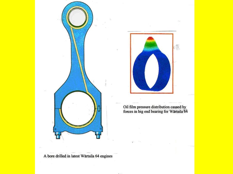
5. STRESSES 5.1 Axial forces → resulting from gas pressure and inertia of piston assembly modified by the side thrust arrising in consequence of the connecting rod crank angle. The maximum axial load is compressive ( at TDC ). Tensile stresses occur after firing, due to piston inertia. Bending stresses also occur after firing. 5.2 Transverse forces → known as whip, are caused by inertia effects of the rod mass. Fortunatly axial & transverse forces do not occur at the same time. 6. LUBRICATION It is carried out through the shank bore ( drilling ) in running throughout the shank lenght. It conducts oil from the big end to the small end for lubrication and to the inside of piston for its cooling.
. Tensile stresses occur after firing, due to piston inertia. Bending stresses also occur after firing. 5.2 Transverse forces → known as whip, are caused by inertia effects of the rod mass. Fortunatly axial & transverse forces do not occur at the same time. 6. LUBRICATION It is carried out through the shank bore ( drilling ) in running throughout the shank lenght. It conducts oil from the big end to the small end for lubrication and to the inside of piston for its cooling..")
50
7. WITHDRAWAL

51
( Pulling out, removal ) In most desings through the upper end. In few desigms the piston and The connecting rod are withdrawn downwards.

55
CONNECTING RODS (text)
")
57
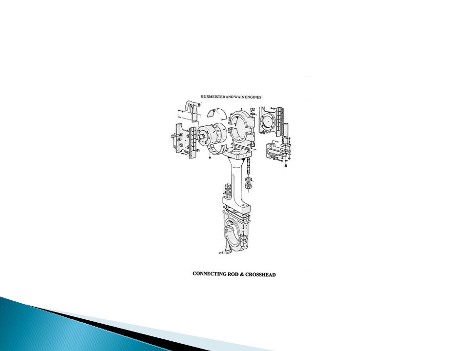
The connecting rod does this important task of converting reciprocating motion of the piston into rotary motion of the crankshaft. It consists of an upper forked section which fits on the crosshead bearings while the lower part fits on the crankpin bearing.

59
The connecting rod does the important task of.......... It consists of an upper forked section which fits on.......... while the lower part fits on...........

60
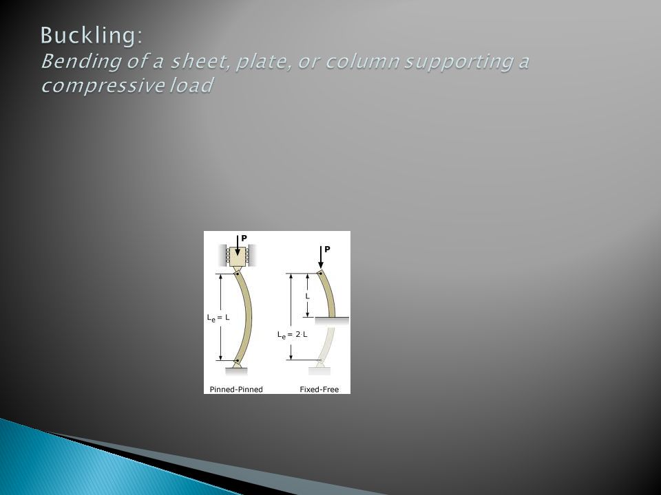
With this sort of arrangement there is heavy axial loading on the connecting rod which reaches its peak at the top dead center because the gas pressure and the inertial forces add to increase the overall force. Other abnormal working conditions such as piston seizure and momentary increase in peak pressure can also result in severe increase in stress on the con- rod and it could fail due to buckling due to these forces. Buckle: to bend or cause to bend out of shape, esp. as a result of pressure or heat Buckling: deformacija, izvijanje, (lima, stupa itd. pod tlakom)
.")
62
With this sort of arrangement there is heavy __________ on the connecting rod which reaches its peak at the __________ because the gas pressure and the inertial forces add to increase the overall force. Other abnormal working conditions such as __________ and momentary increase in peak pressure can also result in severe increase in stress on the con-rod and it could fail due to __________ due to these forces. Buckling: Bending of a sheet, plate, or column supporting a compressive load.

63
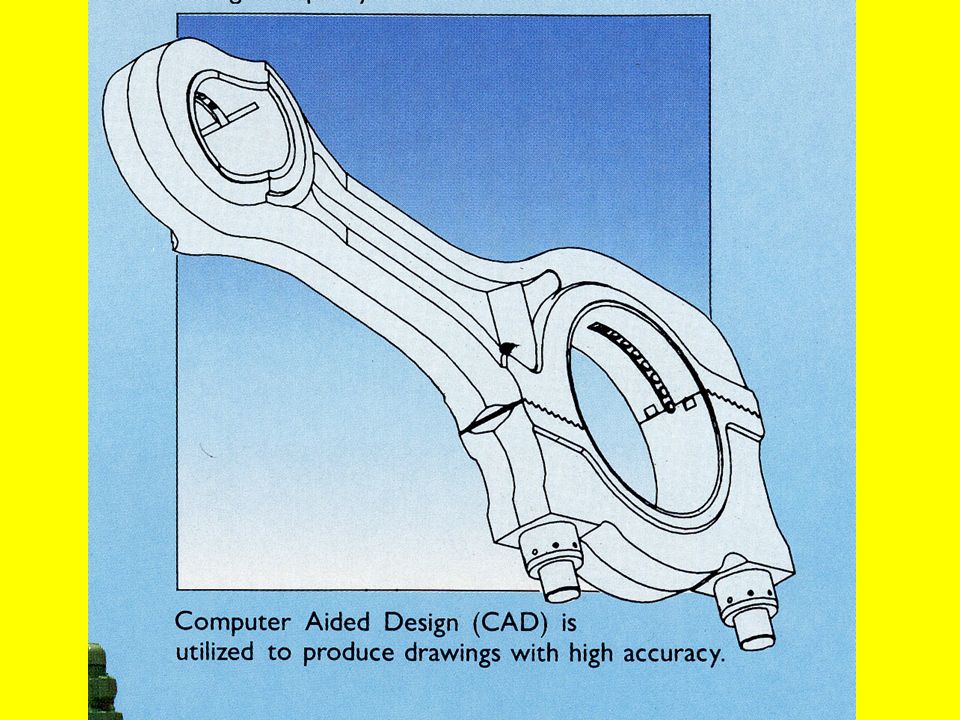
Normally connecting rods are forge- manufactured and the material used is typically mild and medium carbon steel. The ends where the rod is connected to the X-head or crankpin have bearings which are made of white metal working surface and shims (thing packings) are used to make the necessary adjustments. There are four bolts at each connection point which help for assembly and removal of the connecting rod, and are tightened to their required torque using hydraulic jack.
 are used to make the necessary adjustments. There are four bolts at each connection point which help for assembly and removal of the connecting rod, and are tightened to their required torque using hydraulic jack..")
64
Normally connecting rods are forge- manufactured and the material used is typically mild and medium carbon _______. The ends where the rod is connected to the X- head or crankpin have bearings which are made of _______ metal working surface and shims (thing packings) are used to make the necessary _________. There are four _______ at each connection point which help for assembly and _________ of the connecting rod, and are tightened to their required __________ using hydraulic jack.
 are used to make the necessary _________. There are four _______ at each connection point which help for assembly and _________ of the connecting rod, and are tightened to their required __________ using hydraulic jack..")
65
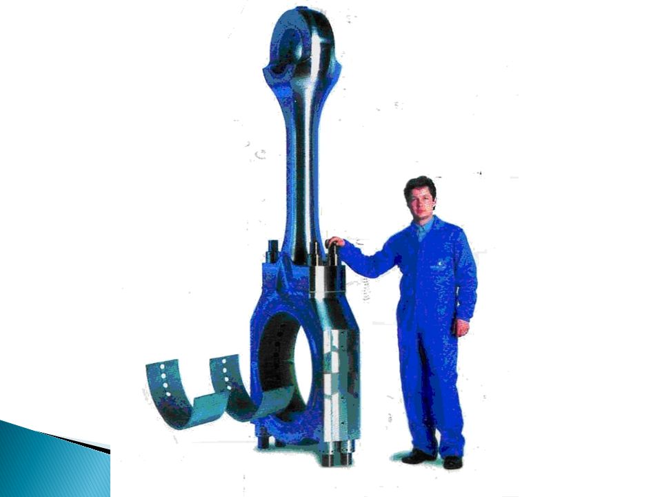
In case of auxiliary marine diesel engines which are 4-stroke engines, the con-rod is constructed by drop forging and the material used is normally alloy steel and the alloy metals being nickel, chromium and molybdenum. The bottom end connecting bolts of 4 stroke engines often fail due to severe forces acting on them and this failure in turn can cause various structural damages in the engine in turn. Hence it is very necessary to tighten these bolts properly and keep checking for their tightness, lest one has to pay a heavy price for this minor negligence later on.

66
___ case ___ auxiliary marine diesel engines which are 4-stroke engines, the con-rod is constructed ___ drop forging and the material used is normally alloy steel and the alloy metals being nickel, chromium and molybdenum. The bottom end connecting bolts ___ 4 stroke engines often fail due ___ severe forces acting ___ them and this failure ___ turn can cause various structural damages ___ the engine in turn. Hence it is very necessary ___ tighten these bolts properly and keep checking ___ their tightness, lest one has ___ pay a heavy price ___ this minor negligence later ___.

67
The connecting rod connects the crankshaft directly to the piston or, as in some other designs, to the crosshead. It is a running component connecting the crankshaft to the piston (in trunk piston engines) or to the crosshead (in crosshead engines). It has both linear (reciprocating, up-and-down) & rotational (rotary) motion.
 or to the crosshead (in crosshead engines). It has both linear (reciprocating, up-and-down) & rotational (rotary) motion..")
68
The connecting rod connects the crankshaft directly.............. or, as in some other designs, to............. It connects the crankshaft to the piston (in _____ piston engines) or to the crosshead (in _____ engines). It has two motions: ________ (reciprocating, up-and-down) & ___________ motion.
 or to the crosshead (in _____ engines). It has two motions: ________ (reciprocating, up-and-down) & ___________ motion..")
69
The primary function of the connecting rod is to transmit.........................., either directly or indirectly. Its secondary function is to....................., which demands for a quite a large __________ passage

70
Marine type: The large end bearing is seperate from rod the rod which has a palm end (T-shaped end) Fixed centre design: The upper half of the crankpin box makes part of of the connecting rod. Alternative design: Connecting rod with obliquely split large end. Fork and blade type: Vee engine connecting rods. Articular type: Vee engine connecting rods

71
____________: The large end bearing is seperate from rod the rod which has a palm end (T-shaped end) ____________: The upper half of the crankpin box makes part of of the connecting rod. Alternative design: Connecting rod with obliquely split large end. ___________type: Vee engine connecting rods. _________ type: Vee engine connecting rods

73
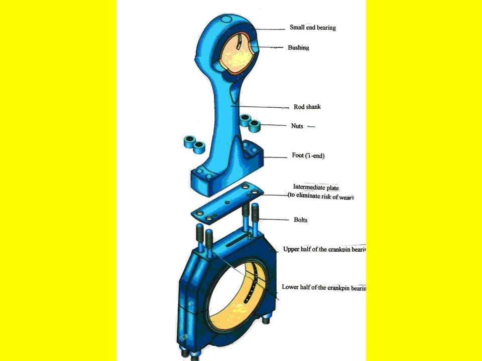
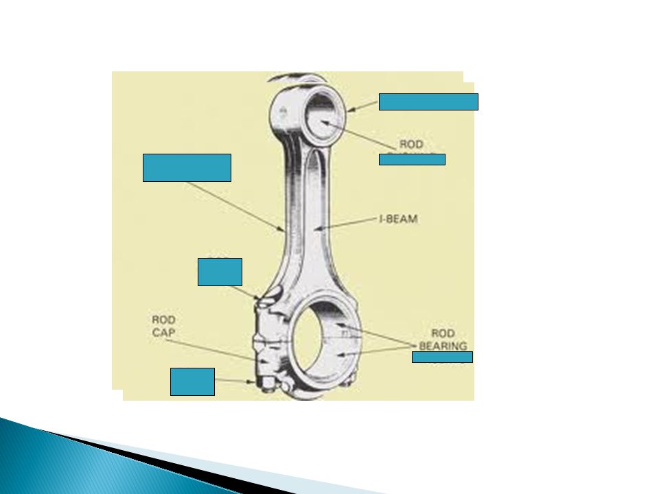
1. Crankpin end → Bottom end bearing, lower end bearing, big end bearing, crankpin bearing, or large end bearing. ◦ Attachment point for the crankpin, carrying a bearing. ◦ It consists of two half removable shells (marine type) held together by bolts and nuts. The shells have a lining of bearing metal, white metal or Babbitt (copper-lead or tin- aluminium+thin flashing of lead or indium to provide for an anticorrosion layer). ◦ Bearing housing contains cooling oil grooves. ◦ Between the foot and the box (bearing housing) there are shims (distance pieces, compression shims, compression plates) for adjustment of cylinder compression.
 held together by bolts and nuts. The shells have a lining of bearing metal, white metal or Babbitt (copper-lead or tin- aluminium+thin flashing of lead or indium to provide for an anticorrosion layer). ◦ Bearing housing contains cooling oil grooves. ◦ Between the foot and the box (bearing housing) there are shims (distance pieces, compression shims, compression plates) for adjustment of cylinder compression..")
74
1. Crankpin end → Bottom end bearing, lower end bearing, big end bearing, crankpin bearing, or large end bearing. ◦ _________ point for the crankpin, carrying a ___________. ◦ It consists of two half removable __________ (marine type) held together by bolts and nuts. The shells have a ________ of bearing metal, ________ metal or Babbitt (copper-lead or tin-aluminium+thin __________ of lead or indium to provide for an anticorrosion layer). ◦ Bearing housing contains cooling oil ____________. ◦ Between the foot and the box (bearing housing) there are ___________ (distance pieces, compression shims, compression plates) for __________ of cylinder compression.
 held together by bolts and nuts. The shells have a ________ of bearing metal, ________ metal or Babbitt (copper-lead or tin-aluminium+thin __________ of lead or indium to provide for an anticorrosion layer). ◦ Bearing housing contains cooling oil ____________. ◦ Between the foot and the box (bearing housing) there are ___________ (distance pieces, compression shims, compression plates) for __________ of cylinder compression..")
77
2. Rod shank It is also called the body and may take up different forms. It has driling throughout its length. 3. Gudgeon pin end → Upper end bearing, top end bearing, or small end bearing, wristpin bearing. Upper end bearing is a bushing having an interference fit (nip) in the eye bored in the rod. The eye is a single piece bearing (bush, bushing) pressed into sleeve.
 in the eye bored in the rod. The eye is a single piece bearing (bush, bushing) pressed into sleeve..")
78
2. Rod shank It is also called the ______ and may take up different forms. It has driling throughout its ________. 3. Gudgeon pin end → Upper end ________, top end bearing, or small end bearing, wristpin bearing. Upper end bearing is a ________ having an interference fit (nip) in the eye bored in the rod. The eye is a single piece bearing (bush, bushing) ___________into sleeve.
 in the eye bored in the rod. The eye is a single piece bearing (bush, bushing) ___________into sleeve..")
80
◦ Gudgeon pin ◦ Rod shank ◦ Small end ◦ Large end ◦ journal

82
1. Axial forces → resulting from gas pressure and inertia of piston assembly modified by the side thrust arrising in consequence of the connecting rod crank angle. The maximum axial load is compressive (at TDC). Tensile stresses occur after firing, due to piston inertia. Bending stresses also occur after firing. 2. Transverse forces → known as whip, are caused by inertia effects of the rod mass. Fortunately, axial & transverse forces do not occur at the same time.
. Tensile stresses occur after firing, due to piston inertia. Bending stresses also occur after firing. 2. Transverse forces → known as whip, are caused by inertia effects of the rod mass. Fortunately, axial & transverse forces do not occur at the same time..")
83
1. Axial forces → ___________ from gas pressure and inertia of piston assembly modified by the side thrust __________ in consequence of the connecting rod crank angle. The maximum axial _____ is compressive (at TDC). T_________ stresses occur after firing, due to piston inertia. B_________ stresses also occur after firing. 2. Transverse forces → known as ________, are caused by _______ effects of the rod mass. Fortunately, axial & transverse forces do not occur...................
. T_________ stresses occur after firing, due to piston inertia. B_________ stresses also occur after firing. 2. Transverse forces → known as ________, are caused by _______ effects of the rod mass. Fortunately, axial & transverse forces do not occur")
84
Lubrication is carried out through the shank bore (drilling) in running throughout the shank length. It conducts oil from the big end to the small end for lubrication and to the inside of piston for its cooling.

85
to shape, cut, or remove (excess material) from (a workpiece) using a machine tool
 from (a workpiece) using a machine tool")
86
Lubrication is carried out through the................(drilling) and............... the shank _______. It conducts oil from the ________ to the ________ for lubrication and to the inside of ________ for its cooling.

87
In essence, the connecting rod is a straight bar with a ______ at each end, whose purpose is to transmit the piston ________ to the crankshaft. The connecting rod must be strong, yet must not be too heavy because of inertia forces, especially in ____ speed engines. Articulated rods are made of _______ pieces.

88
In essence, it is straight bar with a bearing at each end, whose purpose is to transmit the piston thrust to the crankshaft. The connecting rod must be strong, yet must not be too heavy because of inertia forces, especially in high speed engines. Articulated rods are made of two pieces.

89
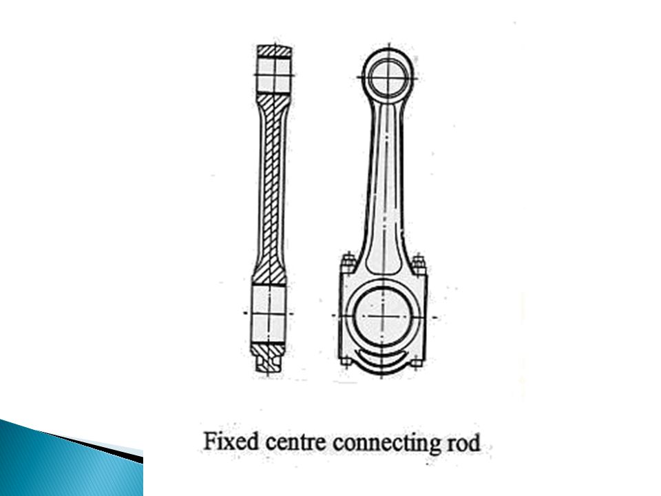
The rod is usually forged from alloy steel, frequently with an “I” or “channel” section to give its greatest stiffness for its weight. Connecting rod large ends are basically either of “marine” type or fixed centre design. These two basic designs are shown in Fig. 3.1 and 3.2.

90
The rod is usually forged from alloy _______, frequently with an “I” or “channel” section to give its greatest stiffness for its weight. Connecting rod large ends are basically either of “_______” type or _______design. These two basic designs are _____ in Fig. 3.1 and 3.2.

92
In the marine type design (Fig.1) the rod large end, called “crankpin end”, consists of a separate bearing housing (or box) divided in two parts, bolted to a foot on the rod shank. A distance piece, known as compression plate or shim, is interposed between the foot and the box to permit the piston to be moved nearer to or farther from the cylinder head at top dead centre. Its thickness is chosen so as to ensure correct compression ratio.

93
In the marine type design (Fig.1) the rod large end, called “crankpin end”, consists of a.................. divided in two parts, bolted to a foot on the rod shank. A distance piece, known as _________ or shim, is interposed between the ________ and the box to ______ the piston to be moved nearer to or farther from the cylinder head at _______. Its thickness is chosen so as to ensure correct compression __________.

95
The simpler construction of the fixed centre rod (Fig.2) does not have this adjustment and relies on accuracy to ensure correct clearances. With a few exceptions medium speed diesel engines have trunk pistons with the result that pistons and connecting rods have to be fitted together before being assembled into the cylinder. The methods of assembly and overhaul tend to influence the design of the large end.

96
The simpler construction of the fixed centre rod (Fig.2) does not have this adjustment and relies on accuracy to..................... With a few exceptions medium speed diesel engines have trunk pistons with the result that pistons and connecting rods have to be fitted together...................... The methods of ________ and _________ tend to influence the design of the large end.

100
For one or two types of engine, the piston and rod can be withdrawn downwards from the cylinder into the crankcase and then out through the crankcase door. However, this design tends to result in a high engine so that the piston and rod is more usually withdrawn upwards. This means that in case of engines having cylinders blocks, the rod has to be small enough to pass through the bore of the cylinder.

101
For one or two types of engine, the piston and rod can be withdrawn ______ from the cylinder into the crankcase and then out.................... However, this design tends to result in............... so that the piston and rod is more usually withdrawn ________. This means that in case of engines having cylinders blocks, the rod has to be small enough.............................

104
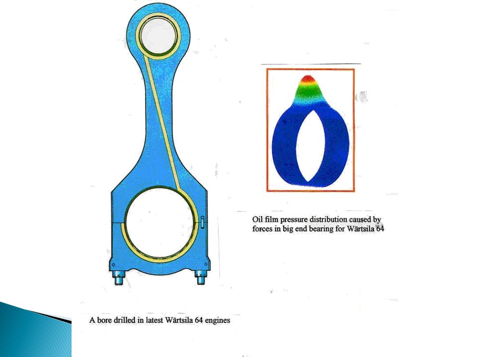
The design of the large end bearing is similar to that of the main bearing. The steel shells, of relatively thin wall section, have a lining of bearing metal, white metal, copper-lead or tin-aluminium, and a thin flashing of lead or indium to provide an anti-corrosion layer. In the bearing housing there are grooves through which oil passes to cool the piston.

105
The design of the large end bearing is similar to that of the ________ bearing. The steel shells, of relatively thin wall section, have a ________ of bearing metal, white metal, copper-lead or tin-aluminium, and a thin ________ of lead or indium to provide an anti-corrosion ______. In the bearing housing there are ___________ through which oil passes to cool the __________.

107
The small (top) end bearing is a bush having an interference fit in the eye bored in the rod. The bushing may be of bronze or other hard bearing metal or it can be a composite structure of steel with a bearing metal lining. The shank of the rod usually has a bore throughout its length which conducts oil from the large end to the small end for lubrication and to the inside of the piston for cooling.

110
1. What is the function of the connecting rod? What does it consists of? 2. What are the forces (stresses) acting on the connecting rod of a single acting engine? 3. State the difference between the “connecting rod “ and “piston rod”. 4. When are the pistons and connecting rods fitted together? 5. Describe the two ways of removing the connecting rod from the cylinder. 6. What is the requirement for the connecting rods in the engines having cylinder blocks? 7. What are the main parts of a bearing? 8. What are the bearing shells made of? 9. What is a joined by the large and the small end bearings? 10. When is the engine fitted with a crosshead? 11. How are the large end and small end bearings lubricated?
 acting on the connecting rod of a single acting engine. 3. State the difference between the connecting rod and piston rod . 4. When are the pistons and connecting rods fitted together. 5. Describe the two ways of removing the connecting rod from the cylinder. 6. What is the requirement for the connecting rods in the engines having cylinder blocks. 7. What are the main parts of a bearing. 8. What are the bearing shells made of. 9. What is a joined by the large and the small end bearings. 10. When is the engine fitted with a crosshead. 11. How are the large end and small end bearings lubricated .")
111
CRANKSHAFT, MAIN BEARINGS AND SHAFT ALINGNMENT

112
The crankshaft, which converts the _________ motion of the piston to rotating motion, must resist the _________ stresses caused by the connecting rod _________ when the piston is at top centre. Then the maximum gas pressure acts straight down on the _________ and tends to bend the shaft between the adjacent _________. The crankshaft must also _________ the torsional forces produced by the change of speed. Medium speed engines have crankshaft usually solid _________, i.e. made from a single piece, while slow speed engine crankshafts are mostly of semi-built design with crankpins and _________ forged or cast in one piece and shrunk on to the _________. The type of steel used, which is carbon or alloy steel containing nickel, chromium and molybdenum, is chosen for its strength, resistance to _________ and hardness of bearing surface.

113
The cranks of a multi-throw shaft are set at appropriate angles giving a “firing order” for the engine. The firing order is chosen primarily to obtain a smooth torque and the best mechanical balance. However, main bearings loads, exhaust arrangements suitable for turbocharging and torsional vibration may also be taken into account. Although the crankshaft appears to be robust, they rely on the main bearings to develop their full strength. When a crankshaft has to be handled outside the engine, it should be carefully supported to avoid high bending moments on it by its own weight. In the engine it is essential to ensure that the bearings carrying it are in good alignment, as bearing misalignment will cause the crankshaft to bend and eventually break it. The main bearing shells are made of steel with a lining of bearing metal which can be white metal, copper-lead or aluminium-tin alloy. A thin flash of lead or indium is often added to provide a layer giving protection against corrosion. The shells are held in position and shape by seatings of the bedplate or frame.To ensure efficient and reliable operation the crankshaft should be checked periodically for alignment by measuring the deflection of the webs.

Similar presentations


 Design>")


>")


 or to the crosshead.>")