Download presentation
Presentation is loading. Please wait.

1
The New CT and MR DICOM Objects: Why All the Fuss? Brad Erickson David Clunie

2
Disclosures Bradley J Erickson, MD PhD Member, Siemens Medical Advisory Board David Clunie, MBBS CTO, RadPharm (Princeton Radiology Pharmaceutical Research) PixelMed Publishing - contractor for the NEMA Enhanced CT and MR test tools and images
 PixelMed Publishing - contractor for the NEMA Enhanced CT and MR test tools and images")
3
Acknowledgments Kees Verduin, Philips Medical Systems Robert Haworth, GE Healthcare Charles Parisot, GE Healthcare Bernhard Hassold, Siemens Medical Solutions

4
A Brief History of DICOM Early imaging devices created images in a vendor-proprietary format. Needed a common medical image format that would allow transfer of image data to workstations. That led to ACR-NEMA 1.0.

5
DICOM Through the Decades DICOM working groups have made significant improvements and extensions to the original specification. Network protocols Media DICOM-SR Hanging Protocols CAD support

6
But DICOM isn’t perfect

7
And even if it was, imaging changes…

8
Problem: Important data elements are not standard New pulse sequences have developed since DICOM (e.g. diffusion, perfusion, new CT scanning modes). I can’t process or display these well across vendor systems.
. I can’t process or display these well across vendor systems..")
9
Problem 1: Data Handling We routinely acquire perfusion images on all patients with brain tumors. If we archive the computed images, what happens if the software changes? Therefore, we archive the raw data and computed images. But can new software ‘understand’ those older images to make valid comparisons?

10
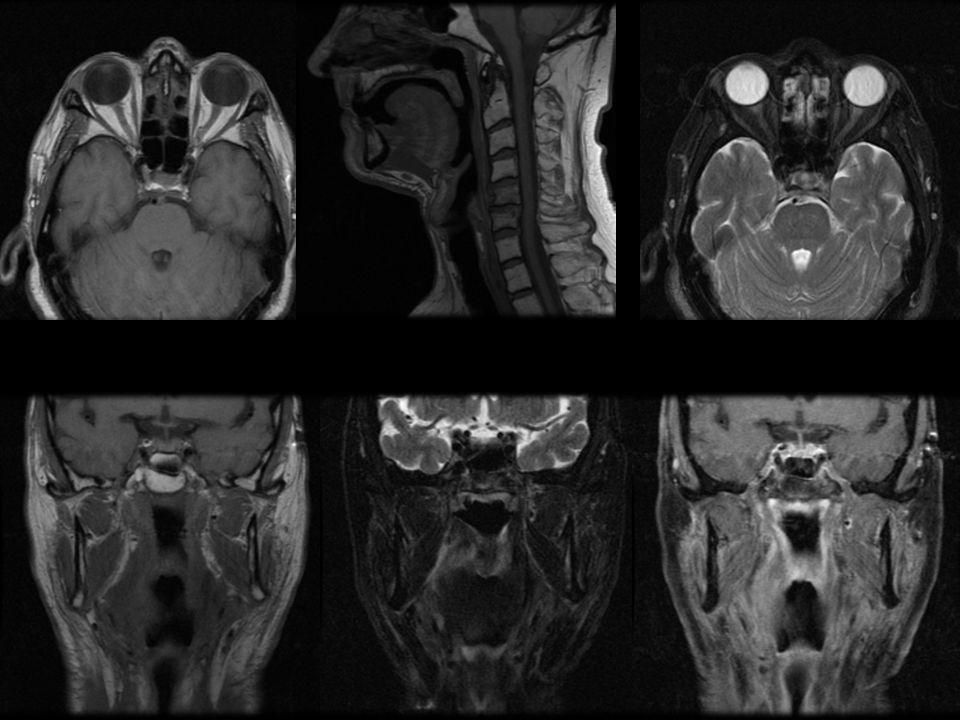
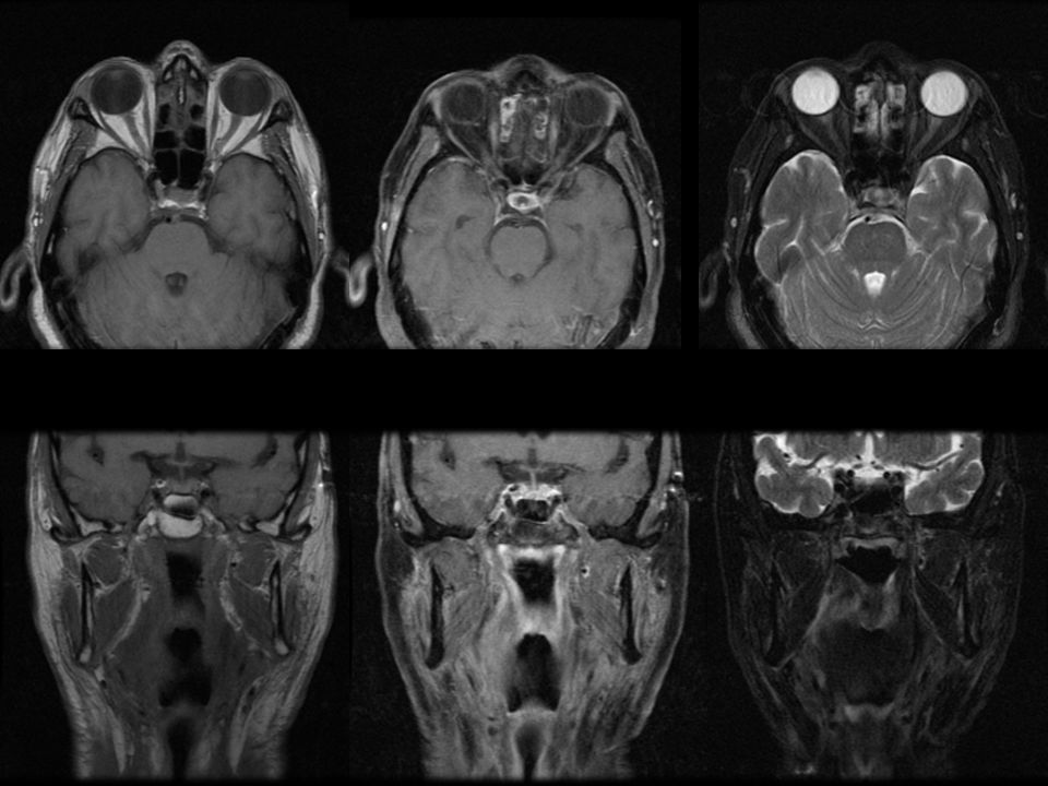
Problem 2: Hanging Protocols My PACS uses the series # to determine where to hang a series. This doesn’t reflect the complexity of my practice. (e.g. motion throws off #’s) If all these new data fields are available, why can’t the workstation compute the image type (e.g. “T1 sagittal”, “T2 axial”) and hang it where I want it? (I want Post in the middle, and the Pre and T2 on either side)
 If all these new data fields are available, why can’t the workstation compute the image type (e.g. T1 sagittal , T2 axial ) and hang it where I want it. (I want Post in the middle, and the Pre and T2 on either side).")
13
Organization of CT & MR Images Original objects Series organization + a few attributes + terms Enhanced objects Multiple frames in a single object Many more standard mandatory attributes Many more standard terms Enables Greater interoperability of applications More effective hanging protocols Reduced dependence on private attributes

14
Technique Attributes & Terms CTMR SOP Class OriginalEnhancedOriginalEnhanced Attributes (Mandatory) 18 (0)41 (39)44 (2)103 (94) Terms (Enumerated) 4 (2)86 (18)38 (9)228 (47)
 18 (0)41 (39)44 (2)103 (94) Terms (Enumerated) 4 (2)86 (18)38 (9)228 (47)")
15
CT Image Type Value 3 Original SOP Classes AXIAL or LOCALIZER Enhanced SOP Classes Common to CT and MR ANGIO, FLUOROSCOPY, LOCALIZER, MOTION, PERFUSION, PRE_CONTRAST, POST_CONTRAST, REST, STRESS, VOLUME CT-specific ATTENUATION, CARDIAC, CARDIAC_GATED, REFERENCE

16
MR Acquisition Contrast Original SOP Classes Guess from echo and repetition time, etc. Enhanced SOP Classes New mandatory frame level attribute Acquisition Contrast DIFFUSION, FLOW_ENCODED, FLUID_ATTENUATED, PERFUSION, PROTON_DENSITY, STIR, TAGGING, T1, T2, T2_STAR, TOF, UNKNOWN

17
Geometry unchanged Same as original SOP Classes Image Position and Orientation (Patient) Still need to compute AXIAL, SAGITTAL or CORONAL from orientation vector Still need to compute edge labels (A/P etc) from orientation vector May still need to compare orientation vectors to determine if slices are parallel - stacks will be discussed later
 Still need to compute AXIAL, SAGITTAL or CORONAL from orientation vector Still need to compute edge labels (A/P etc) from orientation vector May still need to compare orientation vectors to determine if slices are parallel - stacks will be discussed later")
18
Enhanced Contrast/Bolus Original SOP Classes Plain text description Difficult to determine presence/absence E.g., description value of “None” Single agent (did not distinguish oral/iv) Codes optional and never used Enhanced SOP Classes Mandatory codes only Multiple items with separate coded routes & timing Presence or absence per-frame can be described
 Codes optional and never used Enhanced SOP Classes Mandatory codes only Multiple items with separate coded routes & timing Presence or absence per-frame can be described")
19
Coded anatomic regions Original SOP Classes Incomplete list of optional defined terms Optional laterality Enhanced SOP Classes Mandatory coded anatomic region Comprehensive & appropriate list of codes Mandatory laterality Per-frame or for entire object

20
T1 SAG PRE GD Hanging protocol rule impact T1 AXIAL PRE GD T2 AXIAL T1 AXIAL POST GD

21
T1 SAG PRE GD Hanging protocol rule impact T1 AXIAL PRE GD T2 AXIAL T1 AXIAL POST GD Acquisition Contrast = T1

22
T1 SAG PRE GD Hanging protocol rule impact T1 AXIAL PRE GD T2 AXIAL T1 AXIAL POST GD Acquisition Contrast = T1

23
T1 SAG PRE GD Hanging protocol rule impact T1 AXIAL PRE GD T2 AXIAL T1 AXIAL POST GD Acquisition Contrast = T1 Image Orientation ≈ 0\1\0\0\0\-1

24
T1 SAG PRE GD Hanging protocol rule impact T1 AXIAL PRE GD T2 AXIAL T1 AXIAL POST GD Acquisition Contrast = T1 Image Orientation ≈ 0\1\0\0\0\-1

25
T1 SAG PRE GD Hanging protocol rule impact T1 AXIAL PRE GD T2 AXIAL T1 AXIAL POST GD Acquisition Contrast = T1 Image Orientation ≈ 0\1\0\0\0\-1 Contrast Agent #1 Administered = NO Route = (G-D101,SNM3, “IV”) Ingredient = (C-17800,SRT, “Gd”)
 Ingredient = (C-17800,SRT, Gd )")
26
T1 SAG PRE GD Hanging protocol rule impact T1 AXIAL PRE GD T2 AXIAL T1 AXIAL POST GD Acquisition Contrast = T1 Image Orientation ≈ 0\1\0\0\0\-1 Contrast Agent #1 Administered = NO Route = (G-D101,SNM3, “IV”) Ingredient = (C-17800,SRT, “Gd”)
 Ingredient = (C-17800,SRT, Gd )")
27
T1 SAG PRE GD Hanging protocol rule impact T1 AXIAL PRE GD T2 AXIAL T1 AXIAL POST GD Acquisition Contrast = T1 Image Orientation ≈ 1\0\0\0\1\0 Contrast Agent #1 Administered = NO Route = (G-D101,SNM3, “IV”) Ingredient = (C-17800,SRT, “Gd”)
 Ingredient = (C-17800,SRT, Gd )")
28
T1 SAG PRE GD Hanging protocol rule impact T1 AXIAL PRE GD T2 AXIAL T1 AXIAL POST GD Acquisition Contrast = T1 Image Orientation ≈ 1\0\0\0\1\0 Contrast Agent #1 Administered = NO Route = (G-D101,SNM3, “IV”) Ingredient = (C-17800,SRT, “Gd”)
 Ingredient = (C-17800,SRT, Gd )")
29
T1 SAG PRE GD Hanging protocol rule impact T1 AXIAL PRE GD T2 AXIAL T1 AXIAL POST GD Acquisition Contrast = T1 Image Orientation ≈ 1\0\0\0\1\0 Contrast Agent #1 Administered = NO Route = (G-D101,SNM3, “IV”) Ingredient = (C-17800,SRT, “Gd”)
 Ingredient = (C-17800,SRT, Gd )")
30
T1 SAG PRE GD Hanging protocol rule impact T1 AXIAL PRE GD T2 AXIAL T1 AXIAL POST GD Acquisition Contrast = T2 Image Orientation ≈ 1\0\0\0\1\0

31
T1 SAG PRE GD Hanging protocol rule impact T1 AXIAL PRE GD T2 AXIAL T1 AXIAL POST GD Acquisition Contrast = T2 Image Orientation ≈ 1\0\0\0\1\0

32
T1 SAG PRE GD Hanging protocol rule impact T1 AXIAL PRE GD T2 AXIAL T1 AXIAL POST GD Acquisition Contrast = T2 Image Orientation ≈ 1\0\0\0\1\0

33
T1 SAG PRE GD Hanging protocol rule impact T1 AXIAL PRE GD T2 AXIAL T1 AXIAL POST GD Acquisition Contrast = T1 Image Orientation ≈ 1\0\0\0\1\0 Contrast Agent #1 Administered = YES Route = (G-D101,SNM3, “IV”) Ingredient = (C-17800,SRT, “Gd”)
 Ingredient = (C-17800,SRT, Gd )")
34
T1 SAG PRE GD Hanging protocol rule impact T1 AXIAL PRE GD T2 AXIAL T1 AXIAL POST GD Acquisition Contrast = T1 Image Orientation ≈ 1\0\0\0\1\0 Contrast Agent #1 Administered = YES Route = (G-D101,SNM3, “IV”) Ingredient = (C-17800,SRT, “Gd”)
 Ingredient = (C-17800,SRT, Gd )")
35
T1 SAG PRE GD Hanging protocol rule impact T1 AXIAL PRE GD T2 AXIAL T1 AXIAL POST GD

36
T1 SAG PRE GD Hanging protocol rule impact T1 AXIAL PRE GD T2 AXIAL T1 AXIAL POST GD Same rules, independent of whether: one single multi-frame image one multi-frame image per acquisition one slice per single frame image one series or multiple

37
Hanging protocol support A productivity advantage of the CT and MR objects Should not have to tailor hanging protocol rules to specific vendors or devices or versions Reliable and standard information Mandatory and standard places (attributes) Mandatory and standard values As technology evolves, yet more standard values will be added to the standard Eliminate dependence on site configured Series Number or Description, whether from acquisition protocol or entered by operator
 Mandatory and standard values As technology evolves, yet more standard values will be added to the standard Eliminate dependence on site configured Series Number or Description, whether from acquisition protocol or entered by operator")
38
DICOM Hanging Protocols Foregoing describes how to use attributes in Enhanced CT and MR objects to improve any hanging protocol engine, including proprietary software DICOM also has recently defined Hanging Protocol SOP Classes To store hanging protocol rules centrally and exchange them between different systems Not a pre-requisite for making use of the enhanced image objects to improve hanging

39
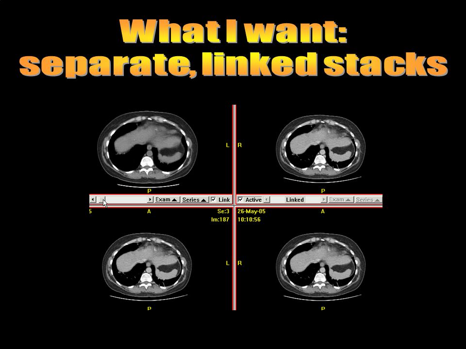
More Hanging Protocol Problems We often do multi-phase CT exams. The hanging protocol should “automagically” hang the pre-contrast, arterial phase, venous phase, late phase in separate stacks.

40
*Courtesy B Bartholmai

41
Current—Vendor X—all post-contrast in 1 series

43
Hanging Protocols We have routine scanning protocols. For these, I don’t want to see the parameters. But for cases where the tech had to do something non-standard, (e.g. flip from prone to supine) I want that to stand out.
 I want that to stand out..")
44
Jane Doe 19 May 05 1-345-989 16:32:12 R Supine

45
Problem: 3D We want to fuse PET images with CT and MR images (from different vendors). We also want to record the alignment solution for future use.

47
Beyond simple image display Visualization Temporal change Short term Long term Quantitation and Analysis

48
Visualization MPR 3D surface and volume rendering MIP for angiography

49
Temporal change Short term Perfusion Cardiac cycle Long term Change between studies

50
Quantitation and analysis Processing of multiple frames Measurement of morphology Linear distance Volumetrics Measurement of physiology and function Perfusion and diffusion fMRI Registration between acquisitions, studies & modalities

51
Supporting advanced applications Original SOP Classes Minimal standard acquisition information Imprecisely defined timing information No organizational structures except Series Quantitation mixed with grayscale pipeline Enhanced SOP Classes Detailed descriptions of advanced acquisition protocols Accurate and well-defined timing information Pre-defined organizational structures Quantitative values and color support

52
Enhanced MR SOP Class attribute types Separate gradient and RF echo train lengths Out-of-plane phase encoding steps Flow compensation Spectrally selective excitation & suppression Blood signal nulling Tagging Diffusion values and direction Spatial saturation slabs Velocity encoding Chemical shift imaging (metabolite maps)
")
53
Enhanced CT SOP Class attribute types Acquisition type Constant volume and fluoroscopy Single and total collimation width (for multiple detectors) Table speed, feed and spiral pitch factor Reconstruction geometry and convolution kernel Exposure information, dose savings and CTDI Vol
 Table speed, feed and spiral pitch factor Reconstruction geometry and convolution kernel Exposure information, dose savings and CTDI Vol")
54
Timing information Original SOP Classes Inconsistent use of Content (Image) and Acquisition Time Contrast timing information never used Enhanced SOP Classes Unambiguous definition of acquisition timing Explicit relationships with contrast & cardiac timing
 and Acquisition Time Contrast timing information never used Enhanced SOP Classes Unambiguous definition of acquisition timing Explicit relationships with contrast & cardiac timing")
55
Timing information

57
Contrast timing Numeric - Administration Profile Allows for multiple contrast agents and phases Volume, start/stop times, rates and duration Categorical Can be specified on a per-frame basis Administered - YES/NO Detected - YES/NO Phase - PRE_CONTRAST, POST_CONTRAST, IMMEDIATE, DYNAMIC, STEADY_STATE, DELAYED, ARTERIAL, CAPILLARY, VENOUS, PORTAL_VENOUS

58
Contrast timing - phase for hanging protocols

59
Organizational Features Multi-frame pixel data Shared and per-frame functional groups Each functional group contains attributes that likely vary as a group, e.g. Pixel Measures, Plane Orientation, Velocity Encoding, etc. Compact & makes explicit what doesn’t change Dimensions a priori hints as to how the frames are organized Specify intended order of traversal, such as space, then time (e.g., for cardiac cine loops) Stacks Groups of spatially-related slices, repeatable Temporal positions
 Stacks Groups of spatially-related slices, repeatable Temporal positions.")
60
Organization of Data Goal is to reduce the work that the receiving application has to do to “figure out” How the data is organized Why it is organized that way Without preventing use of the data in unanticipated ways E.g. 3D on a dataset not intended as a volume Two levels The detailed shared & per-frame attributes The overall dimensions, stacks and temporal positions

61
Per-frame attributes Pixel data Shared attributes Multi-frame Functional Groups

62
Stacks

63
5 Stack ID In-Stack Position 1 3 4 1234 2 5

64
Space 5 In-Stack Position Stack ID = 1 4 3 2 1 Start with a dimension of space. A set of contiguous slices through the heart. Dimensions

65
Temporal Position Index 2 1 Trigger Delay Time 48 ms 0 ms Space Time 5 In-Stack Position Stack ID = 1 4 3 2 1 5 In-Stack Position Stack ID = 1 4 3 2 1 Add dimension of time (delay time from R-wave). Sets of contiguous slices throughout cardiac cycle.

66
Temporal Position Index 2 1 Trigger Delay Time 48 ms 0 ms Space (1) Time (2) 1 \ 5 \ 2 Dimension Index Values Dimension Index Pointers: 1.Stack ID 2.In-Stack Position 3.Temporal Position Index 5 In-Stack Position Stack ID = 1 4 3 2 1 5 In-Stack Position Stack ID = 1 4 3 2 1
 Time (2) 1 \ 5 \ 2 Dimension Index Values Dimension Index Pointers: 1.Stack ID 2.In-Stack Position 3.Temporal Position Index 5 In-Stack Position Stack ID = In-Stack Position Stack ID =")
67
Temporal Position Index 2 1 Trigger Delay Time 48 ms 0 ms Space (1) Time (2) 1 \ 5 \ 2 Dimension Index Values Dimension Index Pointers: 1.Stack ID 2.In-Stack Position 3.Temporal Position Index 5 1\5\1 In-Stack Position Stack ID = 1 4 1\4\1 3 1\3\1 2 1\2\1 1 1\1\1 5 1\5\2 In-Stack Position Stack ID = 1 4 1\4\2 3 1\3\2 2 1\2\2 1 1\1\2
 Time (2) 1 \ 5 \ 2 Dimension Index Values Dimension Index Pointers: 1.Stack ID 2.In-Stack Position 3.Temporal Position Index 5 1\5\1 In-Stack Position Stack ID = 1 4 1\4\1 3 1\3\1 2 1\2\1 1 1\1\1 5 1\5\2 In-Stack Position Stack ID = 1 4 1\4\2 3 1\3\2 2 1\2\2 1 1\1\2")
68
Temporal Position Index 2 1 Trigger Delay Time 48 ms 0 ms Space (2) Time (1) 2 \ 1 \ 5 Dimension Index Values Dimension Index Pointers: 1.Temporal Position Index 2.Stack ID 3.In-Stack Position 5 1\1\5 In-Stack Position Stack ID = 1 4 1\1\4 3 1\1\3 2 1\1\2 1 1\1\1 5 2\1\5 In-Stack Position Stack ID = 1 4 2\1\4 3 2\1\3 2 2\1\2 1 2\1\1
 Time (1) 2 \ 1 \ 5 Dimension Index Values Dimension Index Pointers: 1.Temporal Position Index 2.Stack ID 3.In-Stack Position 5 1\1\5 In-Stack Position Stack ID = 1 4 1\1\4 3 1\1\3 2 1\1\2 1 1\1\1 5 2\1\5 In-Stack Position Stack ID = 1 4 2\1\4 3 2\1\3 2 2\1\2 1 2\1\1")
69
Temporal Position Index 2 1 Trigger Delay Time 48 ms 0 ms Space (2) Time (1) 2 \ 1 \ 5 Dimension Index Values Dimension Index Pointers: 1.Trigger Delay Time 2.Stack ID 3.In-Stack Position 5 1\1\5 In-Stack Position Stack ID = 1 4 1\1\4 3 1\1\3 2 1\1\2 1 1\1\1 5 2\1\5 In-Stack Position Stack ID = 1 4 2\1\4 3 2\1\3 2 2\1\2 1 2\1\1
 Time (1) 2 \ 1 \ 5 Dimension Index Values Dimension Index Pointers: 1.Trigger Delay Time 2.Stack ID 3.In-Stack Position 5 1\1\5 In-Stack Position Stack ID = 1 4 1\1\4 3 1\1\3 2 1\1\2 1 1\1\1 5 2\1\5 In-Stack Position Stack ID = 1 4 2\1\4 3 2\1\3 2 2\1\2 1 2\1\1")
70
Dimension features Description of dimensions separate from their indices Dimensions are described once Indices within dimensions are encoded per-frame May be multiple sets of dimensions in one object E.g., Set 1: space then time, Set 2: time then space Receiving application only needs to follow the index values Does NOT need to select or sort by attribute value Dimensions can be entire functional groups Dimensions can be private attributes or functional groups

71
Dimension applications Selection of sort order for simple viewing Partitioning of frames for hanging Selection of frames that constitute a volume in space temporal sequence contrast administration phase physiological parameter, e.g. diffusion b value

72
Quantitation of pixel values - Real World Values ValueUnit Stored Values Real Value LUT VOI LUT P Display Real world value Modality LUT Measurement Units Code Sequence (0040,08EA) Real World Value LUT Data (0040,9212) Real World Value Intercept and Slope attributes or
 Real World Value LUT Data (0040,9212) Real World Value Intercept and Slope attributes or")
73
In this case values included; linear, identity mapping Output of mapping; with code meaning of units Coordinates of current cursor position Cursor over pixel Stored pixel value

74
Real World Values Separate from grayscale pipeline May be non-linear May be multiple mappings into different units

75
Color display of functional data

76
Color by functional paradigm Pixel Values Grayscale Window/Level VOI LUT VOI LUT Anatomic Reference

77
Color by functional paradigm Pixel Values Grayscale Window/Level VOI LUT VOI LUT Anatomic Reference Color Map Color Map Language Paradigm Color Map Color Map Color Map Color Map Left Motor Paradigm Right Motor Paradigm

78
Color by functional paradigm Pixel Values Grayscale Window/Level VOI LUT VOI LUT Anatomic Reference Color Map Color Map Z-score Map Language Paradigm Color Map Color Map Color Map Color Map Z-score Map Left Motor Paradigm Right Motor Paradigm Z-score Map Z=5.1No ZZ=5.1Z=4.9 Z Score Real World Value Map

79
Color information applications Perfusion Diffusion Functional

80
Color in enhanced CT and MR - not for multi-modality fusion Intention is to limit color use where Information is known added at acquisition Involves pixel value replacement Needs windowing of underlying grayscale Does not support transparency Separate new DICOM objects for Spatial registration and fiducials Blending presentation state for fusion New enhanced multi-frame PET in development

81
Multi-modality fusion - Blending Presentation State

82
Blending for multi-modality fusion select superimposed select underlying

83
Blending for multi-modality fusion select superimposed [register] select underlying
![Blending for multi-modality fusion select superimposed [register] select underlying](http://images.slideplayer.com/18/5683584/slides/slide_83.jpg "Blending for multi-modality fusion select superimposed [register] select underlying")
84
Blending for multi-modality fusion select superimposed [register] resample select underlying
![Blending for multi-modality fusion select superimposed [register] resample select underlying](http://images.slideplayer.com/18/5683584/slides/slide_84.jpg "Blending for multi-modality fusion select superimposed [register] resample select underlying")
85
Blending for multi-modality fusion select superimposed [register] resample within slices select underlying
![Blending for multi-modality fusion select superimposed [register] resample within slices select underlying](http://images.slideplayer.com/18/5683584/slides/slide_85.jpg "Blending for multi-modality fusion select superimposed [register] resample within slices select underlying")
86
Blending for multi-modality fusion select superimposed [register] resample within slices [between slices] select underlying
![Blending for multi-modality fusion select superimposed [register] resample within slices [between slices] select underlying](http://images.slideplayer.com/18/5683584/slides/slide_86.jpg "Blending for multi-modality fusion select superimposed [register] resample within slices [between slices] select underlying")
87
Blending for multi-modality fusion select superimposed [register] resample within slices [between slices] select underlying rescale and window
![Blending for multi-modality fusion select superimposed [register] resample within slices [between slices] select underlying rescale and window](http://images.slideplayer.com/18/5683584/slides/slide_87.jpg "Blending for multi-modality fusion select superimposed [register] resample within slices [between slices] select underlying rescale and window")
88
Blending for multi-modality fusion select superimposed [register] resample within slices [between slices] select underlying rescale and window pseudo-color
![Blending for multi-modality fusion select superimposed [register] resample within slices [between slices] select underlying rescale and window pseudo-color](http://images.slideplayer.com/18/5683584/slides/slide_88.jpg "Blending for multi-modality fusion select superimposed [register] resample within slices [between slices] select underlying rescale and window pseudo-color")
89
Blending for multi-modality fusion select superimposed [register] resample within slices [between slices] select underlying rescale and window blend pseudo-color
![Blending for multi-modality fusion select superimposed [register] resample within slices [between slices] select underlying rescale and window blend pseudo-color](http://images.slideplayer.com/18/5683584/slides/slide_89.jpg "Blending for multi-modality fusion select superimposed [register] resample within slices [between slices] select underlying rescale and window blend pseudo-color")
90
Problem: I need to reprocess, but the PACS doesn’t save raw data. The new scanner routinely makes 0.6mm slices. I found a new 2.4mm nodule in the left lung. The old study was 5mm slices, but was acquired helically with 2.5mm collimation. I would like to reprocess that area of the old scan to get a better look at that area.

91
*Courtesy B Bartholmai

92
Raw Data Problem #2 Special data types like MR spectroscopy are not supported in early versions of DICOM. To be able to (re)process it, the data must be handled in proprietary format.
process it, the data must be handled in proprietary format..")
93
Raw Data Problem #3 We host a multi-center trial in which multi-voxel spectroscopy is acquired in patients undergoing therapy for MS. How can we use a single software package to process these in the same way?

94
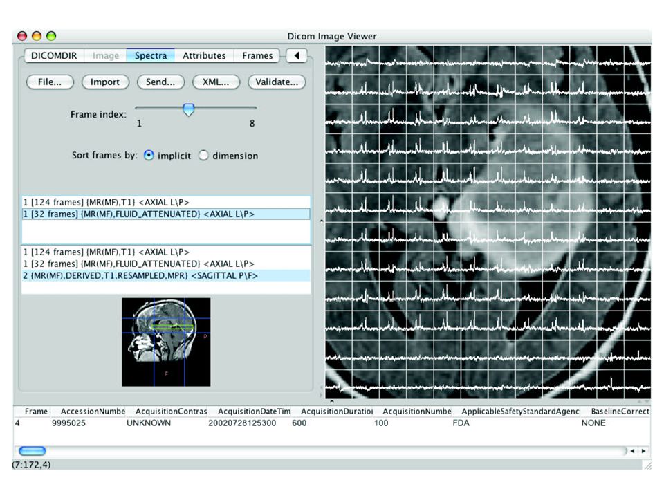
Single Voxel Spectroscopy 2000/144 Lactate NAA Creatine Choline

95
MRSI Example

96
MR Spectroscopy Storage of Spectroscopy Data Metabolite Maps

97
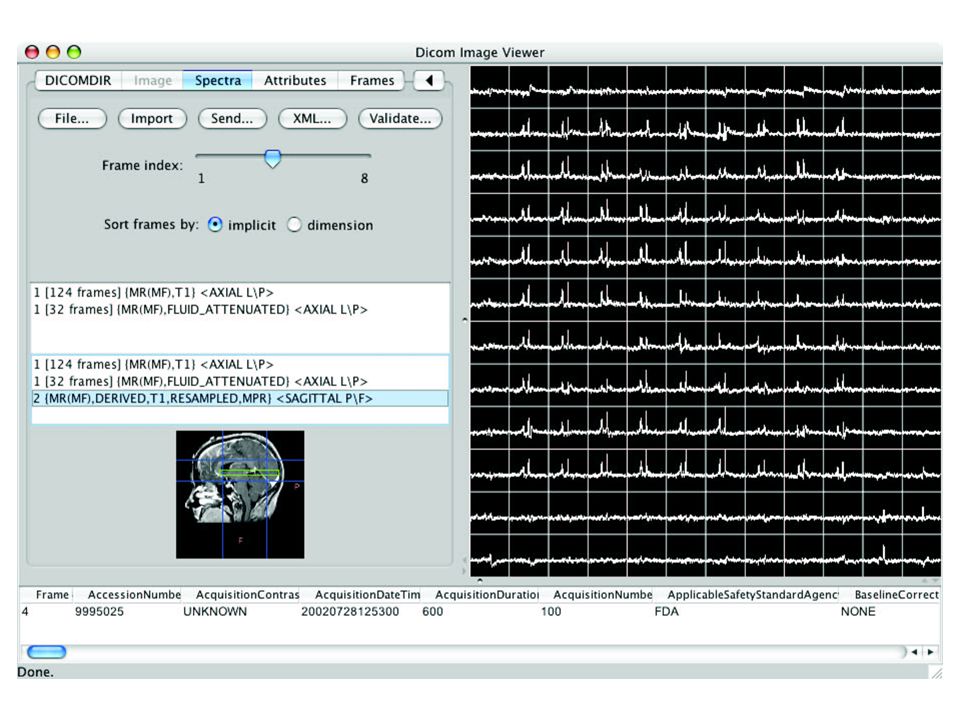
MR Spectroscopy Two types of data Spatially localized spectra (signal intensity versus frequency or time) Images of one particular part of the spectrum (chemical shift image or metabolite map) Metabolite maps are stored as images Spectra cannot be not stored as pixel data In the past - stored as screen saves of curves Now - MR Spectroscopy SOP Class Arrays of floating point and/or complex values 1D or 2D data for single or multiple voxels and frames Allows for interaction, analysis and quantitation
 Images of one particular part of the spectrum (chemical shift image or metabolite map) Metabolite maps are stored as images Spectra cannot be not stored as pixel data In the past - stored as screen saves of curves Now - MR Spectroscopy SOP Class Arrays of floating point and/or complex values 1D or 2D data for single or multiple voxels and frames Allows for interaction, analysis and quantitation")
101
Raw Data MR and CT have “raw data” prior to reconstruction into spatial domain images (k-space data, raw views) Need for different reconstructions Slice thickness and reconstruction interval Different convolution kernel (bone, lung) Different field of view For CAD versus human viewing Raw data is bulky and proprietary Local long term archival on modality possible but unusual and inconvenient, therefore time window for retrospective reconstruction is limited
 Need for different reconstructions Slice thickness and reconstruction interval Different convolution kernel (bone, lung) Different field of view For CAD versus human viewing Raw data is bulky and proprietary Local long term archival on modality possible but unusual and inconvenient, therefore time window for retrospective reconstruction is limited")
102
Raw Data SOP Class Goal is storage of encapsulated raw data in the PACS or other central archive Without standardizing raw data format Defines usual patient, study, series, instance attributes No standard payload - raw data assumed to be in private attributes Allows for storage and retrieval without understanding No expectation that different vendors will be able to use the data SOP Instance UID of raw data can be referenced from images and spectra

103
Problem: My CT scanner is choking the network Over the past decade, CT scanners have increased their ability to produce images by several orders of magnitude. Our 64-slice scanner can acquire 400 images per second. It makes everything go slow. The requirement for our PACS is to have the first screen of images painted in < 2 seconds.

104
Performance Opportunities New multi-frame object does not change TCP connection establishment Association establishment Common header information is not repeated But reduction is negligible compared to pixel data size Reduced latency (delay) between storage requests Creates opportunity for inter-slice (3D) compression Extremely implementation-dependent
 between storage requests Creates opportunity for inter-slice (3D) compression Extremely implementation-dependent")
105
Dataset (attributes+pixels) C-Store response (acknowledgement) C-Store request AssociationAssociation
 C-Store response (acknowledgement) C-Store request AssociationAssociation")
106
Dataset (attributes+pixels) C-Store response (acknowledgement) C-Store request UIDs Store, parse, check AssociationAssociation DB
 C-Store response (acknowledgement) C-Store request UIDs Store, parse, check AssociationAssociation DB")
107
Dataset (attributes+pixels) C-Store response (acknowledgement) C-Store request UIDs Store, parse, check AssociationAssociation DB
 C-Store response (acknowledgement) C-Store request UIDs Store, parse, check AssociationAssociation DB")
108
Dataset (attributes+pixels) C-Store response (acknowledgement) C-Store request UIDs Store, parse, check AssociationAssociation DB
 C-Store response (acknowledgement) C-Store request UIDs Store, parse, check AssociationAssociation DB")
109
Dataset (attributes+pixels) C-Store response (acknowledgement) C-Store request UIDs Store, parse, check AssociationAssociation DB
 C-Store response (acknowledgement) C-Store request UIDs Store, parse, check AssociationAssociation DB")
111
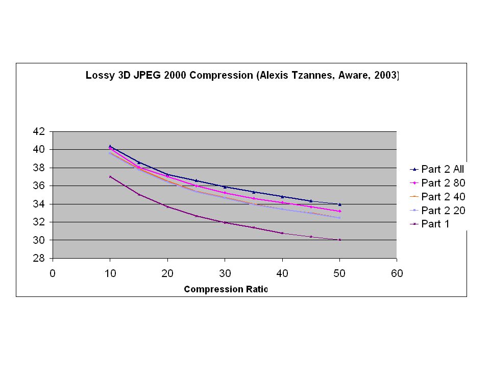
Multi-frame compression Original CT and MR SOP Classes are single frame Compression only possible within a single frame Lossless - typically 3:1 or 4:1 for CT and MR Multi-frame objects Opportunity to take advantage of redundancy between frames Spatial redundancy - JPEG 2000 Part 2 Lossless gain modest, lossy gain more substantial Motion prediction - MPEG-2 and others New schemes - H.264/MPEG-4 Part 10 Entire dataset (e.g., 3D volume) or adjacent slabs
 or adjacent slabs")
112
Single frame lossless compression

115
8:1 16:1 32:1 160:1 2D JPEG 2000 0.625mm slices

116
8:11:1

117
8:1

118
16:1

119
16:1 3D

120
8:11:1

121
32:1

122
160:1

123
Multi-frame compression performance reality check Lossless compression in 3D Slight gain - 15 to 20% smaller than 2D Lossy compression in 3D Modest gain - possibly 50% smaller than 2D But - only relatively modest loss before noticeable Perhaps (?) 16:1 Siddiqui et al, SCAR 2004 Thinner slices compress poorly due to noise 3D JPEG 2000 compression may be used to compensate Suggest using JND rather than PSNR as a metric Need more experiments Effect on observer performance unknown
 16:1 Siddiqui et al, SCAR 2004 Thinner slices compress poorly due to noise 3D JPEG 2000 compression may be used to compensate Suggest using JND rather than PSNR as a metric Need more experiments Effect on observer performance unknown")
124
But when ? Modality PACS

125
NEMA Initiatives MR test tools, images and spectra available CT test tools and images developed Implementation testing & demonstration June 2005 - SCAR demonstration - Here ! Now ! After SCAR, CT test tools and images released

126
NEMA & SCAR Test & Demonstration

127
Located in front of Exhibit Hall Open Friday 10am to 4pm Saturday 8am to 12pm

128
NEMA & SCAR Test & Demonstration Agfa Dynamic Imaging GE Hitachi INFINITT jMRUI McKesson Philips Siemens Toshiba Vital Imaging (not demonstrating)
")
129
Image Manager McKesson MR Philips WS INFINITT WS jMRUI CT Siemens WS GE CT Hitachi ModalityImage ManagerWorkstation

130
Image Manager Dynamic Imaging MR GE MR Siemens WS Agfa WS Philips WS Siemens MR Toshiba ModalityImage ManagerWorkstation

131
NEMA & SCAR - Purpose of the Test & Demonstration Participants Test that it works Identify problems and solutions Other vendors Show what work needs to be done Users Show that at works Begin to show some of the benefits Performance Interoperability of new attributes, dimensions, applications, spectroscopy

132
Not just MR & CT … Need for new multi-frame PET object Currently single slice Much renewed interest in PET-CT fusion First draft during SNM June 2005 meeting X-ray angiography letter ballot June 2005 Support for digital detectors New acquisition types Tomosynthesis

Similar presentations


 Integration Profile Kevin O’Donnell IHE Radiology Technical Committee Member, Toshiba.>")
 Integration Profile Kevin O’Donnell IHE Radiology Technical Committee Member, Toshiba.>")


 Kees Verduin Philips Healthcare Chair DICOM WG16.>")


 David Clunie – PixelMed.>")


 or multiple slices per file (new enhanced.>")
 Dynamic scanning implies 15 or more scans in rapid sequence within one.>")
