Download presentation
Presentation is loading. Please wait.

1
Treatment Technologies for Remediation of Hazardous Waste

2
Remediation of Hazardous Waste In-situ and Ex-situ Processes
History and Types of Hazardous Waste Sites Discussion about Past Practices Remediation Technologies Containment Grout curtains, slurry walls, capping Monitoring Source Control (Soils, Sediments, Sludges) Pump and treat, Air/steam stripping, soil vapor extraction Soil washing, solidification, mobile incineration Groundwater Treatment Carbon adsorption, bioremediation 2 2
 Pump and treat, Air/steam stripping, soil vapor extraction. Soil washing, solidification, mobile incineration. Groundwater Treatment. Carbon adsorption, bioremediation")
3
The Late 20th Century Became a Time to Focus on Man Made Pollution

4
Surface and Groundwater Contamination Leads to Health Problems, Water Shortage
Mining Acid mine drainage Heavy metals – Hg, Cr, Pb Industrial / Commercial Pollution Dyes and pigments Petroleum / gasoline Agricultural runoff Pesticides Nutrients – nitrates, phosphates Salinization – Sodium, chloride Sewage Pathogens - Enteric Nutrients – Nitrates, phosphates Contaminated animal feed Textile Waste Gasoline Mining Waste

5
The History of Hazardous Waste Pollution
In 1962, renowned author and naturalist, Rachel Carson, warned growing contamination “great underground seas” (i.e., groundwater) in “Silent Spring.” Love Canal – New York, USA. Buried barrels of chemicals underneath new housing development (1950s). Became main cause for the Superfund legislation. Removed from Superfund in Valley of the Drums – Kentucky, USA, 23 acre site with a large number of leaking drums. Fire at site in Not completely cleaned up until 1990. Times Beach – Missouri, USA community where contaminated oil was used for dust control from 5 5
 in Silent Spring. Love Canal – New York, USA. Buried barrels of chemicals underneath new housing development (1950s). Became main cause for the Superfund legislation. Removed from Superfund in Valley of the Drums – Kentucky, USA, 23 acre site with a large number of leaking drums. Fire at site in Not completely cleaned up until Times Beach – Missouri, USA community where contaminated oil was used for dust control from")
6
Superfund Sites in the US
Current Proposed Complete Source: Wikipedia Superfund 6

7
Various Pathways Exist for Contamination From Land Disposal
7 7

8
Solid Waste can Directly Impact Human Health
Solvents – Gasoline, diesel, chlorinated Leachates – Acid waste, heavy metals Hazardous waste – Metals, paints, solvents, pesticides Leaking fuel tanks – Gasoline, diesel Refuse - Decaying animal and plant matter

9
Contaminated Land Disposal is Closely Linked to Water Cycle
9 9

10
Drinking Water, Wastewater Contaminants Directly Affect Public Health
Pathogens Bacteria – Enteric, fecal Protists – Cysts and spores Virus - Enteric Metals Copper Lead Arsenic Disinfection byproducts Trihalomethane - CHCl3,,CH2Cl2, CH2ClBr Haloacetic acid – CH2ClCO2H Pesticides

11
General Lessons Learned in Remediating Hazardous Waste Sites
The larger the scope of contamination, the more limited the cleanup options. After the pollutant has dispersed the groundwater may be undrinkable for years Liability and funding for remediation may be quite expensive When land disposed, individual wastes frequently mix with other wastes. When these mixtures are released to the environment, their cleanup is further complicated by combining with environmental media (i.e., soils, clay, groundwater). Once HW and/or mixtures are released to the environment, particularly groundwater, the ability to fully cleanup and restore the resource is severely limited, if not rendered impossible. The compromises and complexities that are triggered by the environmental release of hazardous waste from land disposal are seemingly endless and daunting. The 2 Graphics below depict the many pathways of environmental contamination from leaking land disposal units, and raise a series of issues. How far has the contamination spread? What contaminants are involved? Who is responsible for what? To what level should cleanup occur? What is the future land use? How much can we afford to spend on cleanup? Can we afford to not restore the resource? Is cleanup even feasible given the dimensions of the contamination? What if cleanup isn’t feasible? 11 11
. Once HW and/or mixtures are released to the environment, particularly groundwater, the ability to fully cleanup and restore the resource is severely limited, if not rendered impossible. The compromises and complexities that are triggered by the environmental release of hazardous waste from land disposal are seemingly endless and daunting. The 2 Graphics below depict the many pathways of environmental contamination from leaking land disposal units, and raise a series of issues. How far has the contamination spread What contaminants are involved Who is responsible for what To what level should cleanup occur What is the future land use How much can we afford to spend on cleanup Can we afford to not restore the resource Is cleanup even feasible given the dimensions of the contamination What if cleanup isn’t feasible")
12
More Lessons Learned Cleanup is much more costly and time consuming than properly managing wastes in the first place. Treatment and excavation costs Continuous expense for monitoring Landfills, lagoons, piles and land spreading will often create large areas of contamination Chlorinated solvents are often high density and thus will “sink” toward groundwater. (DNAPL) Once hazardous waste are released to the environment, cleanup of those releases far exceeds the challenges of properly managing these same waste if they were newly generated in terms of cost, time, difficulty, and health impacts. A newly generated waste that could have been completely destroyed if properly managed in the first instance, if land disposed as an untreated waste can completely destroy a drinking water aquifer or other resource. Placement of untreated hazardous waste (HW) into land disposal units (i.e., landfills, lagoons, pile, land treatment) will virtually ensure environmental contamination. Land disposal of chlorinated organic wastes, particularly liquid solvents, will result in environmental and/or groundwater contamination. 12 12
 Once hazardous waste are released to the environment, cleanup of those releases far exceeds the challenges of properly managing these same waste if they were newly generated in terms of cost, time, difficulty, and health impacts. A newly generated waste that could have been completely destroyed if properly managed in the first instance, if land disposed as an untreated waste can completely destroy a drinking water aquifer or other resource. Placement of untreated hazardous waste (HW) into land disposal units (i.e., landfills, lagoons, pile, land treatment) will virtually ensure environmental contamination. Land disposal of chlorinated organic wastes, particularly liquid solvents, will result in environmental and/or groundwater contamination")
13
Remediation can Take Various Pathways
Containment: Seals off all possible exposure pathways between a hazardous waste disposal site and environment. Slurry Walls Grout curtains Drainage systems Capping Monitoring 13 13

14
Basic Grout Curtain Containment System
Slurry Walls and Grout Curtains are Containment Technologies Slurry Wall Basic Grout Curtain Containment System 14 14

15
Containment Remediation- Slurry Wall Emplaces Impermeable Barrier
Dig trench around an area Backfill trench with an impermeable material (clay) slurry typically a clay-type material such as bentonite. The most common type of slurry wall construction is the trench method in which a trench is excavated in the presence of a bentonite-water slurry to a desired depth. Slurry walls can either be constructed as a straight trench, or in a circular pattern to encompass the disposal unit as depicted in the graphics below. The advantages of slurry walls are that they are perhaps the most simple structures to construct and they have low maintenance requirements. Slurry walls are limited in areas of rocky ground where additional excavation is necessary. Additionally, bentonites deteriorate when exposed to high ion strength leachates. Cross Section of a Slurry Wall 15 15
 slurry. typically a clay-type material such as bentonite. The most common type of slurry wall construction is the trench method in which a trench is excavated in the presence of a bentonite-water slurry to a desired depth. Slurry walls can either be constructed as a straight trench, or in a circular pattern to encompass the disposal unit as depicted in the graphics below. The advantages of slurry walls are that they are perhaps the most simple structures to construct and they have low maintenance requirements. Slurry walls are limited in areas of rocky ground where additional excavation is necessary. Additionally, bentonites deteriorate when exposed to high ion strength leachates. Cross Section of a Slurry Wall")
16
Slurry Walls are Impermeable Barriers Made of Clay Materials
Slurry Walls can be placed in a circular fashion to divert groundwater around contaminant Plan View Slurry Wall 16 16

17
Grout Curtains Injected in the Subsurface Solidification Reduces Permeability
Grouting Inject liquid, slurry, or emulsion under pressure into the soil Slury fills pore space Two types Particulate – solid + liquid solidifies Chemical – Liquid +liquid that gels Grouts are limited when high water table or rapid GW flow The fluid injected will move away from the point of injection to occupy the available pore spaces. As time passes, the injected fluid will solidify, thus resulting in a decrease in the original soil permeability and an increase in the soil-bearing capacity. Grouts are usually classified as particulate or chemical. Particulate grouts consist of water plus particulate matter which will solidify. Chemical grouts usually consist of two or more liquids which will gel when they come in contact with each other. Grouts, both particulate and chemical have been used for over 100 years in construction and soil stabilization projects. Grouting is limited to granular types of soil that have pore size large enough to accept grout fluids under pressure yet small enough to prevent significant pollutant migration. Grouting is also limited in situations of high water tables and rapidly flowing groundwater. The Graphic below compares slurry wall to grout curtain construction. 17 17

18
Containment Remediation Proceeds in Steps, Combined with Extraction
The Figure on the bottom right depicts the typical initial phase of remedial response whereby a barrier, either slurry wall or grout curtain, is constructed downgradient of the groundwater flow with extraction wells installed inside the perimeter of the barrier to extract contaminated groundwater for further treatment. An upgradient system is also depicted. Downgradient Barrier and Extraction Wells (Top and Side Views) Upgradient Barrier and Extraction Wells 18 18
 Upgradient Barrier and Extraction Wells")
19
Love Canal Capping Containment and Drain
“Love Canal” is the name given to the one of the most notorious leaking land disposal sites in the U.S. Located near Buffalo, New York, Love Canal was a former waterway canal that was used as a disposal pit for thousands of drums and tons of waste sludges by a major chemical company for over twenty years. In 1978, leakage from the Love Canal disposal pit began to infiltrate the basements and water supplies of nearby homes, resulting in resident relocation and closure of over 400 homes. The discovery of Love Canal triggered a legislative response in the form of the 1980 “Superfund” Law to ensure resources and authority to cleanup such sites. The remedy at Love Canal largely involves a containment system accompanied by an engineering cap to prevent rainwater infiltration and a drainage collection system for leaking wastes, which are subsequently treated. The site was simply too immense and the dangers of excavation too great to allow direct management of all buried wastes. This type of remedy is typical for a vary large industrial landfill. Love Canal Barrier, Drain and Capping System 19 19

20
Groundwater Monitoring is Necessary to Protect Drinking Water
All containment remedies are accompanied by an extensive groundwater monitoring. 20 20

21
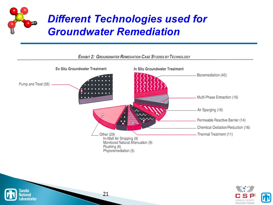
Different Technologies used for Groundwater Remediation
21 21 21
22
Groundwater Remediation Reduces Spread of Contamination
Principally used to remove or reduce hazardous waste contamination from the groundwater aquifer passing through or near the site. Pump and Treat (including lowering of GW table) Steam Stripping Air Stripping Carbon Adsorption Bioremediation The most basic groundwater treatment system is known as “pump and treat.” This method involves subsurface drains to collect contaminated groundwater, lowering of the groundwater table to below the level of the contaminants and collect ion of the contaminated groundwater for subsequent treatment or discharge as depicted in the Graphic below. The treatment system employed for the contaminated groundwater that is collected by the “pump and treat” an be simple and basic or highly complex. It may involve a simply unitary process such as biotreatment, or may involve multiple technologies, also known as a “treatment train” to address the diversity of contaminants in the groundwater. Such treatment trains are not limited to the technology discussed in this section (i.e., carbon adsorption, air stripping, steam stripping, and bioremediation), but rather may involve any one or more of the technologies discussed in Section VI – Source Control Technologies, below 22 22
 Steam Stripping. Air Stripping. Carbon Adsorption. Bioremediation. The most basic groundwater treatment system is known as pump and treat. This method involves subsurface drains to collect contaminated groundwater, lowering of the groundwater table to below the level of the contaminants and collect ion of the contaminated groundwater for subsequent treatment or discharge as depicted in the Graphic below. The treatment system employed for the contaminated groundwater that is collected by the pump and treat an be simple and basic or highly complex. It may involve a simply unitary process such as biotreatment, or may involve multiple technologies, also known as a treatment train to address the diversity of contaminants in the groundwater. Such treatment trains are not limited to the technology discussed in this section (i.e., carbon adsorption, air stripping, steam stripping, and bioremediation), but rather may involve any one or more of the technologies discussed in Section VI – Source Control Technologies, below")
23
Source Control Prevents Continued Release or Spread of Contaminants
Used to remove or reduce hazardous waste contamination from sludges and soils near the site. Soil Vapor Extraction (SVE) Air Sparging Bioremediation (including Bioventing and Bioreactors) Air Stripping and Steam Stripping Soil Washing and Soil Flushing Stabilization/Solidification Vitrification Thermal Desorption Mobile Incineration Source Control Actions Remedies involving the construction or installation of those actions and technologies necessary to prevent the continued release of hazardous waste (primarily from a soil or sludge source on top of or within the ground, or in a building) into the environment. Exhibit 1 above summarizes the technology usage patterns for soil remediation in the U.S. Examples include: 23 23
 Air Sparging. Bioremediation (including Bioventing and Bioreactors) Air Stripping and Steam Stripping. Soil Washing and Soil Flushing. Stabilization/Solidification. Vitrification. Thermal Desorption. Mobile Incineration. Source Control Actions Remedies involving the construction or installation of those actions and technologies necessary to prevent the continued release of hazardous waste (primarily from a soil or sludge source on top of or within the ground, or in a building) into the environment. Exhibit 1 above summarizes the technology usage patterns for soil remediation in the U.S. Examples include:")
24
Pump and Treat Basic Pump and Treat System (Top and Side Views) 24 24
 24 24")
25
Air and Steam Stripping for Source Control
Primary use of stripping technologies is in groundwater treatment. However, both are often used as part of a source control “treatment train.” For example: soil contaminated with chlorinated solvents has SVE as primary technology. SVE vapors are sent to a steam stripper for separation of solvents from water vapor. Concentrated solvent stream from stripper is sent to thermal oxidizer for final treatment. Steam Stripper Air Stripper These can be used in conjunction with Soil Vapor Extraction or Groundwater Treatment 25 25

26
Air Stripping Process - Water Treatment
Stripping (i.e., air or steam) is a unit operation in which dissolved molecules are transferred from a liquid to a flowing gas or vapor stream. Driving force is the concentration gradient between the liquid and gas phase. Air Stripping is a mass-transfer process whereby volatile contaminants are stripped out of the aqueous solution and into the air. The process exposes the contaminated water to a fresh air supply which results in a net mass transfer of contaminants from liquid phase to the gas phase. Moving gas is air at ambient temperature and pressure. Used to remove volatile dissolved organic compounds from aqueous waste. Contaminants are not destroyed by the air stripping, but rather are transferred into the air stream where they may need further treatment such as biological treatment , thermal destruction, or some form of oxidation. Air stripping applies to volatile and semi-volatile organic compounds. It does not apply to low volatility compounds, metals, or inorganic contaminants. Feed concentration must be less than 100mg/L. The following diagrams reflect the typical configuration for an air stripping pack tower and integrated treatment process using an air stripper as one of its key components. Air stripping is one of the most common technologies used to treat volatile contaminants in contaminated groundwater. Air Stripping System Packed Tower 26 26
 is a unit operation in which dissolved molecules are transferred from a liquid to a flowing gas or vapor stream. Driving force is the concentration gradient between the liquid and gas phase. Air Stripping is a mass-transfer process whereby volatile contaminants are stripped out of the aqueous solution and into the air. The process exposes the contaminated water to a fresh air supply which results in a net mass transfer of contaminants from liquid phase to the gas phase. Moving gas is air at ambient temperature and pressure. Used to remove volatile dissolved organic compounds from aqueous waste. Contaminants are not destroyed by the air stripping, but rather are transferred into the air stream where they may need further treatment such as biological treatment , thermal destruction, or some form of oxidation. Air stripping applies to volatile and semi-volatile organic compounds. It does not apply to low volatility compounds, metals, or inorganic contaminants. Feed concentration must be less than 100mg/L. The following diagrams reflect the typical configuration for an air stripping pack tower and integrated treatment process using an air stripper as one of its key components. Air stripping is one of the most common technologies used to treat volatile contaminants in contaminated groundwater. Air Stripping System. Packed Tower")
27
Steam Stripping Process – Water Treatment
Steam stripping uses steam to evaporate volatile organics from aqueous wastes. Steam stripping is essentially a continuous fractional distillation process carried out on a packed or tray tower. Live steam is used as the gas phase. Clean steam provides direct heat to the bottom of the column and gas flows from the bottom to the top of the tower. The resulting residuals are: 1) contaminated steam condensate, 2) recovered solvent, and 3) stripped effluent. The organic vapors are sent through a condenser in preparation for further purification treatment. Possible post-treatment includes incineration, carbon adsorption, or land disposal. More efficient than air stripping; applicable to less volatile compounds. Volatile organic concentrations up to 5% can be removed. Can be used to separate volatiles from other non-aqueous phases, such as oil and grease, paint solids, polymers and resins. Process resembles distillation as depicted in the Graphic below. Steam stripping is used to treat aqueous wastes contaminated with chlorinated hydrocarbons, aromatics, alcohols, and high-boiling-point chlorinated aromatics, such as pentachlorophenol. Steam stripping will treat less volatile and more soluble wastes than will air stripping and can handle a wide concentration range. Steam stripping requires an air pollution control mechanism to eliminate toxic emissions. Typical Steam Stripping Flow Diagram 27 27
 contaminated steam condensate, 2) recovered solvent, and 3) stripped effluent. The organic vapors are sent through a condenser in preparation for further purification treatment. Possible post-treatment includes incineration, carbon adsorption, or land disposal. More efficient than air stripping; applicable to less volatile compounds. Volatile organic concentrations up to 5% can be removed. Can be used to separate volatiles from other non-aqueous phases, such as oil and grease, paint solids, polymers and resins. Process resembles distillation as depicted in the Graphic below. Steam stripping is used to treat aqueous wastes contaminated with chlorinated hydrocarbons, aromatics, alcohols, and high-boiling-point chlorinated aromatics, such as pentachlorophenol. Steam stripping will treat less volatile and more soluble wastes than will air stripping and can handle a wide concentration range. Steam stripping requires an air pollution control mechanism to eliminate toxic emissions. Typical Steam Stripping Flow Diagram")
28
Carbon Adsorption - Water Treatment and Soil Vapor
Adsorption means that molecules of a dissolved contaminant become attached to the surface of a solid adsorbent. The most widely used adsorbent is granular activated carbon (GAC), because its porous structure provides a relatively large surface area per unit volume. Adsorption involves both chemical and physical forces. Chemical adsorption is due to actual chemical bonding at the solids surface. Environmental engineers commonly use carbon adsorption to remove organic contaminants from water or air such as chlorinated hydrocarbons, PCB’s, chlorophenols, and chlorobenzenes. The collected contaminants on the carbon bed are periodically removed for further treatment such as thermal destruction, which typically occurs at the same time that the activated carbon is regenerated, or for disposal. The 2 Figures below depict a fixed bed Carbon Adsorption Unit, and a typical Carbon Adsorption System. GAC is frequently used for groundwater contamination with low levels of chlorinated hydrocarbons. Highly contaminated groundwater can exhaust the carbon beds at a rate which makes this remedy impractical. Carbon Adsorption System Fixed-bed Carbon Adsorption Unit 28 28
, because its porous structure provides a relatively large surface area per unit volume. Adsorption involves both chemical and physical forces. Chemical adsorption is due to actual chemical bonding at the solids surface. Environmental engineers commonly use carbon adsorption to remove organic contaminants from water or air such as chlorinated hydrocarbons, PCB’s, chlorophenols, and chlorobenzenes. The collected contaminants on the carbon bed are periodically removed for further treatment such as thermal destruction, which typically occurs at the same time that the activated carbon is regenerated, or for disposal. The 2 Figures below depict a fixed bed Carbon Adsorption Unit, and a typical Carbon Adsorption System. GAC is frequently used for groundwater contamination with low levels of chlorinated hydrocarbons. Highly contaminated groundwater can exhaust the carbon beds at a rate which makes this remedy impractical. Carbon Adsorption System. Fixed-bed Carbon Adsorption Unit")
29
Different Technologies used for Soil Remediation
29

30
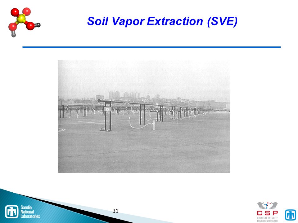
Soil Vapor Extraction (SVE)
Volatiles swept from groundwater Optional air sparge Volatiles captured or treated at surface This technology removes volatile compounds from contaminated groundwater by inducing airflow through the aquifer via a vacuum and pressure gradient that induces volatiles to diffuse through the extraction wells. The volatiles are collected as gases and treated above ground. The technology is effective for halogenated volatiles and fuel hydrocarbons. The technology is also cost -effective when large volumes are soil are involved, since treatment takes place on-site, the risks and costs associated with transporting large volumes of contaminated soils are eliminated. SVE is less effective in soils with low air permeability, low temperatures, or high carbon content. In addition, the collected volatiles typically require additional ultimate treatment via thermal oxidation, catalytic oxidation biological treatment or other method. The 3 Graphics below depict typical SVE flow diagrams (top) and a field installation of an SVE system (bottom). 30 30
 and a field installation of an SVE system (bottom)")
31
Soil Vapor Extraction (SVE)
31 31
32
Air Sparging Enhanced SVE
SVE commonly enhanced with air sparging. Air sparging involves the active pumping of ambient air into the subsurface soil and groundwater to enhance the collection of volatiles through the SVE system. 32 32

33
Bioremediation can Occur In-situ or Ex-situ
In-situ typically enhances naturally occurring biological activity circulating nutrient and oxygen-enriched water-base solution forced air movement provides oxygen to enhance naturally occurring microbes. Bioventing has air flow rate lower than Soil Vapor Extraction (SVE) deliver oxygen minimizing volatilization. In-situ biological treatment is effective for non-halogenated volatiles and fuel hydrocarbons. Technology is less effective for non-biodegradable compounds and for soils with low permeability. 33 33
 deliver oxygen. minimizing volatilization. In-situ biological treatment is effective for non-halogenated volatiles and fuel hydrocarbons. Technology is less effective for non-biodegradable compounds and for soils with low permeability")
34
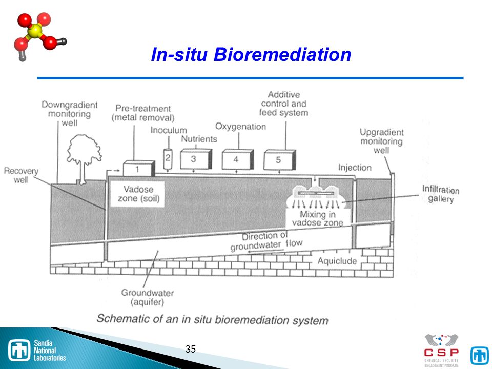
Biotreatment of Groundwater (In-situ)
Use natural occurring and/or enhanced organisms Enhanced biotreatment involves add O2 and nutrients. Proper mixture of O2, nutrients and bacteria are site-specific and chemical-specific. Technique limited by pH, temp, toxicity of contaminants, and to aquifers with high permeability. Advantages:cost, minimal surface facilities minimal public exposure. 34 34

35
In-situ Bioremediation
35 35
36
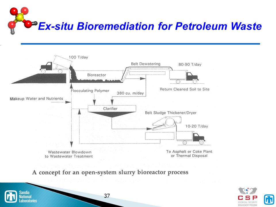
Bioremediation for Petroleum Waste (Ex-situ)
Ex Situ bioremediation involves excavating the contaminated soil Placing it into biotreatment cells Adding nutrients to enhance biological activity Periodically turning it over to aerate the water. The moisture, heat, nutrients, oxygen, and pH are usually controlled in the process. Separation of decontaminated solids In addition, volatile emissions as well as leachate from the biotreatment cells need to be controlled. The technology is most effective for soils contaminated with fuel hydrocarbons, which can be completely destroyed and the soil reused. The Figure below depicts a treatment system for removal of total petroleum hydrocarbon (TPH) from soils. Soil, nutrient buffer, and water are mixed in a reactor at atmospheric pressure for an undetermined time, but typically less than two weeks 36 36
 from soils. Soil, nutrient buffer, and water are mixed in a reactor at atmospheric pressure for an undetermined time, but typically less than two weeks")
37
Ex-situ Bioremediation for Petroleum Waste
37 37
38
Bioremediation Organisms
A variety of bacteria and yeast have been successfully deployed in situ and ex situ biological treatment systems. 38 38

39
Soil Washing: Ex-situ Excavation
Soil washing is an ex situ technique that removes adsorbed contaminants from soil particles. The process involves excavating the contaminated soil and washing it with a leaching agent, a surfactant, or chelating agent, or adjusting the pH. Sometimes extraction agents are added to enhance the process. The process reduces the volume of contaminants. However, residual suspended solids and sludges from this process may need further treatment since they contain higher concentrations of contaminants than the original. This technology is effective for halogenated semi-volatiles, fuel hydrocarbons, and inorganics. The technology is less effective when the soil contains a high percentage of silt and clay particles or high organic content. While the technology reduces the volumes of contaminants, the toxicity of these contaminants is unchanged. Excavation Wash soil with leaching agent or surfactant Not effective with clay or high organic content 39 39

40
Soil Flushing : In-situ
Soil flushing is an in situ process whereby environmental engineers apply a water-based solution to the soil to enhance the solubility of the contaminant. The water-based solution is applied through injection wells or shallow infiltration galleries. The contaminants are mobilized by solubilization or through chemical reactions with the added fluid. The generated leachate must be intercepted by extraction wells, or subsurface drains and pumped to the surface for above ground treatment., as depicted in the Figure below. The technology is available for non-halogenated volatile organics and with soils with high permeability. The technology however, is less effective for soils with low permeability or with particles that strongly adsorb contaminants such as clay. Apply water solution to enhance contaminant mobility Generated leachate intercepted Especially good for halogenated and high permeability soil 40 40

41
Solidification – Stabilization (S/S)
Solidification methods physically encapsulate hazardous waste into a solid material matrix of high structural integrity. Stabilization techniques chemically treat hazardous waste by converting them into a less soluble, mobile or toxic form. Principally used for metal-bearing wastes. Limited applicability to organic wastes. Typically used to concentrate contaminants prior to S/S. 2 Main types of processes: cement and pozzolanic. 41 41

42
Cement Stabilization (Ex-situ)
Description Slurry of wastes and water is mixed with portland cement to form a solid. Advantages Low cost Readily available mixing equipment Relatively simple process Suitable for use with metals Disadvantages Solids are suspended, not chemically bound subject to leaching Doubles waste volume Requires secondary containment Incompatible with many wastes Organics, some sodium salts, silts, clays, and coal or lignite. 42 42

43
Pozzolanic Processes (Ex-situ)
Description Waste is chemically reacted with lime and a fine-grained siliceous material (fly ash, ground blast furnace slag, cement kiln dust) to form a solid. Advantages Low costs; Readily available mixing equipment; Suitable for power-plant wastes (FGD sludges, etc.) as well as a wide range of industrial wastes, including metals, waste oil, and solvents Disadvantages Increases waste volume May be subject to leaching Requires secondary containment. 43 43
 to form a solid. Advantages. Low costs; Readily available mixing equipment; Suitable for power-plant wastes (FGD sludges, etc.) as well as a wide range of industrial wastes, including metals, waste oil, and solvents. Disadvantages. Increases waste volume. May be subject to leaching. Requires secondary containment")
44
Solidification - Stabilization
Generic Elements Of A Typical Ex-situ S/S Process Solidification - Stabilization 44 44

45
Metals/Cyanide S/S Treatment Train
S/S most commonly used for heavy metals and or cyanides. 45 45

46
In-situ Vitrification Process - Specialized S/S
Thermal process converts contaminated soil to chemically inert stable glass/crystalline product. Electrical current produces heat –melts soil Molten zone grows destroying/encapsulating hazardous constituents and metals Hood for volatile emissions Square configuration of 4 molybenum and graphite electrodes inserted into area to desired depth. Conductive mixture of flaked graphite and glass frit is placed among the electrodes as a starter path. Heat is formed at temperatures up to 2000 C above soil melting temp of 1400 C. Hood must be placed over the area to collect any VOCs or other emissions to an off-gas treatment system. Principally is metals treatment technology. 46 46

47
Mobile Incineration Involves a wide variety of units such as small liquid waste incinerators at right. Multiple trailer rotary kiln for complex sludges and drummed waste, below. Infrared (electrically heated) “soil roaster” are also used. Infrared is a form of indirect heating using electric current instead of fuel oil to generate heat. Infrared Incineration 47 47
 soil roaster are also used. Infrared is a form of indirect heating using electric current instead of fuel oil to generate heat. Infrared Incineration")
48
Acknowledgement and Background
Richard Fortuna, President, Strategic Environmental Analysis, L.C. 31 years experience evaluating technologies and developing preventive policies for HW management Developed key provisions of the U.S. statute governing daily waste management; The Resource Conservation and Recovery Act (RCRA) Participated in enactment of the “Superfund” cleanup law. RCRA is intended to prevent the creation of additional “Superfund” or leaking waste sites Worked with over 200 companies in evaluating waste treatment technologies and policies Authored a text on major reforms to RCRA. 48 48
 Participated in enactment of the Superfund cleanup law. RCRA is intended to prevent the creation of additional Superfund or leaking waste sites. Worked with over 200 companies in evaluating waste treatment technologies and policies. Authored a text on major reforms to RCRA")
Similar presentations


 Roxane Fisher and Mark Ferguson.>")


 that reduce the quantity of waste requiring solidification/stabilization,>")


