Download presentation
Presentation is loading. Please wait.

1
Session 2013 Lecture # 2 Instructor Kashif Shahzad

2
Course Details Text Book: Electronic Communication System by Kennedy and Davis Reference Text: Modern Digital and Analog Communication System by B.P. Lathi (Soft copy is available on group page) Course Instructor: Kashif Shahzad Email: kashifshahzad31@yahoo.comkashifshahzad31@yahoo.com Cell: +92 333 5186231 Course homepage: http://groups.yahoo.com/group/prestonadvcommsystems http://groups.yahoo.com/group/prestonadvcommsystems
 Course Instructor: Kashif Shahzad Cell: Course homepage: ")
4
Course Breakdown Assignments:10% Quizzes:10% Others:05% Mid Term:25% Terminal:50%

5
Learning Objective Explain the principles of a communication systems Discuss the nature of information, different types of signals involved and their characteristics Make the distinction between Analog and Digital communication systems Determine the need of modulation and differentiate various type of modulation techniques in time, frequency domain Important steps in analog to digital conversion, PCM, PAM, PPM etc “We will deal with almost every important phenomenon at physical layer level”

6
Review of last week (Lecture 1) Basic concept of Data, Information and Redundancy Relationship of Data and Signals Signals and Systems Different types of Signals (Chp 2 Reference) Analog vs Digital Continuous vs Discrete Periodic vs Aperiodic Energy vs Power Stochastic vs Deterministic
 Basic concept of Data, Information and Redundancy Relationship of Data and Signals Signals and Systems Different types of Signals (Chp 2 Reference) Analog vs Digital Continuous vs Discrete Periodic vs Aperiodic Energy vs Power Stochastic vs Deterministic")
7
Today’s Menu Essential Parts of Communication System Transmitter Receiver Channel Time and frequency domain relationship Concept of Spectrum & Bandwidth Concept of Passband & Baseband Signals Modulation & Demodulation Fourier Series (3 types)
")
8
COMMUNICATION OVER LONG DISTANCES IS NO LONGER A PROBLEM. 8 Communication : To transfer information from one place to another

9
Communication System History 1837 – Samuel Morse invented telegraph. 1858 – First telegraph cable across Atlantic (Canada – Ireland) 1876 – Alexander Graham Bell invented telephone. 1988 – Heinrich Hertz introduce electromagnetic field theory. 1897 – Marconi invented wireless telegraph. 1906 – Radio communication system was invented. 1923 – Television was invented. 1938 – Radar and microwave system was invented for World War II. 1950 – TDM was invented. 1956 – First telephone cable was installed across Atlantic. 1960 – Laser was invented 1962 – Satellite communication 1969 – Internet DARPA 1970 – Corning Glass invented optical fiber. 1975 – Digital telephone was introduced. 1985 – Facsimile machine. 1988 – Installation of fiber optic cable across Pacific and Atlantic. 1990 – World Wide Web and Digital Communication. 1998 – Digital Television. 9
 1876 – Alexander Graham Bell invented telephone – Heinrich Hertz introduce electromagnetic field theory – Marconi invented wireless telegraph – Radio communication system was invented – Television was invented – Radar and microwave system was invented for World War II – TDM was invented – First telephone cable was installed across Atlantic – Laser was invented 1962 – Satellite communication 1969 – Internet DARPA 1970 – Corning Glass invented optical fiber – Digital telephone was introduced – Facsimile machine – Installation of fiber optic cable across Pacific and Atlantic – World Wide Web and Digital Communication – Digital Television. 9.")
10
10 The Real Aim “If the information that you want to send is your voice, how to make sure that what you are saying is understood by your friend?” Basic Parts of a Communication System

11
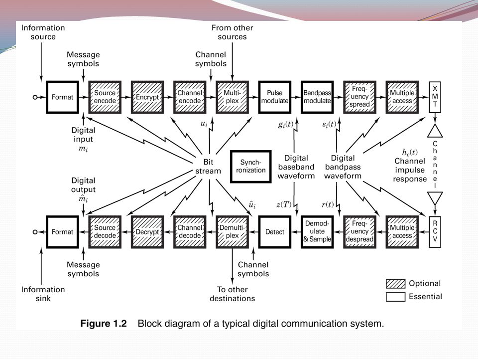
Basic Communication System 11 Transmitter Transmission Medium Receiver Input Transducer Output Transducer Noise wired / wireless m tx (t) s(t)s(t)r(t)r(t) p tx (t) n(t)n(t) m rx (t)p rx (t) s(t) – Input signal; audio, video, image, data etc. m tx (t) – Modulating signal; input signal that has been converted to electrical signal. p tx (t) – Modulated signal transmit by the transmitter. n(t) – Noise signal. p rx (t) – Modulated signal receive by the receiver. m rx (t) – Modulating signal at the receiver. r(t) – Output signal.
 – Modulating signal; input signal that has been converted to electrical signal. p tx (t) – Modulated signal transmit by the transmitter. n(t) – Noise signal. p rx (t) – Modulated signal receive by the receiver. m rx (t) – Modulating signal at the receiver. r(t) – Output signal..")
12
Component Function in Basic Communication System 12 Input Transducer – convert input signal, s(t) in electrical forms. eg: microphone. Transmitter – involve modulation process – convert modulating signal, m tx (t) to modulated signal, p tx (t). And finally transmit the signal. Transmission medium – connecting the transmitter and the receiver that enable the modulated signal, p tx (t) propagate through the medium. Receiver – receive the modulated signal, p rx (t) and then convert the signal to modulating signal, m rx (t) through the process called demodulation. Output Transducer – convert the modulating signal, m rx (t) to its original forms (output signal), r(t) that is useful to the users. eg: loud speaker.
 to modulated signal, p tx (t). And finally transmit the signal. Transmission medium – connecting the transmitter and the receiver that enable the modulated signal, p tx (t) propagate through the medium. Receiver – receive the modulated signal, p rx (t) and then convert the signal to modulating signal, m rx (t) through the process called demodulation. Output Transducer – convert the modulating signal, m rx (t) to its original forms (output signal), r(t) that is useful to the users. eg: loud speaker..")
13
Communication Systems

14
Transmission Medium (Guided) Twisted pair Unshielded Twisted Pair (UTP) Shielded Twisted Pair (STP) Coaxial Fiber Optic Waveguide 14
 Twisted pair Unshielded Twisted Pair (UTP) Shielded Twisted Pair (STP) Coaxial Fiber Optic Waveguide 14")
15
Physical Transmission Media 100 Mbps is how many bits per sec? Which is bigger: 10,000 Mbps, 0.01Tbps or 10Gbps? Wireless channel capacity:

16
Concept of Time Domain and Frequency Domain All signals exist in real world in time domain Oscilloscopes shows signals as a function of time But it is yet again the representation of data as a function of time We can view the same information as a function of some other variable which may have a useful meaning In analysis composite signals are hard to analyze Hence we use frequency domain

17
WHAT IS FREQUENCY SPECTRUM IT CONSISTS OF ALL FREQUENCIES CONTAINED IN THE WAVEFORM AND THEIR RESPECTIVE AMPLITUDE IN THE FREQUENCY DOMAIN. 17

18
Time vs Frequency domain

19
Another Look Time Domain Sine wave viewed as an impulse function in frequency domain

20
Spectrum Analyzer

21
Oscilloscope vs Spectrum Analyzer

22
Frequency Spectrum 22

23
Concept of Bandwidth IT IS THE DIFFERENCE BETWEEN THE HIGHEST FREQUENCIES AND THE LOWEST FREQUENCIES OF THE INPUT SIGNAL FREQUENCIES (f B = 2f m ). The bandwidth of a communication signal bandwidth of the information signal. 23

24
Data (nonelectrical) Electrical Waveform Without any shift in the range of frequencies of the signal The signal is in its original form, not changed by modulation. Baseband is the original information that is to be Sent. It starts from zero and to some specific frequency WHAT IS BASEBAND SIGNAL ?

25
WHAT IS PASSBAND SIGNAL ? After modulation, the original baseband signal is moved to a range of frequency which far more higher than the baseband signal So it’s a range of frequency shifted after modulation

26
What is Modulation MODULATION IS THE PROCESS OF CHANGING SOME PROPERTYOF THE INFORMATION SOURCES INTO SUITABLE FORM FOR TRANSMISSION THROUGH THE PHISICAL MEDIUM/CHANNEL “Process of coverting baseband signal into passband signal is called modulation” It is performed in the Transmitter by a device called Modulator. 26

27
Typical Modulation

28
Modulation 28

29
TYPE OF MODULATION Amplitude Modulation (AM) Frequency Modulation (FM) Phase Modulation (PM) 29
 Frequency Modulation (FM) Phase Modulation (PM) 29")
30
TYPE OF MODULATION 30

31
Need for Modulation Channel assignment (various information sources are not always suitable for direct transmission over a given channel) Efficient Utilization of bandwidth and multiplexing Reduce noise &interference Reduction in antenna size 31
 Efficient Utilization of bandwidth and multiplexing Reduce noise &interference Reduction in antenna size 31")
32
What is Demodulation DEMODULATION IS THE REVERSE PROCESS OF MODULATION BY CONVERTING THE MODULATED INFORMATION SOURCES BACK TO ITS ORIGINAL INFORMATION (IT REMOVES THE INFORMATION FROM THE CARRIER SIGNAL). It is performed in the Receiver by a device called Demodulator. 32

33
Example If human voice frequencies contain signals between 300 Hz and 3000 Hz, a voice frequency channel should have bandwidth equal or greater than 2700 Hz. a communication channel cannot propagate a signal that contains a frequency that is changing at a rate greater than the Channel Bandwidth. 33

34
Transmitter Block Diagram Lecture 27 34 Signal Source Modulator Power Amplifier Antenna

35
AM Transmitter Block diagram In Modulator the audio modulates the RF amplitude Modulator Low-pass filter AF amplifier Microphone RF oscillator Power amplifier

36
Modulator The modulator converts the frequency of the input signal from the audio range (0-5kHz) to the carrier frequency of the station (i.e.. 605kHz-615kHz) Lecture 27 36 frequen cy 5kH z Frequency domain representation of input Frequency domain representation of output frequen cy 610k Hz
 Lecture frequen cy 5kH z Frequency domain representation of input Frequency domain representation of output frequen cy 610k Hz.")
37
Receiver Block Diagram Lecture 27 37 RF Amplifier IF Mixer IF Amplifier Envelope Detector Audio Amplifier Antenna Speaker

39
Trigonometric Fourier Series A signal g(t) in the interval t 1 t t 1 +T 0 can be represented by T 0 = 2 / 0
 in the interval t 1 t t 1 +T 0 can be represented by T 0 = 2 / 0")
40
Reduced Form of Trigonometric Fourier Series Or, in the compact form If g(t) is even then b n = 0 for all n If g(t) is odd then a n =0 for all n. C 0 = a 0 ;

41
Remarks on Fourier Series (FS) Representations The frequency 0 = 2 /T 0 is called the fundamental frequency and the multiple of this frequency n 0 is called the nth harmonic. FS of g(t) is equal to g(t) over the interval t 1 t t 1 +T 0 only. The FS for all t is a periodic function of period T 0 in which the segment of g(t) over the interval t 1 t t 1 +T 0 repeats periodically. If the function g(t) itself is periodic with period T 0 then the FS represents g(t) for all t.
 is equal to g(t) over the interval t 1 t t 1 +T 0 only. The FS for all t is a periodic function of period T 0 in which the segment of g(t) over the interval t 1 t t 1 +T 0 repeats periodically. If the function g(t) itself is periodic with period T 0 then the FS represents g(t) for all t..")
42
Exponential Fourier Series D n is related to C n and n as | D n |is called the amplitude spectrum of the signal. D n is called the phase spectrum of the signal. They provide a frequency-domain representation of the signal.

43
Note Material for today was from Chapter 1 text book This concludes Chapter # 1 Concepts of time, frequency, baseband, passband, bandwidth and spectrum are not exclusively available in chapter 1 but are available in subsequent chapters buried within text. Questions ????

Similar presentations


>")


 Data, Signal.>")


