Download presentation
Presentation is loading. Please wait.

1
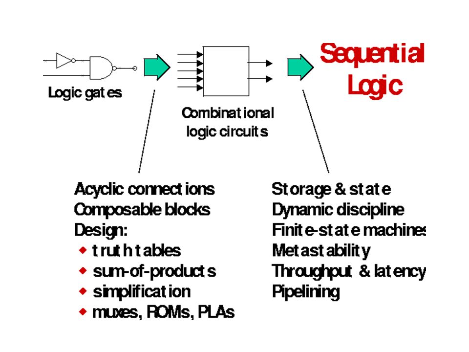
Sequential Circuits Problems(I) Prof. Sin-Min Lee Department of Mathematics and Computer Science Algorithm = Logic + Control

16
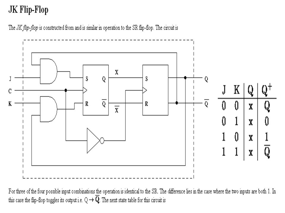
We wish to design a synchronous sequential circuit whose state diagram is shown in Figure. The type of flip-flop to be use is J-K Two flip-flops are needed to represent the four states and are designated Q0Q1. The input variable is labelled x.

17
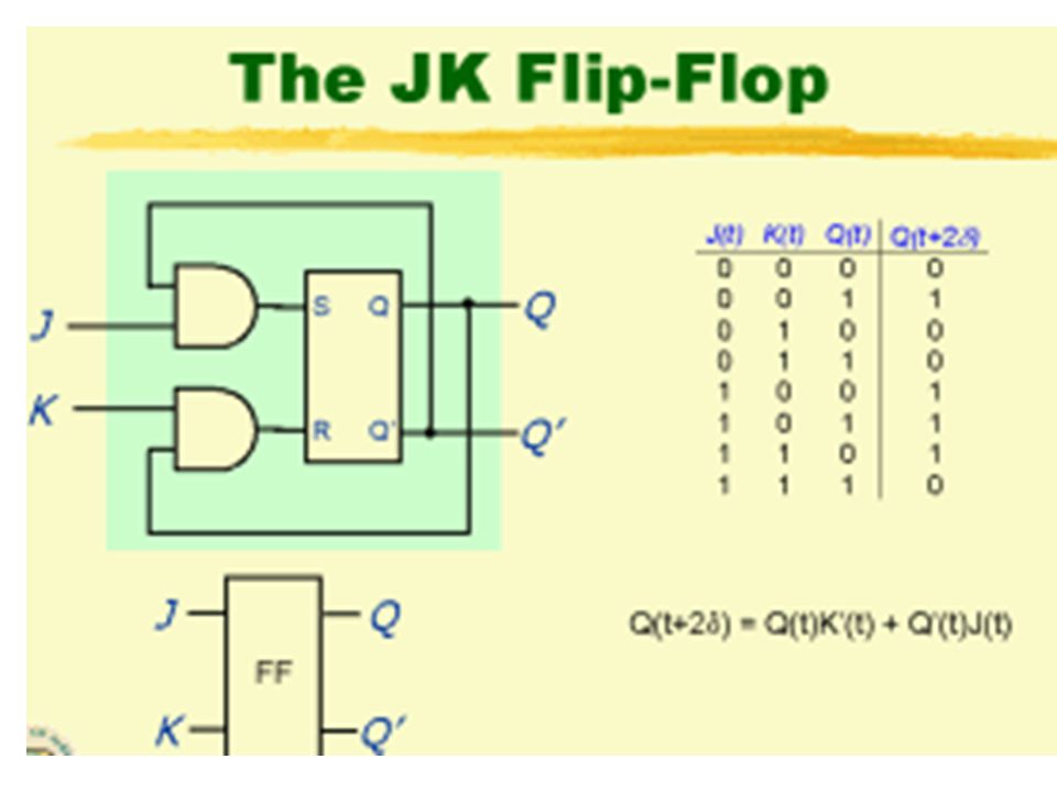
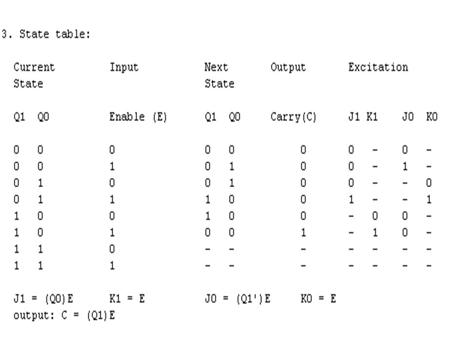
. Excitation table for JK flip-flop Excitation table of the circuit

18
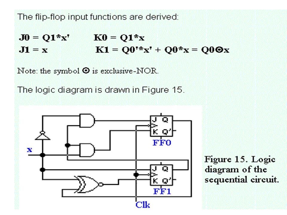
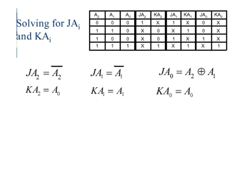
The simplified Boolean functions for the combinational circuit can now be derived

24
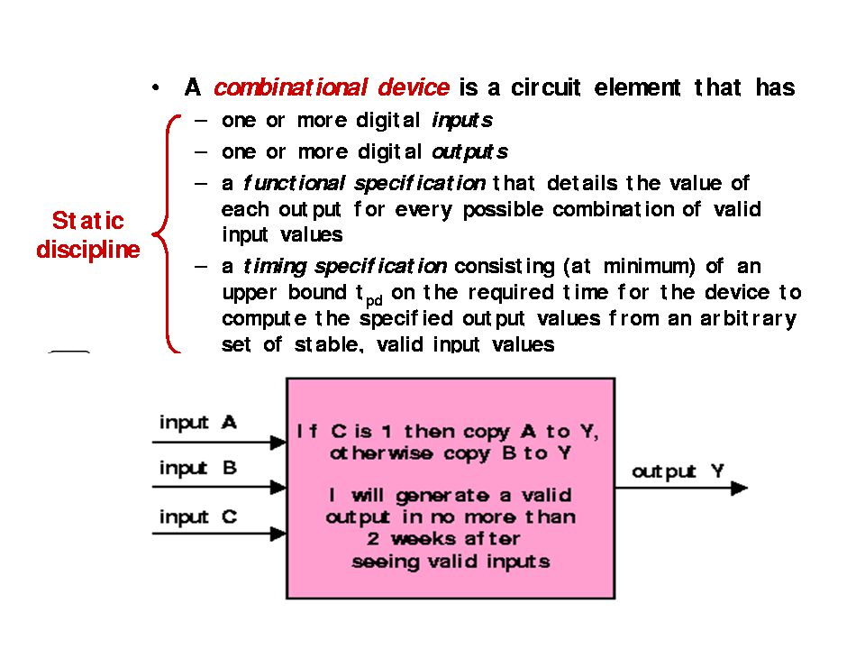
How do we determine the combinatorial ciccuit? This circuit has three inputs, I, R, and the current A. It has one output, DA, which is the desired next A. So we draw a truth table, as before. For convenience I added the label Next A to the DA column But this table is simply the truth table for the combinatorial circuit.

27
A divide-by-three counter which outputs one 1 for every 3 1's seen as input (not necessarily in succession.) After outputting a 1, it starts counting all over again. 1. To build this, will need three states, corresponding to 0, 1, or 2 1's seen so far.

29
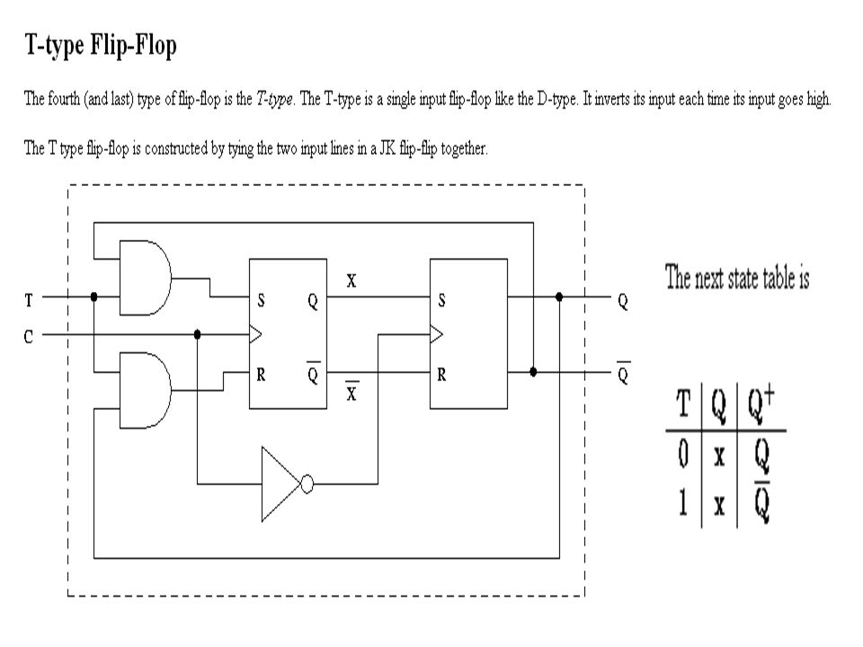
Designing with JK Flip-Flops The design of a sequential circuit with other than the D type is complicated by the fact that the flip- flop input equations for the circuit must be derived indirectly from the state table. When D-type flip- flops are employed, the input equations are obtained directly from the next state. This is not the case for JK and other types of flip-flops. In order to determine the input equations for these flip-flops, it is necessary to derive a functional relationship between the state table and the input equations.

30
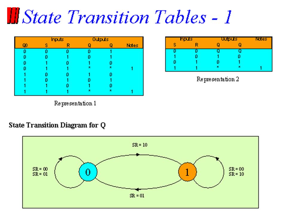
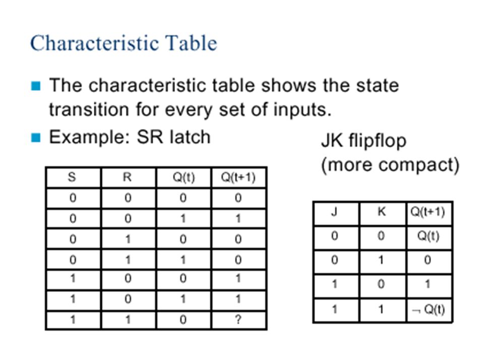
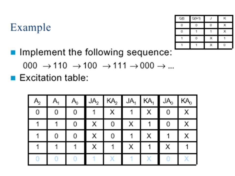
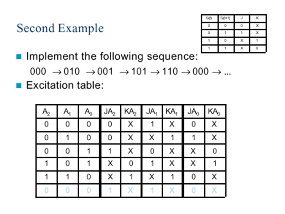
Flip-Flop Excitation Tables A table that lists the required inputs for a given change of state is known as an excitation table. Example of an excitation table is shown below:

31
Flip-Flop Excitation Tables (cont) The excitation table show four different types of flip-flops. Each table has a column for the present state Q(t), a column for the next state Q(t + 1), and a column for each flip-flop input to show how the required transition is achieved. The symbol X in the table represents a don’t-care condition, which means that it does not matter whether the input is 0 or 1.
, a column for the next state Q(t + 1), and a column for each flip-flop input to show how the required transition is achieved. The symbol X in the table represents a don’t-care condition, which means that it does not matter whether the input is 0 or 1..")
32
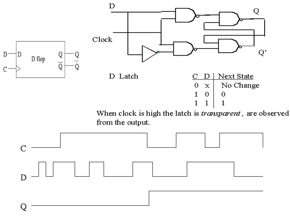
Flip-Flop Excitation Tables (cont) The excitation table for the D flip-flop shows that the next state is always equal to the D input and is independent of the present state. This can be represented algebraically: D = Q(t + 1)
.")
33
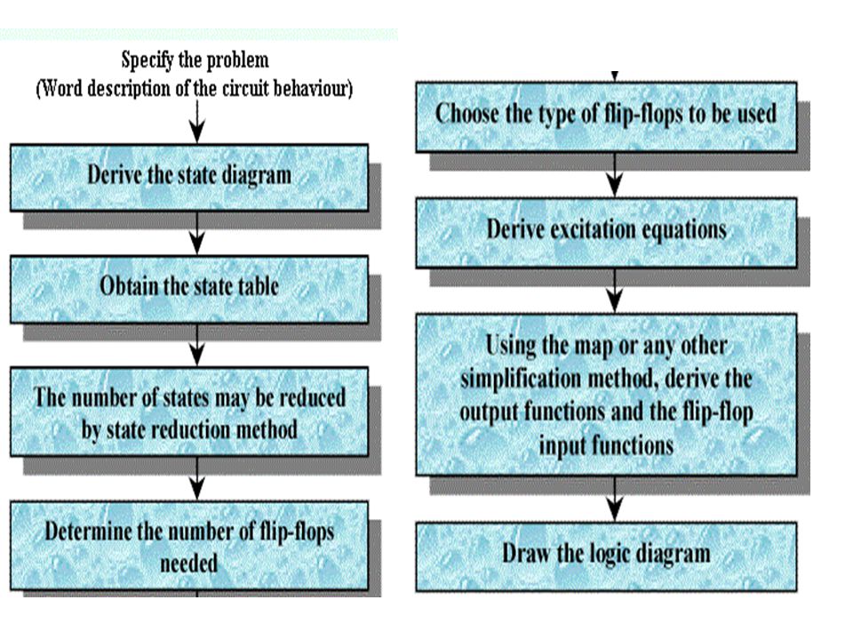
Design Procedure The design procedure for sequential circuits with JK flip-flops is the same as that for sequential circuits with D flip-flops, except that the input equations must be evaluated from the present-state to next-state transition derived from the excitation table.

34
Design Procedure (cont) The advantage of using JK-type flip-flops when designing sequential circuits is that there are so many don’t-care entries indicates that the combinational circuit for the input equations is likely to be simpler, because don’t-care minterms usually help in obtaining simpler expressions.
 The advantage of using JK-type flip-flops when designing sequential circuits is that there are so many don’t-care entries indicates that the combinational circuit for the input equations is likely to be simpler, because don’t-care minterms usually help in obtaining simpler expressions.")
35
Design Procedure (cont) In order to perform the simulation, a clock, as well as the input signals R and X, is required. In doing the simulation of any sequential circuit, sufficient time must be provided in the clock period for each of the following: 1. All flip-flops and inputs to change; 2. The effects of these changes to propagate through the combinational logic of the circuit to the flip-flop inputs; and 3. The setup of the flip-flops for the next clock edge to occur.

Similar presentations


 Lecture-8:>")


