Download presentation
Presentation is loading. Please wait.

2
Basic Concepts of Other Imaging Modalities Dent 5101

3
Body-section Radiography A special radiographic technique that blurs out the shadows of superimposed structures Object of interest less blurred Does not improve the sharpness

4
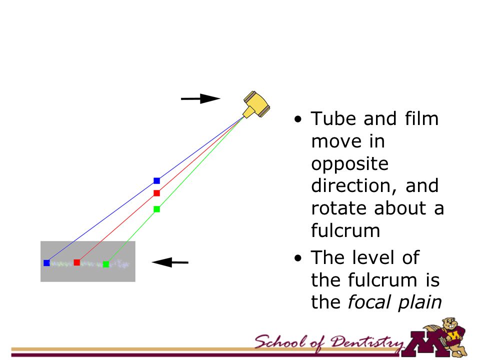
Tube and Film Move in Opposite Direction

6
Tube and film move in opposite direction, and rotate about a fulcrum The level of the fulcrum is the focal plain

7
Blurring Blurring Determined by: –Distance of the tube travel –Distance from the focal plain –Distance from the film –Orientation of tube travel

8
Panoramic Radiography

9
Obtained by rotating a narrow beam of radiation in the horizontal plane The film is rotated in the opposite direction while the object (jaws) is stationary
 is stationary")
11
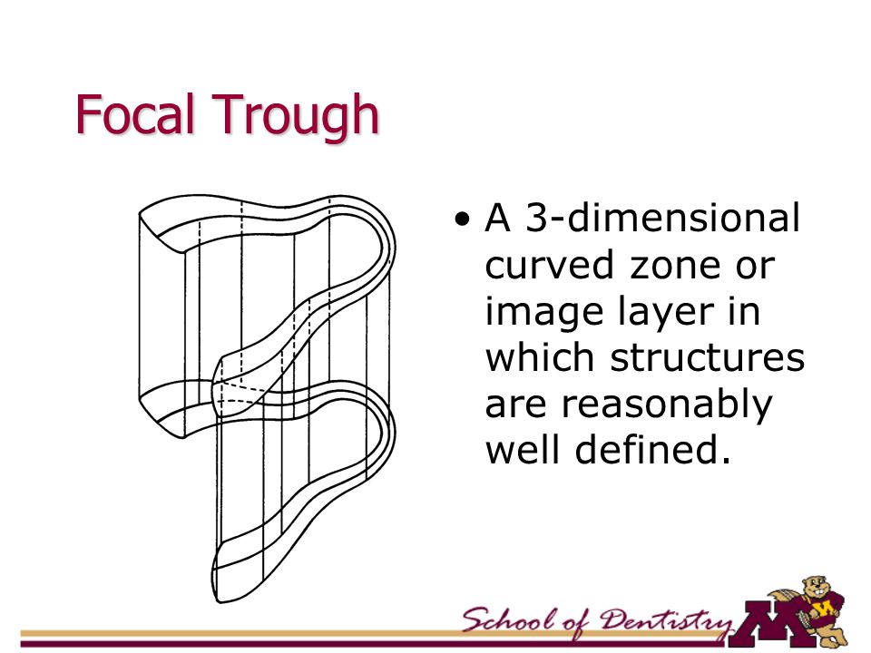
Focal Trough A 3-dimensional curved zone or image layer in which structures are reasonably well defined.

12
Types of Panoramic Machines Panorex – Two centers of rotation. Interruption of exposure in the midline Orthopantomogram – Three centers of rotation. Continuous image

13
Panorex Image

14
Orthopantpmograph

16
Image Intensification

17
Early Fluoroscopy Early fluoroscopy done by direct observation Screen was poorly illuminated - image perception inadequate

18
Image Intensification Image intensifier improved viewing of fluoroscopy

19
Intensifier Tube Four parts: –Input phosphor and photocathode –Electrostatic focusing lens –Accelerating anode –Output phosphor

20
Intensifier Tube (Cont.) Input phosphor: cesium iodide (CsI) or zinc- cadmium-sulfide. Photocathode: A photo-emissive metal. Electrostatic focusing lens: series of negatively charged electrodes—focuses the electron beam. Output phosphor: Provides thousand-fold more light photons.

21
Intensifier Tube Used in: –Sialography –Arthrography

22
Computed Tomography

23
Introduced in 70’s Principle: Internal structures of an object can be reconstructed from multiple projections of the object

24
Philips CTVision Secura

25
Mechanism of CT X-ray tube is rotated around the patient Radiation transmitted through the patient is absorbed by a ring of detectors Absorbed radiation is converted to an image Detectors

26
Detectors Scintillation crystals Xenon-gas ionization chamber

27
Scintillation Crystals Materials that produce light (scintillate) when x-rays interact Similar to intensifying screen Number of light photons produced energy ofincident x-ray beam Light photons need to be converted to electrical signal
 when x-rays interact Similar to intensifying screen Number of light photons produced energy ofincident x-ray beam Light photons need to be converted to electrical signal")
28
Ionization Chamber X-ray ionizes xenon gas Electrons move towards anode Generates small current Converted to electrical signal

29
Attenuation Reduction in the intensity of an x- ray beam as it traverses matter, by either the absorption or deflection of photons from the beam

30
Pixel - Voxel Pixel - picture element Voxel - volume element

31
CT Number Typical CT values TissuesRange (Hounsfield unit) Air-1000 Lung-200 to –500 Fat-50 to –200 Water0 Muscle+25 to +45 Bone+200 to +1000
 Air-1000 Lung-200 to –500 Fat-50 to –200 Water0 Muscle+25 to +45 Bone+200 to +1000")
32
Image Display: Windowing Usual CRT can display ~256 gray levels 2000 CT numbers Select the CT number of the tissue of interest, then range of ±128 shades

33
Cone Beam CT Uses cone shaped x- ray beam. Beam scans the head in 360 degrees. Raw data are reformatted to make images

36
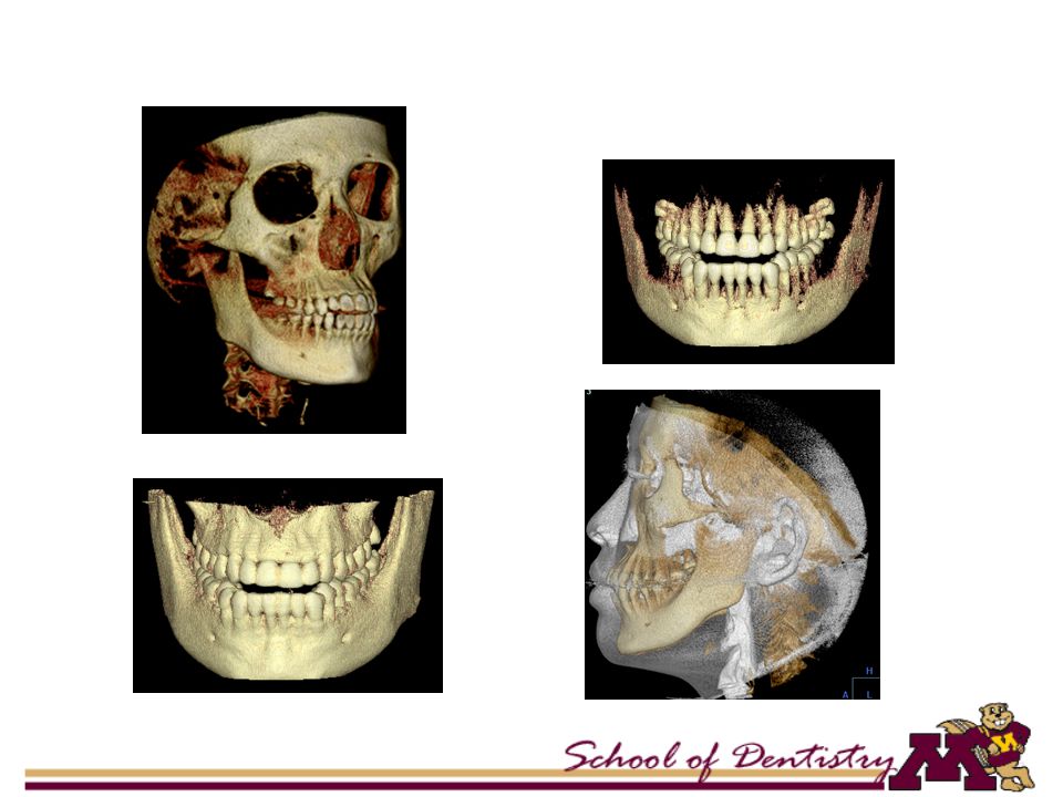
Benefits of Cone Beam Imaging Less radiation than multi-detector CT due to focused X-rays (less scatter) Fast and comfortable for the patient (9 to 60s) Procedure specific to head and neck applications One scan yields multiple 2D and 3D images
 Fast and comfortable for the patient (9 to 60s) Procedure specific to head and neck applications One scan yields multiple 2D and 3D images")
37
Anatomic Landmarks on CT

39
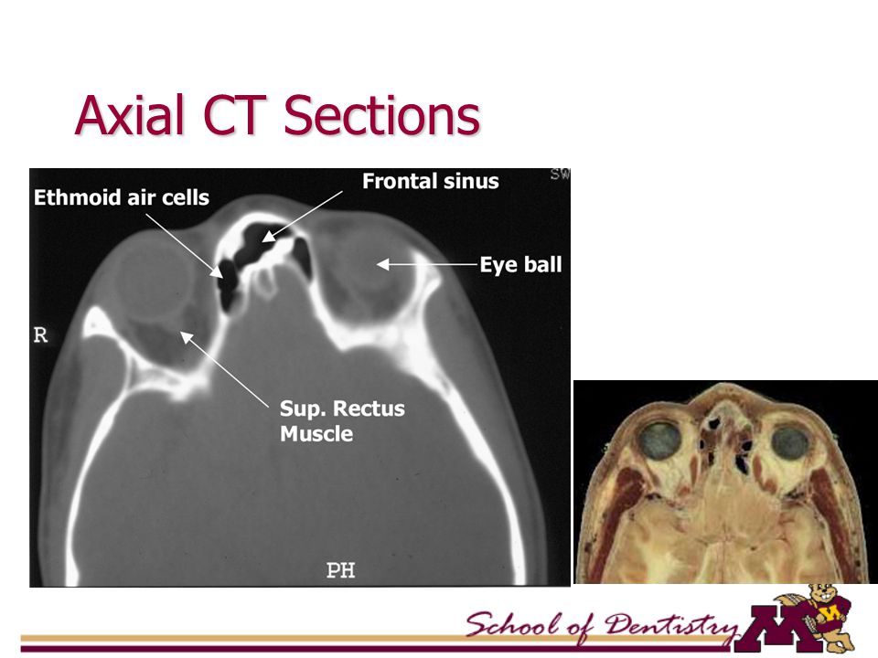
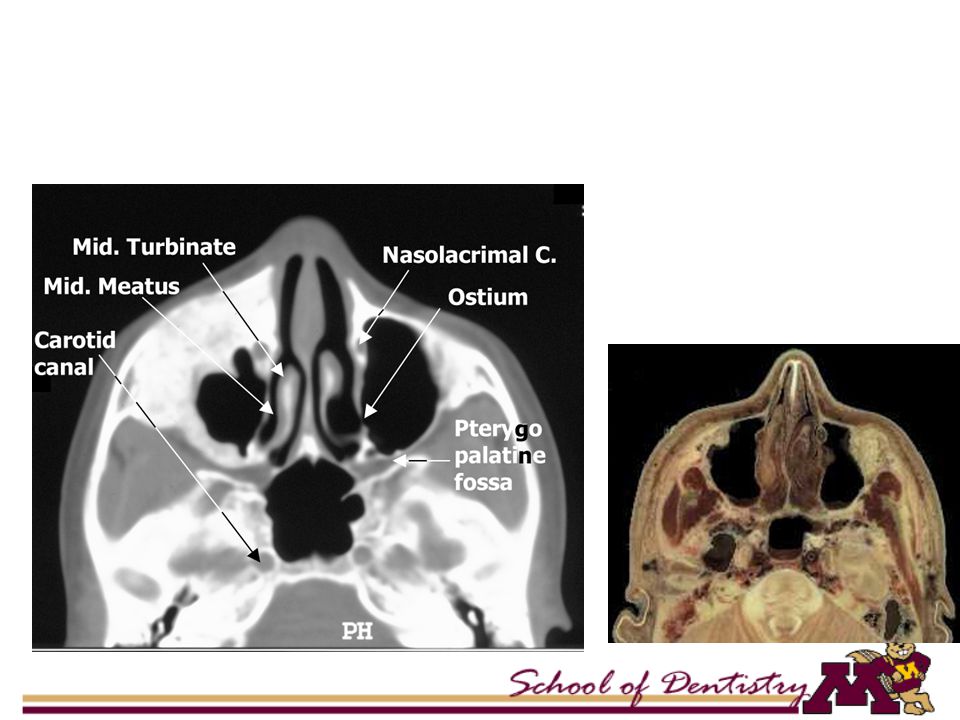
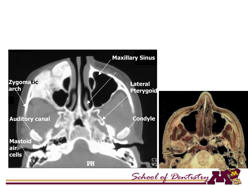
Axial CT Sections

43
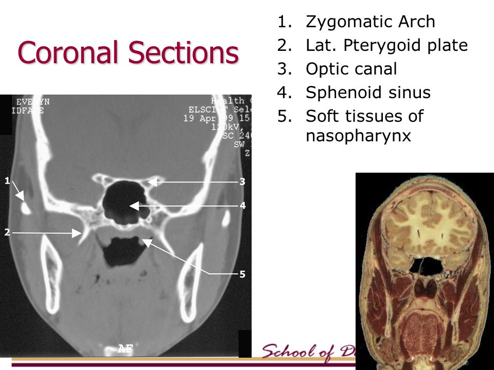
1.Zygomatic Arch 2.Lat. Pterygoid plate 3.Optic canal 4.Sphenoid sinus 5.Soft tissues of nasopharynx Coronal Sections

44
1.Frontal bone (orbital plate) 2.Ethmoid air cells 3.Middle concha 4.Maxillary sinus 5.Inferior concha
 2.Ethmoid air cells 3.Middle concha 4.Maxillary sinus 5.Inferior concha")
45
1.Vomer 2.Ramus 3.Follicle of molar 4.Gr. wing of Sphenoid 5.Tongue 6.Mylohyoid m

46
Magnetic Resonance Imaging

47
Three steps of MRI MRR –Magnetic Field –Radio-frequency Pulse –Relaxation

48
Magnetic Moment Direction

49
Application of RF Pulse Relaxation

50
Spin or Angular Moment 1 H, 14 N, 31 P, 13 C, and 23 Na has nuclear spin They spin around their axes similar to earth spinning around its axis Elements with nuclear spin has odd number of protons, neutrons

51
Magnetic Moment When a nucleus spins, it has angular momentum When the spinning nucleus has a charge, it has magnetic dipole moment Moving charges produce magnetic fields

52
Hydrogen Nucleus Most abundant Yields strongest MR signal

53
Radiofrequency Pulse RF pulse is an electromagnetic wave Caused by a brief application of an alternating electric current

54
Receiver Coils Send or “broadcast” the RF pulse Receive or “pick up” the MR signals Types: Body coils, head coils, and a variety of surface coils

55
Philips Gyroscan Intera

56
Relaxation This is the process that occurs after terminating the RF pulse The physical changes caused by the RF pulse revert back to original state

57
T1- Spin Lattice Relaxation At the end of RF pulse, transversely aligned nuclei tend to return back to equilibrium This return to equilibrium results in the transfer of energy

58
T2- Spin-spin Relaxation While the nuclei are in transverse phase, their magnetization interfere with each other. This interference leads to the loss of transverse magnetization.

59
Magnetic Field Strengths Measured in Tesla or Gauss Usual MRI field strength ranges from 0.5 to 2.0 Tesla Earth’s magnetic field is about 0.00005 Tesla (0.5 Gauss)
")
60
Advantages of MRI Higher resolution of tissues No ionizing radiation Multiplanar imaging

61
Disadvantages of MRI Long imaging time Hazards with ferromagnetic metals (pacemakers, vascular clips, etc) Claustrophobia Higher cost
 Claustrophobia Higher cost")
62
Relative Brightness of Tissues FatWhite Marrow Brain MuscleGray Body Fluid TMJ Disk Cortical Bone AirBlack

65
Nuclear Medicine

66
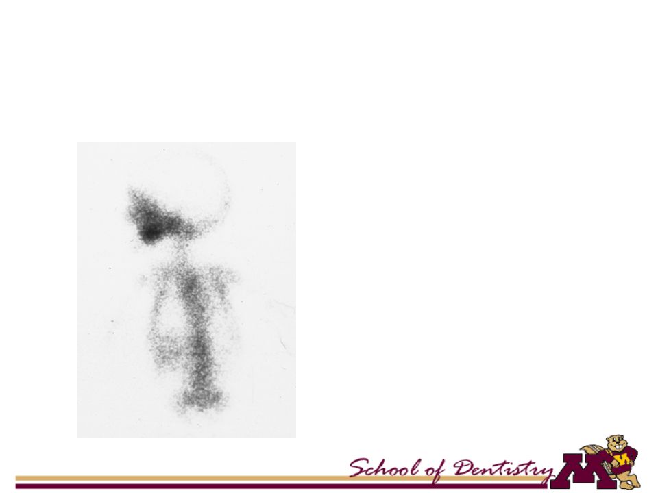
Radioactive compounds Target tissues Radioactive agents pools in the target tissues Detected and imaged by external detectors (gamma camera).
.")
67
Nuclear Medicine Shows structure and function of the target tissues Static and dynamic conditions Scintigraphy scans or RN (radionuclide) scans Bone scans or salivary gland scans
 scans Bone scans or salivary gland scans")
68
Technetium 99m TcO 4 - - thyroid and salivary gland scan 99 Tc phosphate - bone scan

69
Is this an active disease?

72
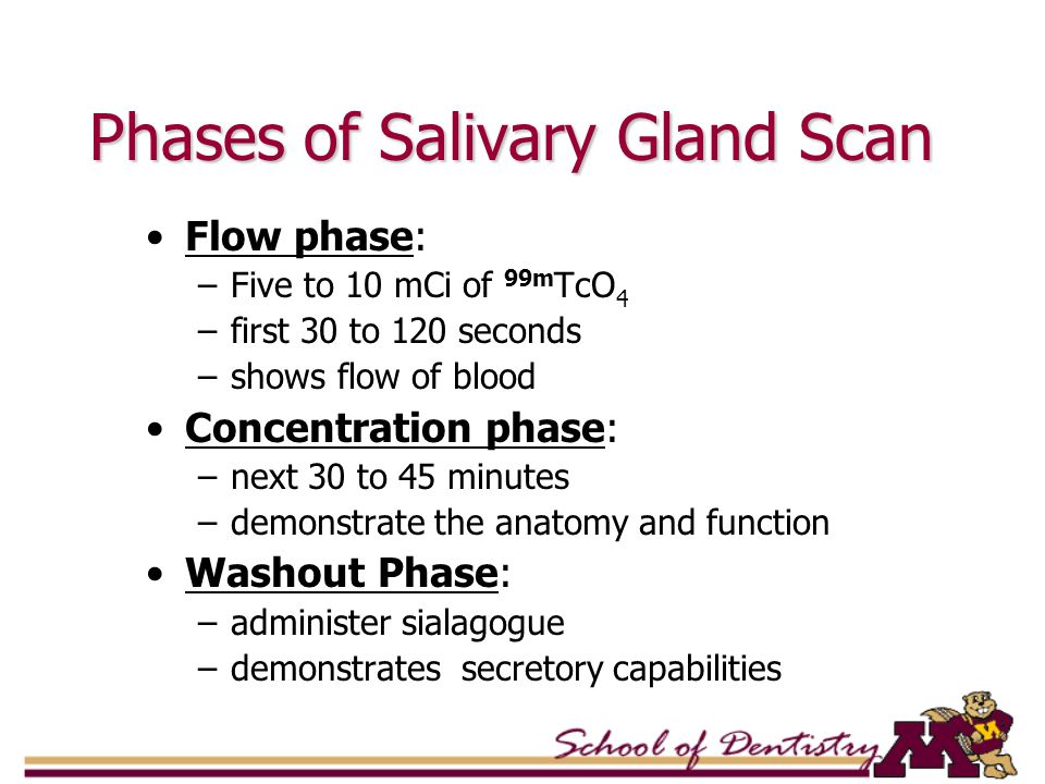
Phases of Salivary Gland Scan Flow phase: –Five to 10 mCi of 99m TcO 4 –first 30 to 120 seconds –shows flow of blood Concentration phase: –next 30 to 45 minutes –demonstrate the anatomy and function Washout Phase: –administer sialagogue –demonstrates secretory capabilities

73
Cephalometric Radiography Reproducible and standardized views For measurements and assess growth Fixed source to film distance – 60 inches Cephalostats and earplugs help in reproducible positions

74
Cephalometric Radiography

75
Contrast Agents

76
Radiopaque materials Water soluble Fat soluble 28 – 38% iodine

77
Phases of Sialography Ductal Acinar Evacuation

78
Indications of Sialography Acute swelling secondary to ductal obstruction Recurrent Inflammation Palpable salivary gland mass Autoimmune Sialadenitis

79
Contraindications of Sialography Sensitivity to contrast agents Acute Sialadenitis Limited use in tumor diagnosis

81
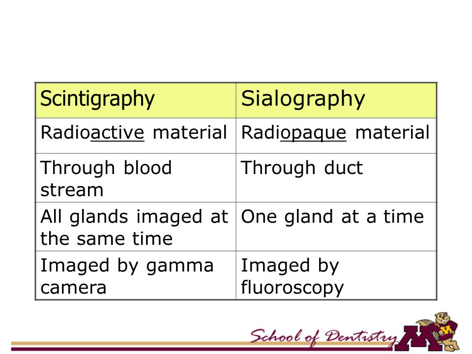
Scintigraphy Sialography Radioactive materialRadiopaque material Through blood stream Through duct All glands imaged at the same time One gland at a time Imaged by gamma camera Imaged by fluoroscopy

82
Contrast Studies: Arthrography

83
Arthrography Contrast media is introduced in joint spaces Upper vs. lower joint space Viewed by Image Intensifier Fluoroscopy Video recording allows study of joint movement

84
Contrast Material Injection

85
Open Position Translation of condyle Reduction of disk

Similar presentations


 – Introduction of medical imaging and MRI – Basic.>")
