Download presentation
Presentation is loading. Please wait.

1
Lecture 8: Atmosphere Transmission Petty Chapter 7

2
Atmospheric Transmission EM wave propagating through a homogeneous medium whose index of refraction N included a nonzero imaginary part. – ñ = n-ik Here, the real part of the refractive index n indicates the phase speed (snell’s law), while the imaginary part κ indicates the amount of absorption loss when the electromagnetic wave propagates through the material.absorption Intensity I falls off exponentially with distance: I λ (x) = I λ,0 exp (-β a x) where β a is an absorption coefficient that depend on the physical medium and wavelength.
, while the imaginary part κ indicates the amount of absorption loss when the electromagnetic wave propagates through the material.absorption Intensity I falls off exponentially with distance: I λ (x) = I λ,0 exp (-β a x) where β a is an absorption coefficient that depend on the physical medium and wavelength..")
3
n= sin i / sin r. (i: incident angle, r: the angle of refraction) Refractive index is also equal to the velocity c of light of a given wavelength in empty space divided by its velocity v in a substance, or n = c/v. REVIEW
 Refractive index is also equal to the velocity c of light of a given wavelength in empty space divided by its velocity v in a substance, or n = c/v. REVIEW.")
4
Review refractive indexdepend strongly upon the frequency of light. Standard refractive index measurements are taken at yellow doublet sodium D line, with a wavelength of 589 nanometres.refractive indexfrequencysodium D linewavelengthnanometres There are also weaker dependencies on temperature, pressure/stress,temperature pressurestress In general, an index of refraction is a complex number with both a real and imaginary part, where the latter indicates the strength of absorption loss at a particular wavelength—thus, the imaginary part is sometimes called the extinction coefficient k. Such losses become particularly significant, for example, in metals at short (e.g. visible) wavelengths, and must be included in any description of the refractive index.complex numberextinction coefficientrefractive index
 wavelengths, and must be included in any description of the refractive index.complex numberextinction coefficientrefractive index.")
5
Review Some typical refractive indices for yellow light (wavelength equal to 589 nanometres [10-9 metre]) are the following: air, 1.0002; water, 1.333 The refractive index of X-rays is slightly less than 1.0, which means that an X-ray entering a piece of glass from air will be bent away from the normal, unlike a ray of light, which will be bent toward the normal.X-rays
![Review Some typical refractive indices for yellow light (wavelength equal to 589 nanometres [10-9 metre]) are the following: air, ; water, The refractive index of X-rays is slightly less than 1.0, which means that an X-ray entering a piece of glass from air will be bent away from the normal, unlike a ray of light, which will be bent toward the normal.X-rays](http://images.slideplayer.com/16/5098815/slides/slide_5.jpg "Review Some typical refractive indices for yellow light (wavelength equal to 589 nanometres [10-9 metre]) are the following: air, ; water, The refractive index of X-rays is slightly less than 1.0, which means that an X-ray entering a piece of glass from air will be bent away from the normal, unlike a ray of light, which will be bent toward the normal.X-rays")
6
Snell’s LawReview Ni * Sin(Ai) = Nr * Sin(Ar), where: Ni is the refractive index of the medium the light is leaving, Ai is the incident angle between the light ray and the normal to the meduim to medium interface, Nr is the refractive index of the medium the light is entering, Ar is the refractive angle between the light ray and the normal to the meduim to medium interface.
 = Nr * Sin(Ar), where: Ni is the refractive index of the medium the light is leaving, Ai is the incident angle between the light ray and the normal to the meduim to medium interface, Nr is the refractive index of the medium the light is entering, Ar is the refractive angle between the light ray and the normal to the meduim to medium interface.")
7
Apply to atmosphere Fig. 7.1

8
Apply to atmosphere Interpretation of physical meaning of (7.1)
")
9
Apply to atmosphere

10
Radiative extinction using an overhead projection a b milk ink Absorption, Scattering

11
Radiative extinction using an overhead projection a b milk ink Milk –scattering Ink-absportion

12
Radiative extinction using an overhead projection a b milk ink I λ (x) = I λ,0 exp (-β e x)
 = I λ,0 exp (-β e x)")
13
Extinction, Scattering and Absorption Coefficients

14
Single scattering albedo

15
Extinction Over a Finite Path Fig. 7.3

16
Extinction Over a Finite Path Fig. 7.3 Beer’s Law

17
Extinction Over a Finite Path Fig. 7.3 Optical path Optical depth Optical thickness What is the dimension of TaoWhat is the range of Tao

18
Extinction Over a Finite Path Fig. 7.3 transmattance

19
Extinction Over a Finite Path Fig. 7.3

20
Extinction Over a Finite Path Fig. 7.3

21
Answer:

22
Ans (cont.)
")
23
Mass Extinction Coefficient

24
Answer:

25
Mass Extinction Coefficient

28
Extinction Cross-Section What is unit for δe?

29
Extinction Cross-Section ? 7.24

30
Generalization to Scattering and Absorption Single scattering albedo

31
Generalization to Arbitrary Mixtures of Components

32
Plane Parallel Approximation Fig. 7.4 Clouds?

33
Plane Parallel Approximation Fig. 7.4 Clouds?

34
Plane Parallel Approximation Fig. 7.4 - Definition

35
Plane Parallel Approximation Fig. 7.4 - Definition

36
Answer:

37
Optical Depth as Vertical Coordinate

39
Application to Meteorology, Climatology and Remote Sensing - The Transmission Spectrum of the Atmosphere

40
Application to Meteorology, Climatology and Remote Sensing - The Transmission Spectrum of the Atmosphere CO 2, Mauna Loa Observatory, Hawaii The “Keeling curve,” a long-term record of atmospheric CO2 concentration measured at the Mauna Loa Observatory (Keeling et al.). Although the annual oscillations represent natural, seasonal variations, the long-term increase means that concentrations are higher than they have been in 400,000 years.

41
Application to Meteorology, Climatology and Remote Sensing - The Transmission Spectrum of the Atmosphere

42
Fig. 7.6

43
Fig. 7.7

44
Scattering by Clear Air Fig. 7.8 1 λ4λ4

45
Extinction and Scattering by Aerosols and Clouds

48
Measuring Solar Intensity from the Ground Fig. 9 Why?

49
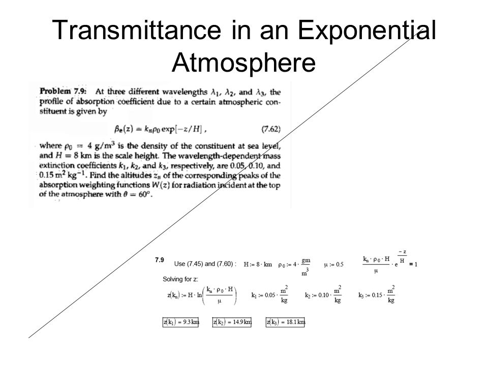
Transmittance in an Exponential Atmosphere

50
Transmittance in an Exponential Atmosphere _

51
Transmittance in an Exponential Atmosphere

52
Fig. 7.10

53
Transmittance in an Exponential Atmosphere Fig. 7.10

54
Transmittance in an Exponential Atmosphere

56
Optical thickness and Transmittance of a Cloud Layer

60
Monodisperse Cloud Fig. 7.11

61
Optical thickness and Transmittance of a Cloud Layer Monodisperse Cloud

65
Optical thickness and Transmittance of a Cloud Layer Cloud Condensation Nuclei and Cloud Optical Depth

69
Optical thickness and Transmittance of a Cloud Layer Polydisperse Cloud

Similar presentations


 Lecture 12.>")


>")


 Analytical Mineralogy Part 1: Nature of Light Introduction to Optical Mineralogy.>")


 … index of refraction Index of refraction Absorption.>")


>")
