Download presentation
Presentation is loading. Please wait.

2
QUALITY FUNCTION DEPLOYMENT CHAPTER 12
TEC 5133 Al Williams & Steve Whisnant

5
QFD DEFINED A method for developing a design quality aimed at satisfying the consumer and then translating the consumer’s demands into design targets and major quality assurance points to be used throughout the production phase.

6
FOUNDER Dr. Mizuno, professor emeritus of the Tokyo Institute of Technology, is credited with initiating the quality function deployment (QFD) system. The first application of QFD was at Mitsubishi, Heavy Industries, Ltd., in the Kobe Shipyard, Japan, in 1972
 system. The first application of QFD was at Mitsubishi, Heavy Industries, Ltd., in the Kobe Shipyard, Japan, in")
7
BENEFITS An organization that correctly implements QFD can improve engineering knowledge, productivity, and quality and reduce costs, product development time, and engineering changes.

8
They want it WHEN!!!

9
QFD Quality function deployment begins with marketing to determine what exactly the customer desires from a product. During the collection of information, the QFD team must continually ask and answer numerous questions, such as?

10
QFD TEAM What does the customer really want?
What are the customer’s expectations? Are the customer’s expectations used to drive the design process? What can the design team do to achieve customer satisfaction?

11
WAYS TO GATHER INFORMATION
Focus groups Compliant reports Gov. Regulations Law suits Hot lines Surveys Customer tests Preferred customers Org. Standards Trade visits Customer visits Consultants Sales force Training Trade shows Vendors Suppliers Employees

12
THE QFD TEAM There are two types of teams: New product design
Improving an existing product Teams are composed of members from marketing, design, quality, finance, and production.

13
THE QFD TEAM Time and inter-team communications are two very important things that each team must utilize to their fullest potential. Using time effectively is the essential resource in getting the project done on schedule. Using inter-team communication to its fullest extent will alleviate unforeseen problems and make the project run smoothly.

14
TECHNIQUES Identify the customer Determining customer requirements
Prioritizing the requirements Competition benchmarking Translating the customer requirements into measurable engineering requirements Setting engineering targets for design

15
FOUR BENEFITS OF QFD Improves customer satisfaction
Reduces implementation time Promotes teamwork Provides Documentation

16
IMPROVES CUSTOMER SATISFACTION
Quality function deployment looks past the usual customer response and attempts to define the requirements in a set of basic needs, which are compared to all competitive information.

17
REDUCES IMPLEMENTATION TIME
Fewer engineering changes are needed when using QFD, and, when used properly, all conflicting design requirements can be identified and addressed prior to production.

18
PROMOTES TEAMWORK QFD forces a horizontal deployment of communication channels. Inputs are required from all facets of an organization, from marketing to production to sales, thus ensuring that the voice of the customer is being heard and that each department knows what the other is doing.

19
PROVIDES DOCUMENTATION
A data base for future design or process improvements in created. Data that are historically scattered within operations, frequently lost and often referenced out of context, are now saved in an orderly manner to serve future needs.

20
FOUR IMPORTANT POINTS TO UNDERSTAND BEFORE IMPLEMENTATION OF QFD
No matter how well the design team thinks it understands the problem, it should employ the QFD method for all design projects. In the process the team will learn what it doesn’t know about the problem. The QFD method can be applied to the entire problem and/or any subproblem

21
IMPORTANT POINTS CONT. The customer’s requirements must be translated into measurable design targets. You can’t design a car door that is “easy to open” when you don’t know the meaning of the word “easy”. It is important to worry about what needs to be designed, only after this is fully understood, to worry about how the design will look and work

22
AFFINITY DIAGRAM A team of six to eight members should be adequate to assimilate all of the thoughts. Constructing an affinity diagram requires four simple steps:

23
AFFINITY DIAGRAM Phrase the objective Record all responses
Group the responses Organize groups in an affinity diagram THE AFFINITY DIAGRAM IS DISCUSSED MORE IN CHAPTER 17. IT IS A TOOL THAT GATHERS A LARGE AMOUNT OF DATA AND SUBSEQUENTLY ORGANIZES THE DATA INTO GROUPINGS BASED ON THEIR NATURAL INTERRELATIONSHIPS. OTHER METHODS THAT ARE IDEAL FOR ORGANIZING LARGE AMOUNTS OF INFORMATION ARE “INTERELATIONSHIP DIAGRAMS” … ”TREE DIAGRAMS” … “ CAUSE AND EFFECT DIAGRAMS”.

24
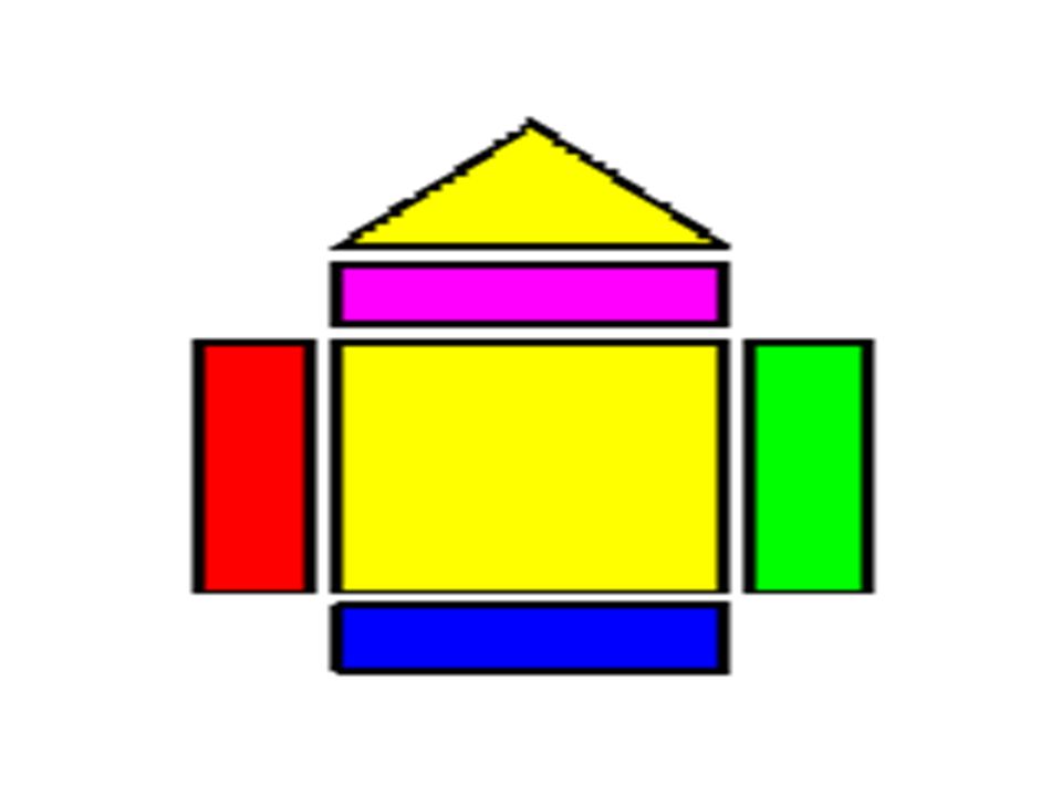
The exterior walls of the house are the customer requirements.
On the left side is a listing of the voice of the customer, or what the customer expects in the product. On the right side are the prioritized customer requirements, or planning matrix. Listed are items such as customer benchmarking, customer importance rating, target value, scale-up factor, and sales point. The ceiling, or second floor, of the house contains the technical descriptors. Consistency of the product is provided through engineering characteristics, design constraints, and parameters. The interior walls of the house are the relationships between customer requirements and technical descriptors. Customer expectations (customer requirements” are translated into engineering characteristics (technical descriptors). The roof of the house is the interrelationship between technical descriptors. Trade offs between similar and/or conflicting technical descriptors are identified. The foundation of the house is the prioritized technical descriptors. Items such as the technical benchmarking, degree of technical difficulty, and target value are listed.
. The roof of the house is the interrelationship between technical descriptors. Trade offs between similar and/or conflicting technical descriptors are identified. The foundation of the house is the prioritized technical descriptors. Items such as the technical benchmarking, degree of technical difficulty, and target value are listed.")
25
INTERRELATIONSHIPS RELATIONSHIP REQUIREMENTS AND DESCRIPTORS

26
INTERRELATIONSHIPS Illustrated the QFD team’s perceptions of interrelationships between technical and customer requirements. An appropriate scale is applied, illustrated using symbols or figures.

27
TECHNICAL REQUIREMENTS VOICE OF THE ORGANIZATION

28
TECHNICAL REQUIREMENTS
What’s??? A structured set of relevant and measurable product characteristics.

29
TECHNICAL REQUIREMENTS
INTERRELATIONSHIPS

30
ROOF

31
ROOF Interrelationship between technical descriptors. Used to identify where technical requirements support or impede each other in the product design. Can highlight innovation opportunities.

32
TECHNICAL REQUIREMENTS
ROOF TECHNICAL REQUIREMENTS INTERRELATIONSHIPS

33
Prioritized technical descriptors
TARGETS Prioritized technical descriptors

34
TARGETS Used to record the priorities assigned to technical requirements by the matrix, measures of technical performance achieved by competitive products and the degree of difficulty involved in developing each requirements.

35
TECHNICAL REQUIREMTNTS
ROOF TECHNICAL REQUIREMTNTS INTERRELATIONSHIPS TARGETS

36
REQUIREMENTS CUSTOMER

37
CUSTOMER REQUIREMENTS
How’s??? A structured list of requirements derived from customer statements.

38
TECHNICAL REQUIREMTNTS
ROOF TECHNICAL REQUIREMTNTS REQUIREMENTS CUSTOMER INTERRELATIONSHIPS TARGETS

39
PLANNING MATRIX

40
PLANNING MATRIX Prioritized customer requirements. Illustrates customer perceptions observed in market surveys. Includes relative importance of customer requirements, company and competitor performance in meeting these requirements.

41
TECHNICAL REQUIREMTNTS
ROOF TECHNICAL REQUIREMTNTS REQUIREMENTS CUSTOMER INTERRELATIONSHIPS PLANNING MATRIX TARGETS

43
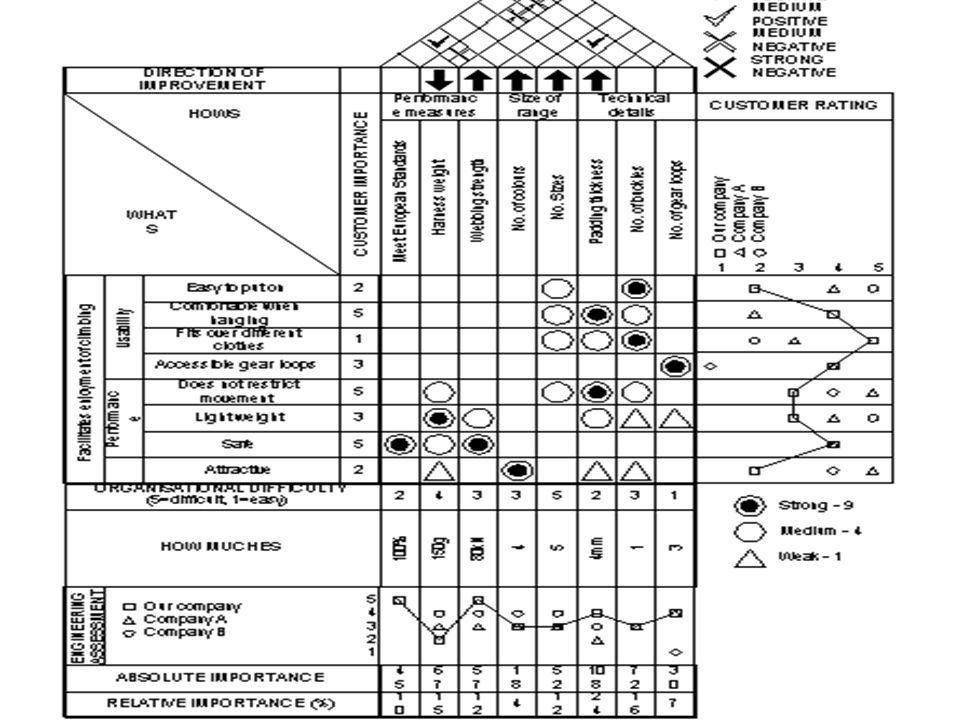
HOUSE OF QUALITY As a company builds the House of Quality, it hopes to accomplish several things: Evaluate its product or services versus its competition of a given target Identify customer requirements that are not being met Identify technical requirements that are not related to customer requirements, and may be superfluous. Identify key technical requirements, and Develop an initial strategy for improvement

44
CONCLUSION An orderly way of obtaining information and presenting it
Shorter product development cycle Considerably reduced start-up costs Fewer engineering changes

45
CONCLUSION CONT. Reduced chance of oversights during the design process An environment of teamwork Consensus decisions Everything is preserved in writing

46
EIU THANK YOU STEVE QUESTIONS ???? AL HAVE A GREAT SUMMER

Similar presentations


>")


 Right side Prioritized customer requirement Planning matrix Left side Voice.>")


>")
>")


 Joseph Appianing Dan Sheehan Matt Casey October 29,2008.>")
