Download presentation
Presentation is loading. Please wait.

1
Tension Members Structural Elements Subjected to Axial Tensile Forces Cables in Suspension and Cable-Stayed Bridges Trusses Bracing for Buildings and Bridges

2
TENSION MEMBERS - TYPES Wire Ropes and Cables Suspension Bridges, Prestressed Concrete, Guyed towers etc. Strand: wires laid helically about a center Rope: strands laid helically around a central core (fabric or strand) Cable: one or more groups of wires, strands or ropes
 Cable: one or more groups of wires, strands or ropes.")
3
TENSION MEMBERS - TYPES Rods and Bars Square or Round Rod Difficult to connect to other members Occasional use today - bracing Good practice to produce initial tension to reduce rattling and swaying Bars: Usually rectangular plates eyebars welded bolted Special situations to transfer tensile load from a wire, rope or cable to an assemblage or anchorage

4
Tension Members - Types

5
TENSION MEMBERS - TYPES Structural Shapes & Build Up Members rigidity, small lateral loads, load reversal Slenderness L/r > 300 AISC Spec D1 Does not apply to rods in tension

6
TENSION MEMBERS - LIMIT STATES

8
Limit States STRENGTH Failure at Main Body Failure at Connection etc

9
Tensile Strength Failure in Main Body Failure at Connection AgAg AeAe

10
TENSION MEMBERS - LIMIT STATES AISC Specs Chapter D Failure at main body if connection is strong enough After yielding deformations become too large and member does not serve its design purpose. Failure at yielding nominal strength P n =F y A g F y = Yielding Strength, A g = Gross Area

11
TENSION MEMBERS - LIMIT STATES AISC Specs Chapter D Failure at Connection if connection is weak it will fracture Failure at ultimate strength nominal strength P n =F u A e F u = Ultimate Strength, A e = Effective Area

12
Gross Area – Specs D3.1 p 16.1.27 Gross Area A g : Total Area of Main Body of Member

13
Net Area – Specs D3.2 p 16.1.27 Net Area A n : Welded Connections A n = A g Bolded Connections A n = A g - Area of Holes

14
Net Area Size of hole is larger than size of the bolt d h =d b +1/16” Additional 1/16” of material is damaged during drilling or punchning of holes (Commentary D3.2 p 16.1-250)
")
15
Net Area – Example (Assume A n =A e ) PL 3/4x10 Bolts 3/4 2 2 3 2 1/4 Based on YieldingBased on Fracture
 PL 3/4x10 Bolts 3/ /4 Based on YieldingBased on Fracture")
16
Net Area – Example (Assume A n =A e ) Based on Yielding Based on Fracture LRFD-Design Strength Yielding Fracture ASD-Design Strength Yielding Fracture
 Based on Yielding Based on Fracture LRFD-Design Strength Yielding Fracture ASD-Design Strength Yielding Fracture")
17
Net Area – Example (Assume A e =0.85A n ) D=35 kips L=15 kips Investigate Compliance with AISC Specs
 D=35 kips L=15 kips Investigate Compliance with AISC Specs")
18
Net Area – Example (Assume A e =0.85A n ) Based on YieldingBased on Fracture Nominal Strength P n
 Based on YieldingBased on Fracture Nominal Strength P n")
19
Net Area – Example (Assume A e =0.85A n ) Yielding Fracture LRFD CapacityDemand Yielding Fracture Combination 1 Combination 2 Lowest GOVERNSHighest GOVERNS
 Yielding Fracture LRFD CapacityDemand Yielding Fracture Combination 1 Combination 2 Lowest GOVERNSHighest GOVERNS")
20
Net Area – Example (Assume A e =0.85A n ) Yielding Fracture ASD CapacityDemand Yielding Fracture Combination 1 Combination 2 Lowest GOVERNSHighest GOVERNS
 Yielding Fracture ASD CapacityDemand Yielding Fracture Combination 1 Combination 2 Lowest GOVERNSHighest GOVERNS")
21
Staggered Fasteners Space Limitations Geometry Constraints

22
Staggered Fasteners Inclined Fracture Path

23
Net Area - Effect of Staggered Holes AISC Specs D3.1 TT T T Failure paths on net section g s p g = gage s = spacing Reduced diameter

24
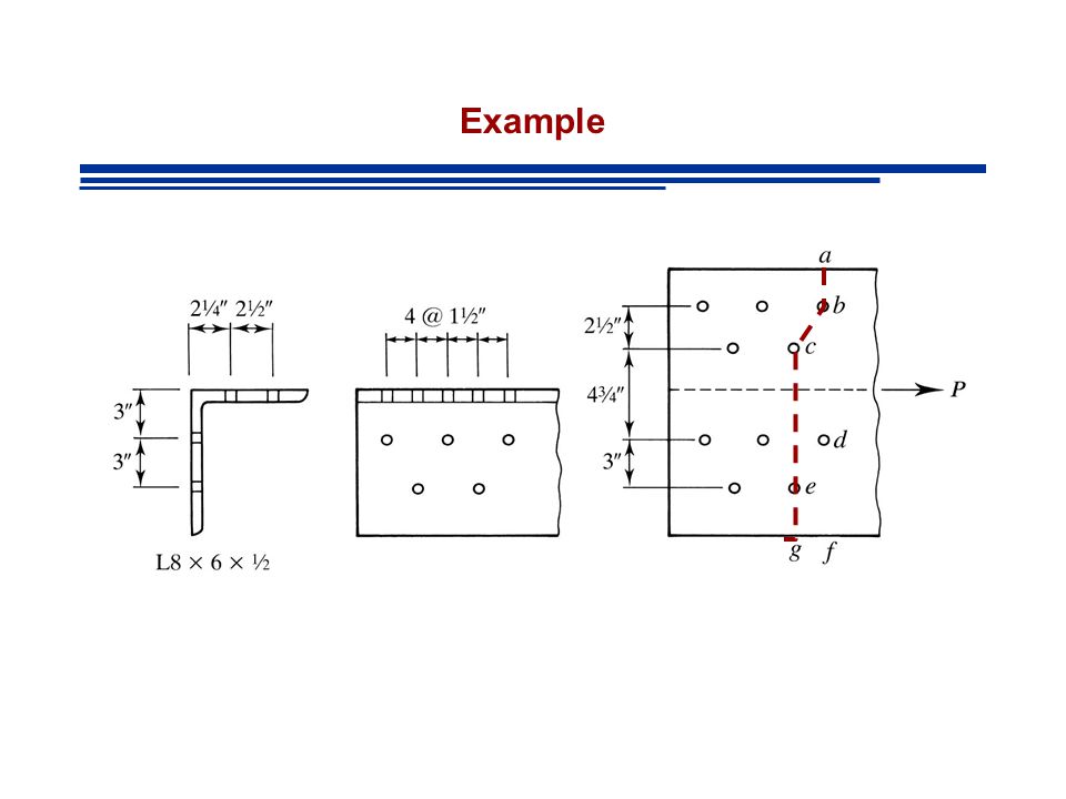
Example d=1”

25
Example

26
Smallest w n Controls

27
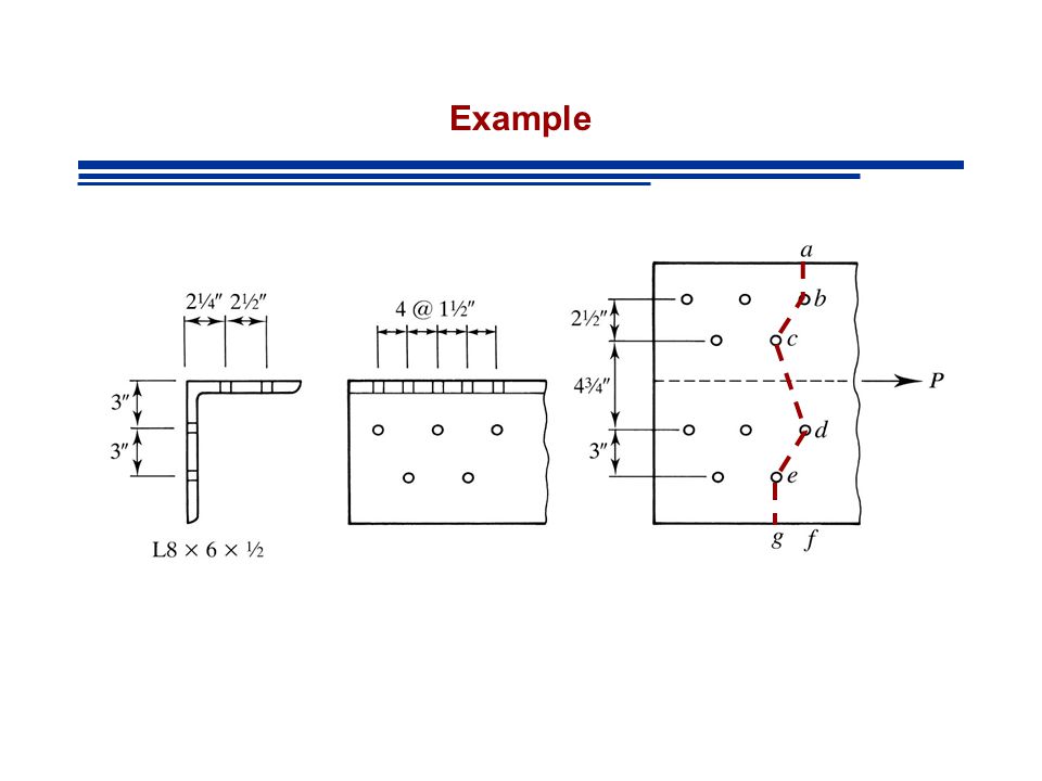
Example

28
Different failure lines may be subjected to different loads! 11 holes 8/11 of load

29
Net Area - Gage Distance for an Angle Unfold Angle and Visualize as a plate

30
Net Area - Gage Distance for an Angle

31
Example

34
HOMEWORK Study Examples 3.1-3.9 Homework 3.2-1, 3.2-3, 3.4-2, 3.4-4

35
Effective Net Area – Specs D3.3 p 16.1.28 A e =AU A = Area that depends on type of connection U = shear lag coefficient (accounts for eccentricities)
")
Similar presentations

 BEAM- COLUMNS SHEAR / CONC. LOADS>")


>")


