Download presentation
Presentation is loading. Please wait.

1
ATMOSPHERIC OBSERVATIONS S.K. Satheesh Centre for Atmospheric & Oceanic Sciences Indian Institute of Science Bangalore.

2
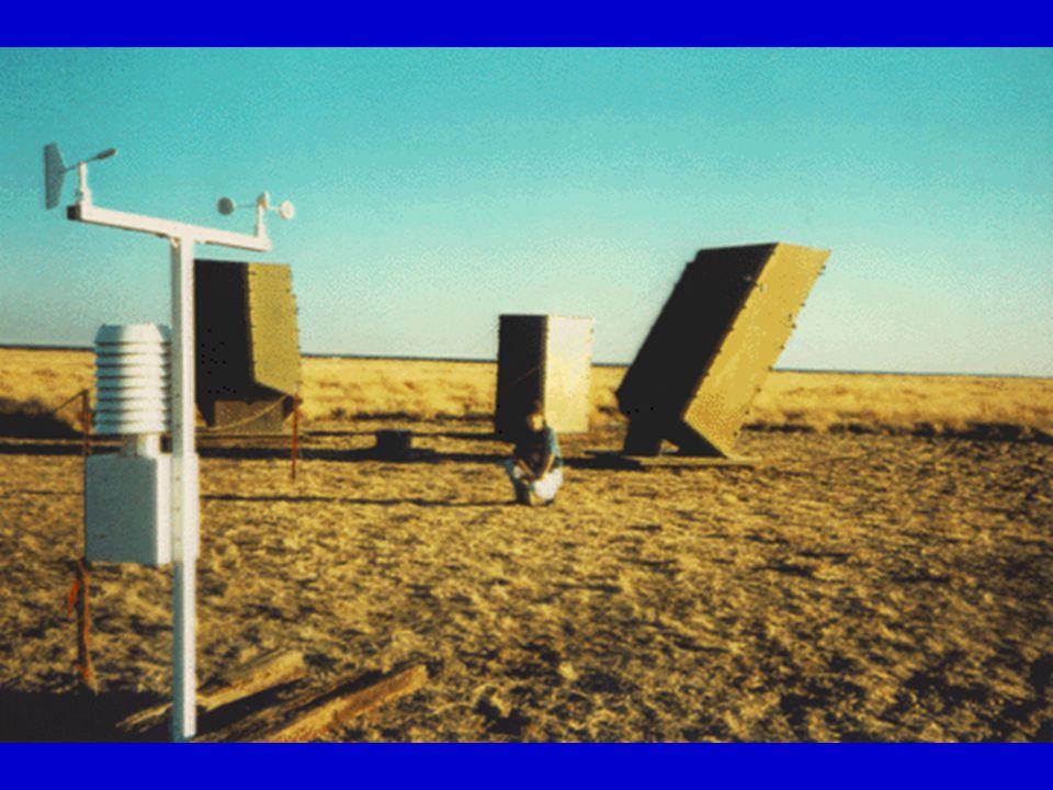
METEOROLOGICAL MEASUREMENTS (Temperature, RH, Pressure, Rainfall, Wind) RADIATION MEASUREMENTS (Direct, Diffuse and Spectral Flux) POLLUTANT MEASUREMENTS (Aerosols) CLOUDS AND WEATHER (Cloud base height, Cloud droplet concentration, Detection of weather systems) UPPER AIR OBSERVATIONS (Radio sonde)
 RADIATION MEASUREMENTS (Direct, Diffuse and Spectral Flux) POLLUTANT MEASUREMENTS (Aerosols) CLOUDS AND WEATHER (Cloud base height, Cloud droplet concentration, Detection of weather systems) UPPER AIR OBSERVATIONS (Radio sonde)")
3
Physical PhenomenaTransducers A Typical Measurement System Signal Conditioning Data Acquisition PC

4
Part-1: METEOROLOGICAL MEASUREMENTS Infrared Temperature Sensor Mechanical and Electronic Thermometers TEMPERATURE Measurements Thermistor

5
Mechanical Thermometers Bi-metallic strip Liquid-in-glass thermometer

6
Electronic Thermometers Thermo couples Principle: Thermoelectric effect The thermoelectric potential can be expressed as a non-linear function of temperature as, where , ,..etc. are constants depends on the materials used, T is the temperature of the measuring junction, and temperature of the cold junction (reference junction) is kept at 0 C. Hot junction Cold junction E = T + T 2 + ……..
 is kept at 0 C. Hot junction Cold junction E = T + T 2 + ……...")
7
Thermistors Principle: Large negative resistance coefficient. An increase in T by 1 C yields a 5% decrease in resistance. The relation between electric resistance and temperature is given by, where R(T) is resistance at T, R(T 0 ) is resistance at T 0, B is a constant depending on the material. R(T) = R(T 0 ) exp[B(1/T-1/T 0 )
 is resistance at T, R(T 0 ) is resistance at T 0, B is a constant depending on the material. R(T) = R(T 0 ) exp[B(1/T-1/T 0 ).")
8
Infrared temperature sensor UNIT: C

9
Hygrometer or Psychrometer HUMIDITY Measurements RH = water content / water capacity at a given temperature Mechanical and Electronic

10
Electronic Humidity Sensors Electronic humidity sensors operate based on a capacitance change of a polymer thin film capacitor. Absorption of water vapour by the polymer alters its capacitance. It responds to a 90% humidity change in less than 1 second with accuracy of 1%. Advantages: Suitable for aircraft and radio sonde measurements.

11
UNIT: Expressed in %

12
Typical Variation of Temperature and RH within a day Noon

13
PRESSURE Sensor Mechanical and Electronic h Mercury barometer Principle: The weight of the mercury column is balanced by the pressure exerted on the dish of mercury by the air above. If pressure decreases, the column of mercury falls, if pressure increases, the column of mercury will be more. Disadvantages: Mercury barometer is highly inconvenient for mobile platforms such as aircraft, radiosonde etc. and its response is slow.

14
Electronic Pressure Sensors They are liquid-free and called aneroid barometers. This is a thin metal membrane that deforms in response to changes in external pressure. Usually a partially evacuated chamber is used. The chamber compresses as pressure increases and expand as pressure decreases. UNIT: mb or KPa

15
RAIN Sensor Rain Gauge, Tipping bucket and Optical Rain sensors Rain Gauges

16
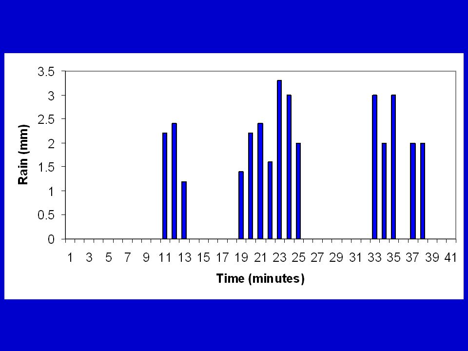
Tipping bucket

17
Optical Rain Sensors diode laser Photodiode detector

19
WIND Sensors Cup anemometer Gill anemometer Sonic anemometer

20
Anemometry: The science of measuring and recording wind field is called anemometry. The term ‘wind field’ represents both wind speed and wind direction. The speed is expressed in m/s and direction is specified relative to North at the palce of observation and is expressed in degrees. N E S W North 0 East 90 South 180 West 270

21
Anemometric devices are mainly three (1) Mechanical (2) Thermodynamical and (3) Electronic. Cup and Gill Anemometers Principle: A steady wind speed, u, causes a corresponding Cup speed, U. Wind speed and Cup speed are related by the power series expression, where a, b, c, … are calibration coefficients. Usually, the coefficients of U 2 and higher powered terms of U are zero. Advantages: Low cost Disadvantages: Mechanical degradation (friction), presence of moving parts not favorable for long term operation, Response is slow. U = a + bU + cU 2 + …….
, presence of moving parts not favorable for long term operation, Response is slow. U = a + bU + cU 2 + ……..")
22
AB Wind Direction

23
Hotwire Anemometers Principle: Works on the principle that a given increase in wind speed enhances the heat transfer to the environment, which in turn decreases the temperature and resistance of the wire. The resistance decrease cause a change in current which is measure of wind speed. Advantages: Low cost Disadvantages: Response is slow. Typical Hot-Wire Anemometer

24
Sonic Anemometers Principle: Operation is based on the interference in the frequency of sound pulses sent across short path length due to the wind. The time difference, t, between the initial transmission of sound pulses across the air stream and their reception is a direct function of mean air speed along the path. l = path length = angle of wind (with speed u) with respect to sound wave (with speed c) Advantages: Inertia-free, best for long term operations, no moving parts, very slow and very high winds (0.03 to 50 m/s) can be measured. Best for air craft measurements. Disadvantages: Very expensive. t = 2 l u cos( ) [c 2 -u 2 ] -1
 with respect to sound wave (with speed c) Advantages: Inertia-free, best for long term operations, no moving parts, very slow and very high winds (0.03 to 50 m/s) can be measured. Best for air craft measurements. Disadvantages: Very expensive. t = 2 l u cos( ) [c 2 -u 2 ] -1.")
25
Laser Anemometer Principle: Doppler effect It consists of a laser beam which illuminates on moving light scattering particles in the air. A receiver unit detects the back scattered light. The electronic unit measures the shift in frequency due to Doppler Effect which can be related to wind speed. Disadvantage: Very expensive Advantage: Almost instantaneous, suitable for air craft measurements and vertical profiling.

26
Part-2: RADIATION MEASUREMENTS Direct Flux: directly from sun with out interaction Diffuse Flux: scattered light Global Flux: composite of direct and diffuse light Global Flux = Diffuse Flux + Direct Flux * cos ( z )
")
27
Sun zz z = Solar Zenith Angle Surface A B C

28
Basic Terms Solar Energy is expressed in Joules Energy per time (or power) is expressed in Watts Flux density or Irradiance is Energy per time per unit area (W m -2 ) Radiance is Irradiance per unit solid angle (W m -2 sr -1 ) Photodiode
 is expressed in Watts Flux density or Irradiance is Energy per time per unit area (W m -2 ) Radiance is Irradiance per unit solid angle (W m -2 sr -1 ) Photodiode")
29
Pyranometer Measures Global Flux

30
noon6 am6 pm Typical output from Pyranometer

31
Albedo meter Albedo = Solar Radiation incident / Solar Radiation Reflected

32
Pyrheliometer

33
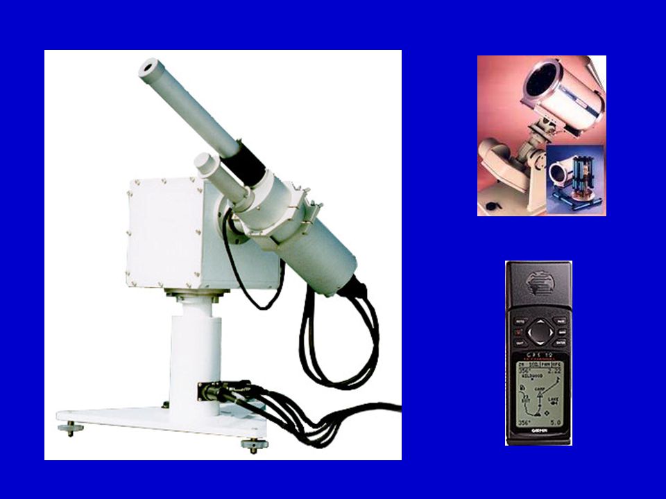
Sun tracker and shading ball arrangement Sun tracker fixed with pyrheliometer Sun tracker with shading ball arrangement & pyrheliometer Radiation sensor Shading balls

34
Part-3: POLLUTANT MEASUREMENTS In situ or direct sampling (e.g., high volume air samplers Remote measurements (sun photometer)
")
35
Direct Sampling High Volume Air Samplers

36
Aerosol Counter

37
Scanning Mobility Particle Sizer

38
0.1 1.010 Radius ( m)
")
40
Lambert-Beer Law dx I0I0 I I = I 0 exp(-k dx) F = F 0 exp(- m) m = slant / vertical V is proportional to I ln(V) = ln(V 0 ) - m This is an equation for a straight line with slope is “m” and y-intercept “ln(V 0 )”
 F = F 0 exp(- m) m = slant / vertical V is proportional to I ln(V) = ln(V 0 ) - m This is an equation for a straight line with slope is m and y-intercept ln(V 0 )")
41
Total = Molecules + Aerosols Molecules = ozone + Rayleigh

42
Part-4: CLOUDS AND WEATHER

43
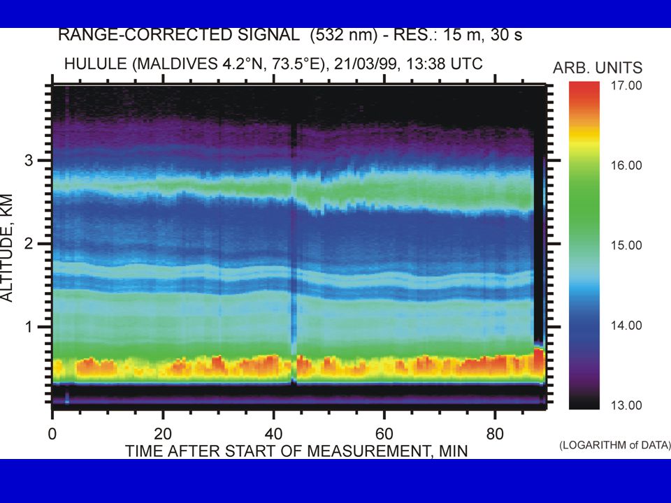
LIDAR in operation

44
Principle: Electromagnetic signal is recorded by a detector after it interacts with a target. By interpreting the changes caused in the return signal, the characteristics of the target can be inferred. S = F(T) T = F -1 (S)
 T = F -1 (S).")
45
LIDAR electronics

46
Simple Block Diagram of LIDAR

48
Aircraft Equipped with Optical Sensors for CLOUD and AEROSOL studies

49
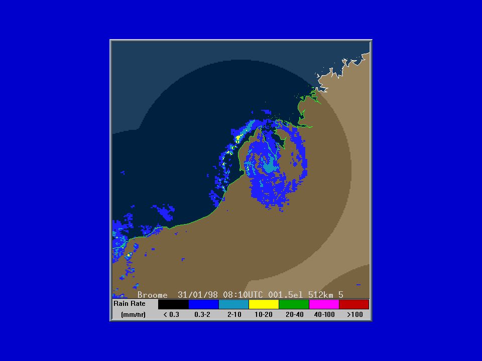
RADAR

50
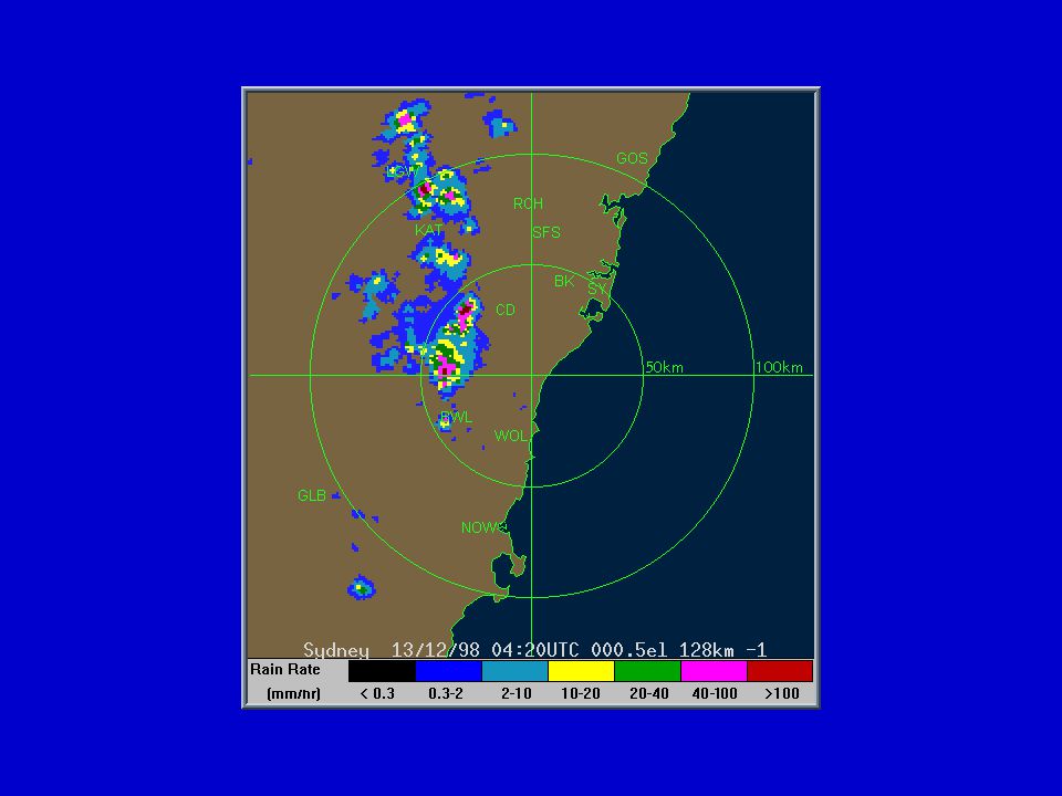
RADAR measures the range and location of targets. Targets can vary over a wide range. RADAR consists of three parts (a) Transmitter (2) Receiver (3) Electronics. Transmitter generates short pulses of energy in the microwave region of the EM spectrum and transmits as a narrow beam. If the pulses intercept an object with different refractive index than air, it causes some of the energy to be scattered. Part of the scattered energy will reach back the antenna. The Power of return signal (P) is given by RADAR equation which can be written in a simple form as, where Radar term contains the transmitted energy and Target term contains the returned energy. P = C [Radar term] [Target term]
 Transmitter (2) Receiver (3) Electronics. Transmitter generates short pulses of energy in the microwave region of the EM spectrum and transmits as a narrow beam. If the pulses intercept an object with different refractive index than air, it causes some of the energy to be scattered. Part of the scattered energy will reach back the antenna. The Power of return signal (P) is given by RADAR equation which can be written in a simple form as, where Radar term contains the transmitted energy and Target term contains the returned energy. P = C [Radar term] [Target term].")
51
Background Weather Target

55
Part-5: UPPER AIR OBSERVATIONS

56
1. Contamination Shield 2. Sensor Boom 3. Battery Connector 4. Battery Wire Attachment Points 5. Battery 6. Battery Container Cover

57
Altitude (m) RH (%) Temperature ( C)
 RH (%) Temperature ( C)")
58
Thank you

Similar presentations


 Atlas (1989)>")

 Accuracy: marked to 0.5 o C Cost: £10 Site: in the shade (e.g. a Stevenson Screen) Mercury.>")
 radiation: 1)>")


 Trent Weather Station (Lafleur)>")
 Results in conduction, convection and long-wave emission 2.Transmission (transmissivity=>")
>")
 Used for atmospheric profiling Measures P, T, RH, wind speed and direction Uncertainties arise from incorrect surface.>")


>")