Download presentation
Presentation is loading. Please wait.

1
Image-Based Lighting 15-463: Computational Photography Alexei Efros, CMU, Fall 2008 © Eirik Holmøyvik …with a lot of slides donated by Paul Debevec

2
Inserting Synthetic Objects Why does this look so bad? Wrong camera orientation Wrong lighting No shadows

3
Solutions Wrong Camera Orientation Estimate correct camera orientation and renender object –Requires camera calibration to do it right Lighting & Shadows Estimate (eyeball) all the light sources in the scene and simulate it in your virtual rendering But what happens if lighting is complex? Extended light sources, mutual illumination, etc.

4
Environment Maps Simple solution for shiny objects Models complex lighting as a panoramic image i.e. amount of radiance coming in from each direction A plenoptic function!!!

5
reflective surface viewer environment texture image v n r projector function converts reflection vector (x, y, z) to texture image (u, v) Environment Mapping Reflected ray: r=2(n·v)n-v Texture is transferred in the direction of the reflected ray from the environment map onto the object What is in the map?
 to texture image (u, v) Environment Mapping Reflected ray: r=2(n·v)n-v Texture is transferred in the direction of the reflected ray from the environment map onto the object What is in the map")
6
What approximations are made? The map should contain a view of the world with the point of interest on the object as the Center of Projection We can’t store a separate map for each point, so one map is used with the COP at the center of the object Introduces distortions in the reflection, but we usually don’t notice Distortions are minimized for a small object in a large room The object will not reflect itself!

7
Environment Maps The environment map may take various forms: Cubic mapping Spherical mapping other Describes the shape of the surface on which the map “resides” Determines how the map is generated and how it is indexed

8
Cubic Mapping The map resides on the surfaces of a cube around the object Typically, align the faces of the cube with the coordinate axes To generate the map: For each face of the cube, render the world from the center of the object with the cube face as the image plane –Rendering can be arbitrarily complex (it’s off-line) To use the map: Index the R ray into the correct cube face Compute texture coordinates
 To use the map: Index the R ray into the correct cube face Compute texture coordinates")
9
Cubic Map Example

10
Sphere Mapping Map lives on a sphere To generate the map: Render a spherical panorama from the designed center point To use the map: Use the orientation of the R ray to index directly into the sphere

11
Example

12
What about real scenes? From Flight of the Navigator

13
What about real scenes? from Terminator 2

14
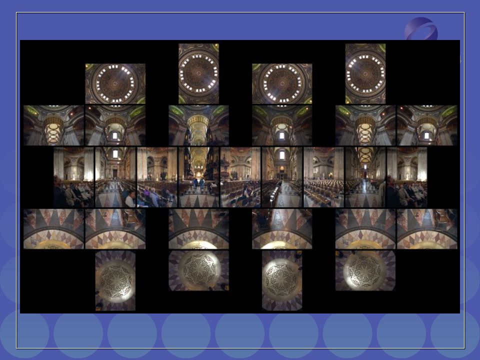
Real environment maps We can use photographs to capture environment maps The first use of panoramic mosaics How do we deal with light sources? Sun, lights, etc? They are much much brighter than the rest of the enviarnment User High Dynamic Range photography, of course! Several ways to acquire environment maps: Stitching mosaics Fisheye lens Mirrored Balls

15
Stitching HDR mosaics http://www.gregdowning.com/HDRI/stitched/

16
Scanning Panoramic Cameras Pros: very high res (10K x 7K+) Full sphere in one scan – no stitching Good dynamic range, some are HDR Issues: More expensive Scans take a while Companies: Panoscan, Sphereon Pros: very high res (10K x 7K+) Full sphere in one scan – no stitching Good dynamic range, some are HDR Issues: More expensive Scans take a while Companies: Panoscan, Sphereon
 Full sphere in one scan – no stitching Good dynamic range, some are HDR Issues: More expensive Scans take a while Companies: Panoscan, Sphereon Pros: very high res (10K x 7K+) Full sphere in one scan – no stitching Good dynamic range, some are HDR Issues: More expensive Scans take a while Companies: Panoscan, Sphereon")
17
See also www.kaidan.com

19
Fisheye Images

20
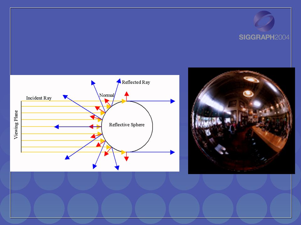
Mirrored Sphere

23
Sources of Mirrored Balls 2-inch chrome balls ~ $20 ea. McMaster-Carr Supply Company www.mcmaster.com 6-12 inch large gazing balls Baker’s Lawn Ornaments www.bakerslawnorn.com Hollow Spheres, 2in – 4in Dube Juggling Equipment www.dube.com FAQ on www.debevec.org/HDRShop/ 2-inch chrome balls ~ $20 ea. McMaster-Carr Supply Company www.mcmaster.com 6-12 inch large gazing balls Baker’s Lawn Ornaments www.bakerslawnorn.com Hollow Spheres, 2in – 4in Dube Juggling Equipment www.dube.com FAQ on www.debevec.org/HDRShop/

24
0.34 0.58 => 59% Reflective Calibrating Mirrored Sphere Reflectivity

25
Real-World HDR Lighting Environments Lighting Environments from the Light Probe Image Gallery: http://www.debevec.org/Probes/ Funston Beach Uffizi Gallery Eucalyptus Grove Grace Cathedral

26
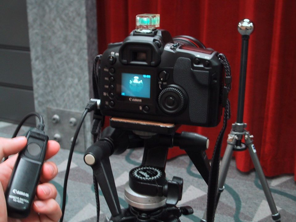
Acquiring the Light Probe

27
Assembling the Light Probe

28
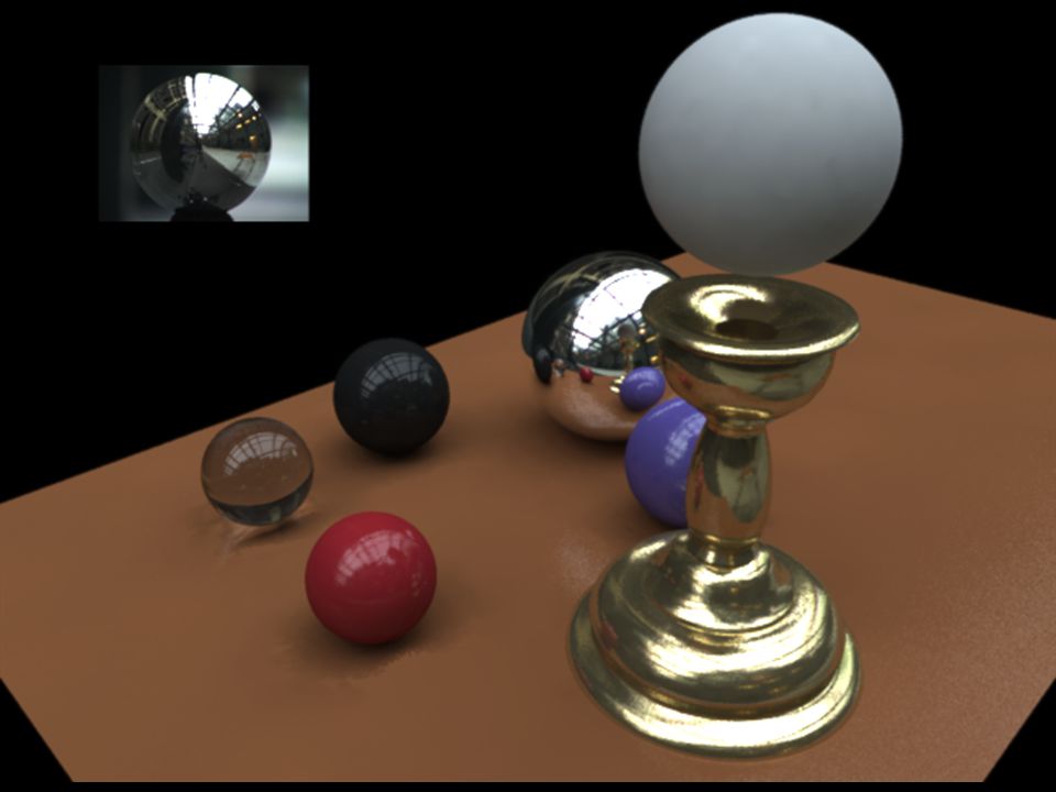
Not just shiny… We have captured a true radiance map We can treat it as an extended (e.g spherical) light source Can use Global Illumination to simulate light transport in the scene So, all objects (not just shiny) can be lighted What’s the limitation? We have captured a true radiance map We can treat it as an extended (e.g spherical) light source Can use Global Illumination to simulate light transport in the scene So, all objects (not just shiny) can be lighted What’s the limitation?
 light source Can use Global Illumination to simulate light transport in the scene So, all objects (not just shiny) can be lighted What’s the limitation .")
29
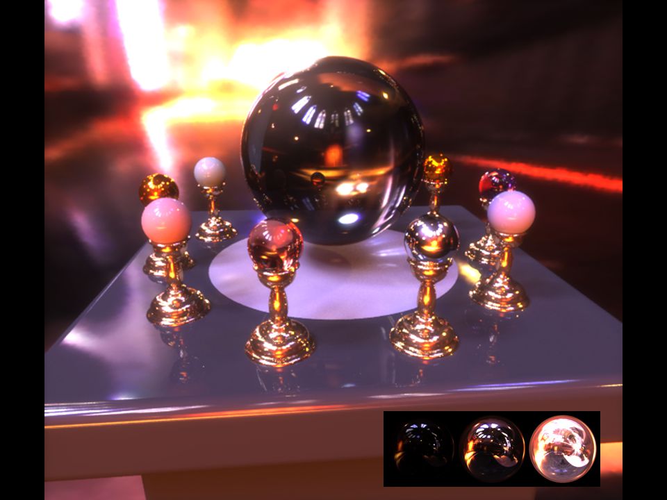
Illumination Results Rendered with Greg Larson’s RADIANCE synthetic imaging system Rendered with Greg Larson’s RADIANCE synthetic imaging system

30
Comparison: Radiance map versus single image

31
Putting it all together Synthetic Objects + Real light! Synthetic Objects + Real light!

32
CG Objects Illuminated by a Traditional CG Light Source

33
Illuminating Objects using Measurements of Real Light Object Light http://radsite.lbl.gov/radiance/ Environment assigned “glow” material property in Greg Ward’s RADIANCE system.

34
Paul Debevec. A Tutorial on Image-Based Lighting. IEEE Computer Graphics and Applications, Jan/Feb 2002.

35
Rendering with Natural Light SIGGRAPH 98 Electronic Theater

36
RNL Environment mapped onto interior of large cube

37
MOVIE!

38
It’s not that hard! http://www.nickbertke.com/

39
Illuminating a Small Scene

41
We can now illuminate synthetic objects with real light. How do we add synthetic objects to a real scene? We can now illuminate synthetic objects with real light. How do we add synthetic objects to a real scene?

42
Real Scene Example Goal: place synthetic objects on table

43
Light Probe / Calibration Grid

44
real scene Modeling the Scene light-based model

45
The Light-Based Room Model

46
real scene Modeling the Scene synthetic objects light-based model local scene

47
The Lighting Computation synthetic objects (known BRDF) synthetic objects (known BRDF) distant scene (light-based, unknown BRDF) local scene (estimated BRDF) local scene (estimated BRDF)
 synthetic objects (known BRDF) distant scene (light-based, unknown BRDF) local scene (estimated BRDF) local scene (estimated BRDF)")
48
Rendering into the Scene Background Plate

49
Rendering into the Scene Objects and Local Scene matched to Scene

50
Differential Rendering Local scene w/o objects, illuminated by model

51
Differential Rendering (2) Difference in local scene - - = =
 Difference in local scene - - = =")
52
Differential Rendering Final Result

54
I MAGE -B ASED L IGHTING IN F IAT L UX Paul Debevec, Tim Hawkins, Westley Sarokin, H. P. Duiker, Christine Cheng, Tal Garfinkel, Jenny Huang SIGGRAPH 99 Electronic Theater

56
HDR Image Series 2 sec 1/4 sec 1/30 sec 1/250 sec 1/2000 sec 1/8000 sec

57
Stp1 Panorama

58
Assembled Panorama

59
Light Probe Images

60
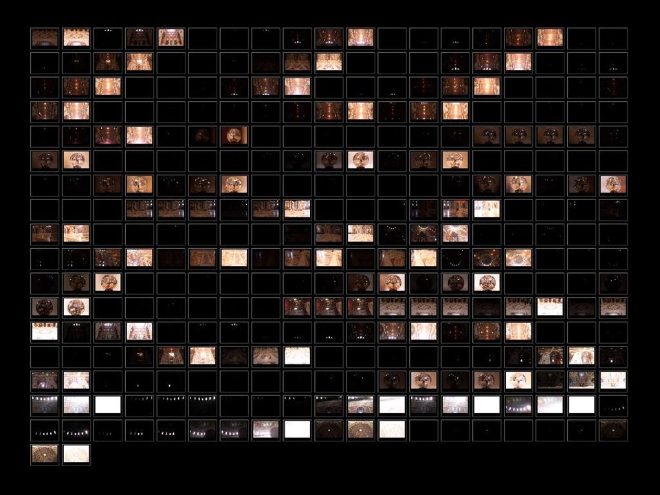
Capturing a Spatially-Varying Lighting Environment

61
The Movie

62
Simulating the Glare in the Human Eye Greg Spencer, Peter Shirley, Kurt Zimmerman, and Donald Greenberg. Physically-based glare effects for digital images. SIGGRAPH 95.

63
Scattering in the eye What’s the scattering model?

64
HDR Image

65
Gaussian Blur, LDR information Only

66
Gaussian Blur, Full HDR Information

67
Full HDR Disc Blur

68
Frame Postprocessing in Rendering with Natural Light

Similar presentations


![Real-Time High Quality Rendering COMS 6160 [Fall 2004], Lecture 4 Shadow and Environment Mapping](/16/5104377/big_thumb.jpg "Real-Time High Quality Rendering COMS 6160 [Fall 2004], Lecture 4 Shadow and Environment Mapping>")


