Download presentation
Presentation is loading. Please wait.

1
10/14/14 Image-based Lighting Computational Photography Derek Hoiem, University of Illinois Many slides from Debevec, some from Efros T2

2
Next two classes Today Mid-semester feedback Distribute light probes Start on ray tracing, environment maps, and relighting 3D objects (project 4 topics) Thursday More HDR, light probes, etc.
 Thursday More HDR, light probes, etc.")
3
Project 4

4
How to render an object inserted into an image? What’s wrong with the teapot?

5
How to render an object inserted into an image? Traditional graphics way Manually model BRDFs of all room surfaces Manually model radiance of lights Do ray tracing to relight object, shadows, etc.

6
http://smashinghub.com/8-of-the-most-epic- government-photoshop-fails-ever.htm http://petapixel.com/2013/10/13/another- north-korean-photoshop-fail/ Relighting is important!

7
How to render an object inserted into an image? Traditional graphics way Manually model BRDFs of all room surfaces Manually model radiance of lights Do ray tracing to relight object, shadows, etc.

8
How to render an object inserted into an image? Image-based lighting Capture incoming light with a “light probe” Model local scene Ray trace, but replace distant scene with info from light probe Debevec SIGGRAPH 1998

9
Key ideas for Image-based Lighting Environment maps: tell what light is entering at each angle within some shell +

10
Key ideas for Image-based Lighting Light probes: a way of capturing environment maps in real scenes

11
Key ideas for Image-based Lighting Capturing HDR images: needed so that light probes capture full range of radiance

12
Key ideas for Image-based Lighting Ray tracing: synthesize light paths between camera and light sources

13
Key ideas for Image-based Lighting Ray tracing: determining pixel intensity by shooting out rays from the camera

14
Key ideas for Image-based Lighting Relighting: environment map acts as light source, substituting for distant scene

15
Today Ray tracing Capturing environment maps

16
A photon’s life choices Absorption Diffusion Reflection Transparency Refraction Fluorescence Subsurface scattering Phosphorescence Interreflection λ light source ?

17
A photon’s life choices Absorption Diffusion Reflection Transparency Refraction Fluorescence Subsurface scattering Phosphorescence Interreflection λ light source

18
A photon’s life choices Absorption Diffuse Reflection Reflection Transparency Refraction Fluorescence Subsurface scattering Phosphorescence Interreflection λ light source

19
A photon’s life choices Absorption Diffusion Specular Reflection Transparency Refraction Fluorescence Subsurface scattering Phosphorescence Interreflection λ light source

20
A photon’s life choices Absorption Diffusion Reflection Transparency Refraction Fluorescence Subsurface scattering Phosphorescence Interreflection λ light source

21
A photon’s life choices Absorption Diffusion Reflection Transparency Refraction Fluorescence Subsurface scattering Phosphorescence Interreflection λ light source

22
A photon’s life choices Absorption Diffusion Reflection Transparency Refraction Fluorescence Subsurface scattering Phosphorescence Interreflection λ1λ1 light source λ2λ2

23
A photon’s life choices Absorption Diffusion Reflection Transparency Refraction Fluorescence Subsurface scattering Phosphorescence Interreflection λ light source

24
A photon’s life choices Absorption Diffusion Reflection Transparency Refraction Fluorescence Subsurface scattering Phosphorescence Interreflection t=1 light source t=n

25
A photon’s life choices Absorption Diffusion Reflection Transparency Refraction Fluorescence Subsurface scattering Phosphorescence Interreflection λ light source (Specular Interreflection)
")
26
A photon’s life choices Absorption Diffusion Reflection Transparency Fluorescence Interreflection Subsurface scattering Phosphoresence camera center image plane λ light source ?

27
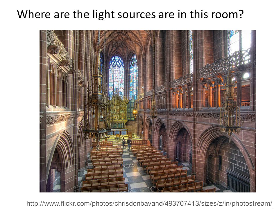
Where are the light sources are in this room? http://www.flickr.com/photos/chrisdonbavand/493707413/sizes/z/in/photostream/
28
Rendering Equation Incoming LightBRDFIncident angle Generated light Total reflected light Outgoing light

29
Rendering a scene with ray tracing http://en.wikipedia.org/wiki/File:Glasses_800_edit.png

30
Ray tracing: basics camera center image plane λ light source

31
Diffuse shading http://www.groovyvis.com/other/raytracing/basic.html

32
Reflections

33
Shadows

34
Ray casting Store colors of surfaces, cast out rays, see what colors each ray hits Wolfenstein 3D (1992)
")
35
Ray tracing: fast approximation Upon hitting a surface Cast reflection/refraction ray to determine reflected or refracted surface Cast shadow ray: go towards light and see if an object is in the way http://en.wikipedia.org/wiki/File:Ray_trace_diagram.svg

36
Ray tracing: interreflections Reflect light N times before heading to light source N=16 N=2 http://en.wikipedia.org/wiki/Ray_tracing_(graphics)#mediaviewer/File:Ray-traced_steel_balls.jpg

37
Ray tracing Conceptually simple but hard to do fast Full solution requires tracing millions of rays for many inter-reflections Design choices – Ray paths: Light to camera vs. camera to light? – How many samples per pixel (avoid aliasing)? – How to sample diffuse reflections? – How many inter-reflections to allow? – Deal with subsurface scattering, etc?
. – How to sample diffuse reflections. – How many inter-reflections to allow. – Deal with subsurface scattering, etc .")
38
Environment Maps The environment map may take various forms: – Cubic mapping – Spherical mapping – other Describes the shape of the surface on which the map “resides” Determines how the map is generated and how it is indexed

39
Cubic Map Example

40
Cubic Mapping The map resides on the surfaces of a cube around the object – Typically, align the faces of the cube with the coordinate axes To generate the map: – For each face of the cube, render the world from the center of the object with the cube face as the image plane Rendering can be arbitrarily complex (it’s off-line) To use the map: – Index the R ray into the correct cube face – Compute texture coordinates
 To use the map: – Index the R ray into the correct cube face – Compute texture coordinates")
41
Spherical Map Example

42
Sphere mapping Map lives on a sphere To generate the map: – Render a spherical panorama from the designed center point Rendering with environment map: – Use the orientation of the R ray to index directly into the sphere

43
What approximations are made? The map should contain a view of the world with the point of interest on the object as the Center of Projection – We can’t store a separate map for each point, so one map is used with the COP at the center of the object – Introduces distortions in the reflection, but we usually don’t notice – Distortions are minimized for a small object in a large room The object will not reflect itself!

44
Rendering with environment maps and local models camera center image plane

45
Storing spherical environment maps

46
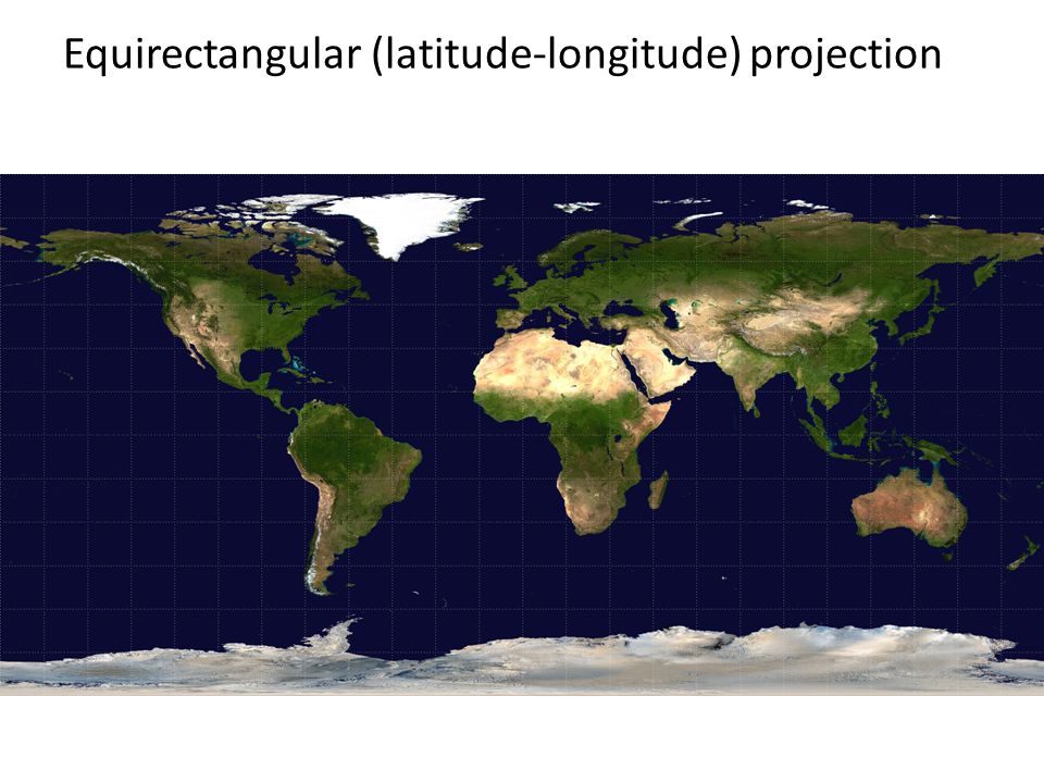
Equirectangular (latitude-longitude) projection
 projection")
48
What about real scenes? From Flight of the Navigator

49
What about real scenes? from Terminator 2

50
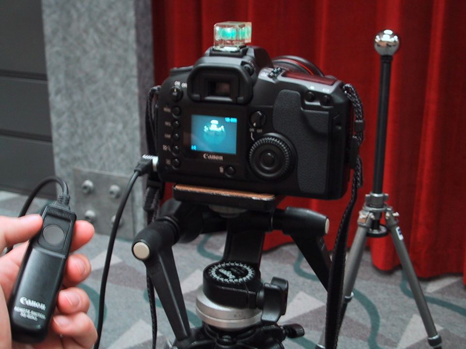
Real environment maps We can use photographs to capture environment maps – The first use of panoramic mosaics – Fisheye lens – Mirrored balls (light probes)
")
51
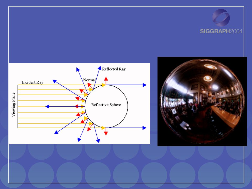
Mirrored Sphere

54
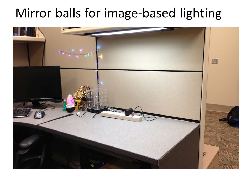
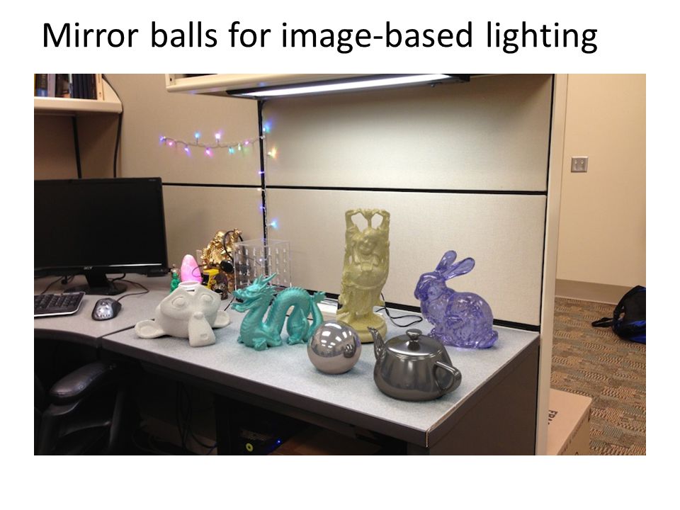
Mirror balls for image-based lighting

57
Sources of Mirrored Balls 2-inch chrome balls ~ $20 ea. McMaster-Carr Supply Company www.mcmaster.com 6-12 inch large gazing balls Baker’s Lawn Ornaments www.bakerslawnorn.com Hollow Spheres, 2in – 4in Dube Juggling Equipment www.dube.com FAQ on www.debevec.org/HDRShop/ 2-inch chrome balls ~ $20 ea. McMaster-Carr Supply Company www.mcmaster.com 6-12 inch large gazing balls Baker’s Lawn Ornaments www.bakerslawnorn.com Hollow Spheres, 2in – 4in Dube Juggling Equipment www.dube.com FAQ on www.debevec.org/HDRShop/

58
0.34 0.58 => 59% Reflective Calibrating Mirrored Sphere Reflectivity

59
Spherical map domain transformations Many rendering programs only accept one format (mirror ball, equirectangular, cube map, etc) – E.g. Blender only accepts equirectangular maps How to convert mirror ball to equirectangular?

60
Mirror ball -> equirectangular

61
Spherical coordinates – Convert the light directions incident to the ball into spherical coordinates (phi, theta) – Map from mirror ball phi, theta to equirectangular phi, theta for i=1:d F = TriScatteredInterp(phi_ball, theta_ball, mirrorball(:,:,i)); latlon(:,:,i) = F(phi_latlon, theta_latlon); end
 – Map from mirror ball phi, theta to equirectangular phi, theta for i=1:d F = TriScatteredInterp(phi_ball, theta_ball, mirrorball(:,:,i)); latlon(:,:,i) = F(phi_latlon, theta_latlon); end")
62
Mirror ball -> equirectangular Mirror ball Equirectangular NormalsReflection vectors Phi/theta of reflection vecs Phi/theta equirectangular domain

63
One small snag How do we deal with light sources? Sun, lights, etc? – They are much, much brighter than the rest of the environment 1 46 1907 15116 18.....

64
Problem: Dynamic Range

65
1500 1 1 25,000 400,000 2,000,000,000 The real world is high dynamic range.

66
Long Exposure 10 -6 10 6 10 -6 10 6 Real world Picture 0 to 255 High dynamic range

67
Short Exposure 10 -6 10 6 10 -6 10 6 Real world Picture High dynamic range 0 to 255

68
Camera Calibration Geometric –How pixel coordinates relate to directions in the world Photometric –How pixel values relate to radiance amounts in the world Geometric –How pixel coordinates relate to directions in the world Photometric –How pixel values relate to radiance amounts in the world

69
The Image Acquisition Pipeline scene radiance (W/sr/m ) scene radiance (W/sr/m ) sensor irradiance sensor irradiance sensor exposure sensor exposure latent image latent image Lens Shutter Film Electronic Camera 2 2 tttt film density film density analog voltages analog voltages digital values digital values pixel values pixel values Development CCD ADC Remapping
 scene radiance (W/sr/m ) sensor irradiance sensor irradiance sensor exposure sensor exposure latent image latent image Lens Shutter Film Electronic Camera 2 2 tttt film density film density analog voltages analog voltages digital values digital values pixel values pixel values Development CCD ADC Remapping")
70
log Exposure = log (Radiance * t) Imaging system response function Pixelvalue 0 255 (CCD photon count)
 Imaging system response function Pixelvalue (CCD photon count)")
71
Varying Exposure

72
Camera is not a photometer! Limited dynamic range Perhaps use multiple exposures? Unknown, nonlinear response Not possible to convert pixel values to radiance Solution: –Recover response curve from multiple exposures, then reconstruct the radiance map Limited dynamic range Perhaps use multiple exposures? Unknown, nonlinear response Not possible to convert pixel values to radiance Solution: –Recover response curve from multiple exposures, then reconstruct the radiance map

73
Next class How to capture HDR image using “bracketing” How to relight an object from an environment map

Similar presentations


 Using two known backgrounds.>")


