Download presentation
Presentation is loading. Please wait.

2
Colorado Space Grant Consortium Gateway To Space ASEN / ASTR 2500 Class #06 Gateway To Space ASEN / ASTR 2500 Class #06 T-58

3
Today:

4
-Announcements -One Minute Reports -HOBOs, Cameras, Foamcore, Insulation, Multimeters -Next Tuesday is catch up and in class team time Today:

5
-Website now has presentations -Give man a fish… -Innovate ideas don’t have solutions - Breadcrumbs (HW) Announcements:
 Announcements:")
6
Colorado Space Grant Consortium Foamcore ASEN / ASTR 2500 Foamcore ASEN / ASTR 2500

7
6 - BalloonSats are commonly made of foam core - Foam core is a simple, low cost composite panel - You will use hot glue and Xacto knives to create your box - There is a OK way of building with foam core - Cut individual pieces and glue them together - This way works but is not the best and requires more “belts and suspenders” Hands-on: Construction and Integration

8
7 BalloonSat Construction: - There is a BETTER way of building with foam core - Requires algebra and geometry - See paper in back of your course book -

9
8 BalloonSat Construction: - When cutting foam core, remember you are cutting through three layers - Best to cut each layer individually - Go slow, use metal edge ruler - Be mindful

10
9 - Step 1: Layout box design on foam core sheet In the interest of time, each team will be given a pre-traced foam board (black with labels) BalloonSat Construction:
 BalloonSat Construction:")
11
10

12
11 BalloonSat Construction: - Step 2: Cut it out

13
12 BalloonSat Construction: - Step 2: Cut it out

14
13 - Draw center lines between inner and outer lines - All edge cuts are at 45 degree angles to the centerline - Cut inside edges first and only through top paper and foam not bottom paper (hinge) - Cut outside edges last but all the way through - Go Slow and don’t cut the tables - Please dispose of Xacto blades properly Hands-on: Construction and Integration
 - Cut outside edges last but all the way through - Go Slow and don’t cut the tables - Please dispose of Xacto blades properly Hands-on: Construction and Integration")
15
14 Hands-on: Construction and Integration

16
15 - Cut holes for switch and camera lens - Cut hole through center for balloon attachment tube Hands-on: Construction and Integration

17
16 BalloonSat Construction: - Step 3: Practice integration and make modifications Hold box together and figure out how much insulation you want to use. Will affect how your components sit in box

18
17 BalloonSat Construction: - Step 4: Glue it together and strengthen corners - Your template was designed using the “Better Method” - After gluing, cover you seams with aluminum tape - Please don’t go overboard, weight is still an issue

19
18 BalloonSat Construction: - Step 4: Glue it together and strengthen corners

20
19 BalloonSat Construction: Things to remember: You only have one - Switches

21
20 - Install switches to box and glue switches in place from back side before making electrical connections - Keep switches on both sides and label ON/OFF positions - Make sure to re-connect the switch Hands-on: Construction and Integration

22
21 - Balloon attachment tube hole should run through center of box on non- opening side - Make hole diameter as close to tube diameter as possible - Secure with paper clip - Make sure paper clip does not interfere with inner diameter Hands-on: Construction and Integration

23
22 BalloonSat Construction: Resources available for checkout: - Soldering stations - ½” and ¼” foam insulation - Foamcore - Velcro - Tape - Peace and love

24
Colorado Space Grant Consortium Multimeters ASEN / ASTR 2500 Multimeters ASEN / ASTR 2500

25
Today:

26
25 - Voltmeter is very useful

27
26 Voltmeter 101: - This is the set up typically used

28
27 Voltmeter 101: - Use this setting to check resistor values

29
28 Voltmeter 101: - Use this setting to check DC voltage

30
29 Voltmeter 101: - Use this setting to check continuity

31
Colorado Space Grant Consortium HOBOs ASEN / ASTR 2500 HOBOs ASEN / ASTR 2500

32
Today:

33
HOBO Data Logger RH Sensor Temp Sensor External Channels Serial Port LED Indicator

34
HOBO Data Logger RH Sensor Temp Sensor External Channels Serial Port LED Indicator Battery (back side)
")
35
34 - Data Loggers our like our “Black Boxes” HOBO Data Logger Burst (30 km) Tropopause Coldest Launch Landing
 Tropopause Coldest Launch Landing")
36
Step 4: Connect Temperature cable (TMC1-HA) to channel 4 on HOBO Computer Hands-on: Temperature Experiment
 to channel 4 on HOBO Computer Hands-on: Temperature Experiment")
37
Step 7: Start HOBO Box Car 3.7 software Hands-on: Temperature Experiment

38
Step 8: Launch HOBO computer Hands-on: Temperature Experiment

39
Step 9: Check Battery & select “Enable/Disable Channels” Hands-on: Temperature Experiment

40
Step 10: Select Channel 4 Hands-on: Temperature Experiment

41
Step 11: Select correct temperature cable Hands-on: Temperature Experiment

42
Step 14: Select Data sampling or interval Hands-on: Temperature Experiment

43
Step 15: Confirm Settings and select Start Hands-on: Temperature Experiment

44
Step 16: Unplug PC cable from HOBO Hands-on: Temperature Experiment

45
Take and Retrieve Data Hands-on: Temperature & Solar Experiments

46
Step 17: Give your HOBO sensor some data Hands-on: Temperature Experiment

47
Step 18: Connect PC Cable to HOBO Step 19: Select Readout Hands-on: Temperature Experiment

48
Step 20: Verify data download Hands-on: Temperature Experiment

49
Step 21: Disconnect PC cable from HOBO Hands-on: Temperature Experiment

50
Step 22: Name Data Hands-on: Temperature Experiment

51
Step 23: View Data Hands-on: Temperature Experiment

52
Step 24: Change data channel Hands-on: Temperature Experiment

53
Step 25: View Data from Channel 4 Hands-on: Temperature Experiment

54
Delay Start Feature Hands-on: Temperature & Solar Experiments

55
To save time tomorrow and launch day… - IMPORTANT: Make sure laptop time and date is correct for Colorado Mountain Daylight Time Hands-on: Temperature Experiment

56
- Repeat Steps 1 through 13 - Step 26: Set sampling rate to 15 Sec - This will give you over 8 hours of data Hands-on: Temperature Experiment

57
- Step 27: Select Delay Start - Step 28: Set the date and time to 07- 15-06 at 7:00 AM - Step 29: Select Start Hands-on: Temperature Experiment

58
Step 30: Unplug PC cable from HOBO Hands-on: Temperature Experiment

59
Step 31: Store HOBO and cables in box This concludes the set and initialization for the Temperature and Solar Experiments Hands-on: Temperature Experiment

60
Colorado Space Grant Consortium Heaters ASEN / ASTR 2500 Heaters ASEN / ASTR 2500

61
Today:

62
61 Environments at 30 km: - You need to do something to keep your systems warm - Colorado history has shown payloads (batteries) begin to fail below -5°C - Hand warmers don’t work well without air (O 2 ) - You will use an active heater
 begin to fail below -5°C - Hand warmers don’t work well without air (O 2 ) - You will use an active heater")
63
62 BalloonSats can do real science at 100,000 feet Discoveries can be made Atmospheric studies can be done Engineering challenges are extreme Enough unknowns to catch the mind of students Environments at 30 km:

64
63 Hands-on: Heater Circuit - Dry ice test results have been excellent

65
64 Hands-on: Heater Circuit Kit includes: 3 9 Volt batteries (for flight only) 1 Perf Board 3Ceramic Resistors (4 Ω @ 5W) 39 V connectors 1 White wire 1 Blue wire 1 Red wire 1 Black wire 1 Switch 1 Female connector with red and black wire
 1 Perf Board 3Ceramic Resistors (4 5W) 39 V connectors 1 White wire 1 Blue wire 1 Red wire 1 Black wire 1 Switch 1 Female connector with red and black wire")
66
65 Hands-on: Heater Circuit Set out kit

67
66 Hands-on: Heater Circuit Layout Resistors on Perf Board

68
67 Hands-on: Heater Circuit Layout Resistors on Perf Board Back Front

69
68 Hands-on: Heater Circuit Fold over the leads from two of the blocks and solder them together

70
69 Hands-on: Heater Circuit Snip the leads that you just soldered together

71
70 Hands-on: Heater Circuit Fold over the opposite two leads and solder so that all of the blocks are connected in parallel then clip the ends of the leads

72
71 Hands-on: Heater Circuit Solder resistors in series using leads of resistors 4Ω4Ω4Ω4Ω4Ω4Ω

73
72 Hands-on: Heater Circuit Twist all the Red wires from the 9V connector together and solder them to the single BLUE wire in your kit

74
73 Hands-on: Heater Circuit Twist all the Black wires from the 9V connector together and solder them to the single black wire from the female connector

75
74 Hands-on: Heater Circuit Check continuity for all “-” and “+” terminals to each other

76
75 Hands-on: Heater Circuit Check continuity for all “+” terminals of the battery with the end of the single BLUE wire Check continuity for all “-” terminals of the battery with the end of the single BLACK wire

77
76 Hands-on: Heater Circuit Check continuity for all “-” terminals of the battery with the BLACK wire on the connector

78
77 Hands-on: Heater Circuit Put electrical tape on solder joints

79
78 Hands-on: Heater Circuit Solder the single BLUE wire from 9V connector to one end of the resistor string and the RED wire from the female connector to the other end of the resistor string 4Ω4Ω4Ω4Ω4Ω4Ω

80
79 Hands-on: Heater Circuit Connect the Switch (Black to Black, Red to Red)
")
81
80 Hands-on: Heater Circuit Final Product

82
81 Hands-on: Heater Circuit Attach 3 flight batteries and turn switch on. Your heater will get extremely hot with in 1 to 2 minutes. If it takes longer, please let me know.

83
82 Hands-on: Heater Circuit Turn switch off, disconnect the switch from the heater, leave batteries connected

84
Colorado Space Grant Consortium Cameras ASEN / ASTR 2500 Cameras ASEN / ASTR 2500

85
Today:

86
-The following instructions will walk you through the steps needed to change the firmware on this camera to take picture every 20 seconds Canon A570 IS Mods:

87
-The CHDK code was originally written by Rick von Glahn from Edge of Space Sciences (EOSS) -These steps are performed with the camera modified to turn on and off with a external switch -The steps to modify the hardware of the camera are contained in a different presentation -2GB can hold ~ 566 pictures Canon A570 IS Mods:
 -These steps are performed with the camera modified to turn on and off with a external switch -The steps to modify the hardware of the camera are contained in a different presentation -2GB can hold ~ 566 pictures Canon A570 IS Mods:")
88
-This mod uses CHDK to add autonomy to a digital camera without the use of a timing circuit or further modifications to the camera -CHDK is firmware enhancement -It only works with Canon digital cameras -Please see the following website for much more information http://chdk.wikia.com/wiki/CHDK Canon A570 IS Mods:

89
http://chdk.wikia.com/wiki/CHDK Canon A570 IS Mods:

90
-Take your camera out of the box Canon A570 IS Mods:

91
-Insert the batteries Canon A570 IS Mods:

92
- Turn on camera by touching two wires together Canon A570 IS Mods:

93
- Set the date and time - Power off the camera by touching the two wires together again Canon A570 IS Mods:

94
-Insert SD card and close battery cover (not all SD cards support this mod) Canon A570 IS Mods: 1. 2. 3. 4. 5.
95
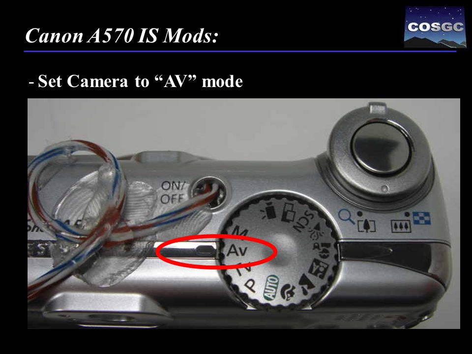
-Set Camera to “AV” mode Canon A570 IS Mods:

96
-Turn on camera by touching two wires together Canon A570 IS Mods:

97
-Press the “MENU” button and format the card – Use the “Low Level Format” setting Canon A570 IS Mods: 1. 2.

98
Canon A570 IS Mods: -Press the “MENU” button and format the card – Use the “Low Level Format” setting 3. 4.

99
Canon A570 IS Mods: -Press the “MENU” button and format the card – Use the “Low Level Format” setting 5. 6.

100
-Power off camera and remove the SD Card Canon A570 IS Mods: 1. 2.

101
-Connect the SD card to your computer Canon A570 IS Mods: 1. 2.

102
-The files we are going to copy to the SD card contain a script (macro) that will take pictures about every 20 seconds after an initial boot up. Canon A570 IS Mods:

103
-Open the “cu_gateway_fall_2009.bas” file Canon A570 IS Mods: 1.

104
-Open the “cu_gateway_fall_2009.bas” file Canon A570 IS Mods: 2. 3.

105
-Open the “cu_gateway_fall_2009.bas” file Canon A570 IS Mods: 4. 5.

106
-Open the “cu_gateway_fall_2009.bas” file Canon A570 IS Mods: 6.

107
-Save the “cu_gateway_fall_2009.bas” file Canon A570 IS Mods:

108
-Copy the CHDK folder structure and files to the SD card Canon A570 IS Mods:

109
-Switch the play/record button on the camera to “play” Canon A570 IS Mods:

110
-Insert SD card and power the camera on. Canon A570 IS Mods: 1. 2. 3.

111
-Press the “MENU” button and press the left on the circle button until the “play” symbol is highlighted Canon A570 IS Mods: 1. 2. 3.
112
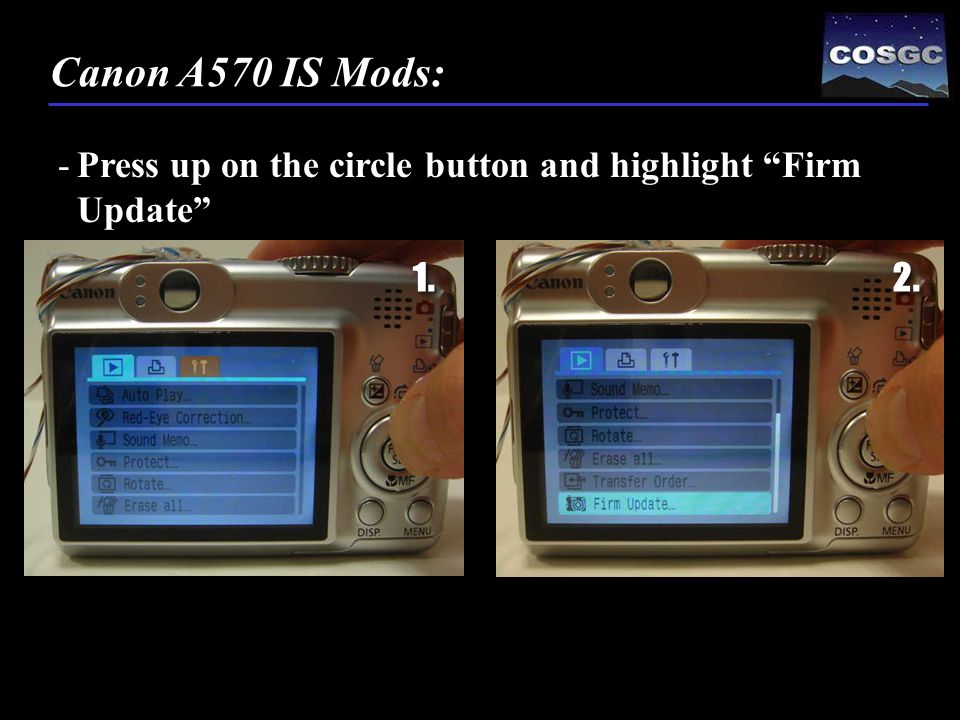
-Press up on the circle button and highlight “Firm Update” Canon A570 IS Mods: 1. 2.

113
-Select “OK” and press “SET” Canon A570 IS Mods: 1. 2.

114
-Camera should now be running the CHDK firmware. -May be default script or Gateway script. Canon A570 IS Mods:

115
-Press the shutter button to stop the script but leave the camera on Canon A570 IS Mods:

116
-Switch the play/record button on the camera to “record” Canon A570 IS Mods:

117
-You should see “Default Script” and “ ” in the bottom of the screen Canon A570 IS Mods:

118
-With “ ” showing, press the “MENU” button Canon A570 IS Mods:

119
- “ ” will be replaced by “ ” Canon A570 IS Mods:

120
- Use the control pad to move the cursor down to "Debug parameters" and click "SET" to select this option. Canon A570 IS Mods:

121
-Move the cursor down to "Make card bootable...“ -Press "SET" to select this option then select back and press “SET” again Canon A570 IS Mods:

122
-Nothing should happen. This is OK -Power off camera. Canon A570 IS Mods:

123
-Remove the SD card and slide switch to “LOCKED” Canon A570 IS Mods: Even though the card is in the “LOCKED” position it will be able to be written to via the CHDK firmware.

124
-Power on the camera - If the script that runs is the Gateway 2009 script than you can skip to end of these steps Canon A570 IS Mods: -Insert locked SD card and make sure the camera is in “RECORD” mode

125
-Power on the camera - “Default Script” and the “ ” should be visible -Press the shutter button to stop script Canon A570 IS Mods: -Insert locked SD card and make sure the camera is in “RECORD” mode

126
-With “ ” showing, click on the menu to get to the “ ” screen. Canon A570 IS Mods:

127
-Use the control pad to move the cursor down to "Scripting parameters" and push "SET" Canon A570 IS Mods:

128
-On the “Script” menu select "Load script from file..." Canon A570 IS Mods:

129
-On the "Select script file" screen, move the cursor to highlight "cu_gateway_fall_2009.bas>" and press "SET" Canon A570 IS Mods:

130
-When you return to the “Script” menu ensure that "Script Autostart" is checked (a dot in its selection field). Canon A570 IS Mods: -Also make sure the “Current script” is correct

131
-Now click "MENU” to save these changes to the configuration file Canon A570 IS Mods:

132
-Turn off camera -The next time the camera is turned on, it will run the script -It will go through a series of camera setting changes which will take about 60 seconds -Then the camera will begin to take pictures every 20 seconds until the card is full Canon A570 IS Mods:

133
-Sometimes the script doesn't execute properly the first time it runs. -If this happens, let it run it's course for around a minute or so then turn the camera off then on again and it should work fine -It should continue to work just fine on every subsequent power up Canon A570 IS Mods:

134
-Turn on the camera Canon A570 IS Mods:

135
-You can turn the camera off anytime. -If you wish to stop the script during execution just press the shutter release button and that will interrupt the execution of the script -Next press the printer button to gain control of the camera without having to remove the card -This is handy if you want to review photos, or do something else without the script running. Canon A570 IS Mods:

136
-After the pushing the shutter, you must push the print button to have normal camera operation Canon A570 IS Mods:

137
-Any setting you might make to the camera will be restored to factory default settings next time the script runs as that is the first action the script takes - Once you interrupt a script it must be re-run from the beginning you can not PAUSE a script and RESUME it - Pictures on card should be in the JPEG format not *.RAW format - To delete pictures, you must remove card and lock Canon A570 IS Mods:

138
-You can modify your code without reloading the firmware -For example lets change the “sleep” value to 5000 Canon A570 IS Mods:

139
-Power off camera -Remove SD Card -Unlock SD Card -Open CHDK/Scripts/cu_gateway_fall_2009.bas -Scroll down to end of code and change sleep = 5000 -Save Canon A570 IS Mods:

140
- Remove SD card and lock -Insert SD card into the camera and power on -Pictures should be taken every 8 to 10 seconds now -I would suggest a 20 second (sleep = 16000) for 135 minute flight time Canon A570 IS Mods:
 for 135 minute flight time Canon A570 IS Mods:")
141
-You can also “rem” out pieces of the set up or other functions but test first -Camera is working, it shall also be working at the end of the semester -Take good care of this camera -Thank you. Canon A570 IS Mods:

Similar presentations


 1 Perf Board 3Ceramic Resistors (4 5W) 39 V connectors 1 White wire 1.>")
>")


