Download presentation
Presentation is loading. Please wait.

2
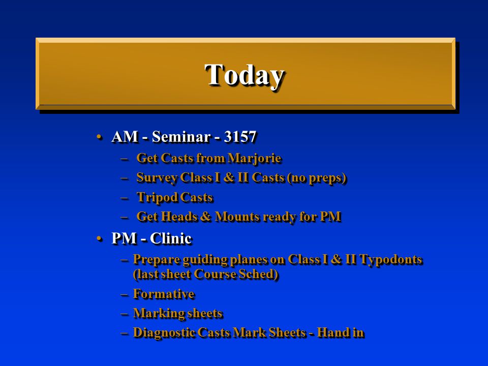
TodayToday AM - Seminar - 3157AM - Seminar - 3157 – Get Casts from Marjorie – Survey Class I & II Casts (no preps) – Tripod Casts – Get Heads & Mounts ready for PM PM - ClinicPM - Clinic –Prepare guiding planes on Class I & II Typodonts (last sheet Course Sched) –Formative –Marking sheets –Diagnostic Casts Mark Sheets - Hand in AM - Seminar - 3157AM - Seminar - 3157 – Get Casts from Marjorie – Survey Class I & II Casts (no preps) – Tripod Casts – Get Heads & Mounts ready for PM PM - ClinicPM - Clinic –Prepare guiding planes on Class I & II Typodonts (last sheet Course Sched) –Formative –Marking sheets –Diagnostic Casts Mark Sheets - Hand in
 – Tripod Casts – Get Heads & Mounts ready for PM PM - ClinicPM - Clinic –Prepare guiding planes on Class I & II Typodonts (last sheet Course Sched) –Formative –Marking sheets –Diagnostic Casts Mark Sheets - Hand in AM - Seminar AM - Seminar – Get Casts from Marjorie – Survey Class I & II Casts (no preps) – Tripod Casts – Get Heads & Mounts ready for PM PM - ClinicPM - Clinic –Prepare guiding planes on Class I & II Typodonts (last sheet Course Sched) –Formative –Marking sheets –Diagnostic Casts Mark Sheets - Hand in")
3
Surveying, Path of Insertion, Guiding Planes

4
DefinitionsDefinitions Height of contourHeight of contour Undercut = InfrabulgeUndercut = Infrabulge SuprabulgeSuprabulge

5
DefinitionsDefinitions Height of contourHeight of contour Undercut = InfrabulgeUndercut = Infrabulge SuprabulgeSuprabulge

6
Rule: Retentive tip should usually be designed to be placed in the gingival 1/3

7
Path of Insertion Path that the prosthesis isPath that the prosthesis is –Placed/removed –Usually a single path Path that the prosthesis isPath that the prosthesis is –Placed/removed –Usually a single path

8
Advantages of a Single Path of Insertion Equalizes retentionEqualizes retention

9
Advantages of a Single Path of Insertion Bracing and Cross-arch StabilizationBracing and Cross-arch Stabilization

10
Advantages of a Single Path of Insertion Minimizes torque on abutmentsMinimizes torque on abutments

11
Advantages of a Single Path of Insertion Allows removal without encountering interferencesAllows removal without encountering interferences

12
Advantages of a Single Path of Insertion Directs forces along long axes of teethDirects forces along long axes of teeth

13
Advantages of a Single Path of Insertion Provides frictional retentionProvides frictional retention

14
Selecting a Single Path of Insertion Use a dental surveyor toUse a dental surveyor to –Select path –Prepare guiding planes Use a dental surveyor toUse a dental surveyor to –Select path –Prepare guiding planes

15
Guiding Plane Preparation Where rigid components contact abutmentsWhere rigid components contact abutments Proximal PlatesProximal Plates Bracing ArmsBracing Arms Rigid portions of Retentive ArmsRigid portions of Retentive Arms

16
Other Uses of a Surveyor Blocking out undesirable undercutsBlocking out undesirable undercuts –Ensures the framework is not cast in an undercut Blocking out undesirable undercutsBlocking out undesirable undercuts –Ensures the framework is not cast in an undercut

17
Parts of a Surveyor Surveying TableSurveying Table

18
Parts of a Surveyor Surveying ArmSurveying Arm

19
Parts of a Surveyor Surveying ToolsSurveying Tools –Analyzing Rod Surveying ToolsSurveying Tools –Analyzing Rod

20
Parts of a Surveyor Surveying ToolsSurveying Tools –Carbon Markers Surveying ToolsSurveying Tools –Carbon Markers

21
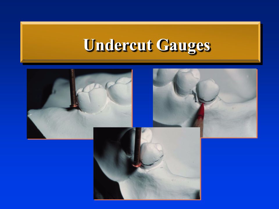
Parts of a Surveyor Surveying ToolsSurveying Tools –Undercut Gauges Surveying ToolsSurveying Tools –Undercut Gauges. 01”. 03”. 02”
22
Undercut Gauges

23
Parts of a Surveyor Surveying ToolsSurveying Tools –Wax Trimmer Surveying ToolsSurveying Tools –Wax Trimmer

24
Selecting a Path of Insertion Orient cast relatively horizontalOrient cast relatively horizontal –Final tilt rarely more than 10° from horizontal Orient cast relatively horizontalOrient cast relatively horizontal –Final tilt rarely more than 10° from horizontal

25
Selecting a Path of Insertion Place analyzing rod against abutmentsPlace analyzing rod against abutments –Contact point is Height of Contour -Below is infrabulge -Above is suprabulge Place analyzing rod against abutmentsPlace analyzing rod against abutments –Contact point is Height of Contour -Below is infrabulge -Above is suprabulge

26
Selecting a Path of Insertion Tilt cast to obtain maximum parallelismTilt cast to obtain maximum parallelism –Heights of contour are at relatively same position occluso-gingivally –Equal amounts of undercut Tilt cast to obtain maximum parallelismTilt cast to obtain maximum parallelism –Heights of contour are at relatively same position occluso-gingivally –Equal amounts of undercut

27
Altering Path of Insertion Proximal surfaces similar undercutsProximal surfaces similar undercuts Retentive areas similar undercutsRetentive areas similar undercuts Proximal surfaces similar undercutsProximal surfaces similar undercuts Retentive areas similar undercutsRetentive areas similar undercuts

28
Selecting a Path of Insertion Modify tilt if necessaryModify tilt if necessary –Soft tissue interferences Modify tilt if necessaryModify tilt if necessary –Soft tissue interferences

29
Selecting a Path of Insertion Modify tilt if necessaryModify tilt if necessary –Esthetics Modify tilt if necessaryModify tilt if necessary –Esthetics

30
Once Path Selected Instructor:Instructor: –Approves path –Demo: - Mark heights of contour with carbon marker -Tripod Instructor:Instructor: –Approves path –Demo: - Mark heights of contour with carbon marker -Tripod

31
Selecting a Path of Insertion Lock cast position & tripodLock cast position & tripod

32
TripodingTripoding

33
Optimal Path of Insertion Retentive undercuts equalizedRetentive undercuts equalized –Retentive arm has a different path of escapement than guiding plane, so it must flex during removal Retentive undercuts equalizedRetentive undercuts equalized –Retentive arm has a different path of escapement than guiding plane, so it must flex during removal

34
Optimal Path of Insertion Retentive undercuts equalizedRetentive undercuts equalized –Ideally, retentive arms should oppose each other on opposite sides of the arch Retentive undercuts equalizedRetentive undercuts equalized –Ideally, retentive arms should oppose each other on opposite sides of the arch

35
Optimal Path of Insertion Minimize severe tooth & soft tissue interferencesMinimize severe tooth & soft tissue interferences

36
Optimal Path of Insertion EstheticsEsthetics –Minimize display of clasps, metal components EstheticsEsthetics –Minimize display of clasps, metal components

37
Optimal Path of Insertion Prepare Guiding PlanesPrepare Guiding Planes –Flat surfaces parallel to path of insertion –Control & limit movement of RPD –Initial contacts for RPD Prepare Guiding PlanesPrepare Guiding Planes –Flat surfaces parallel to path of insertion –Control & limit movement of RPD –Initial contacts for RPD

38
Guiding Planes StabilizationStabilization

39
Effectiveness of Guideplanes Most effective when:Most effective when: –Parallel to each other –More than one common axial surface Most effective when:Most effective when: –Parallel to each other –More than one common axial surface

40
Effectiveness of Guideplanes Most effective when:Most effective when: –Directly opposing each other Most effective when:Most effective when: –Directly opposing each other

41
Effectiveness of Guideplanes Most effective when:Most effective when: –Prepared on several teeth –Cover a large surface area Most effective when:Most effective when: –Prepared on several teeth –Cover a large surface area

42
Assessing Guiding Planes Proximal View Facial View Carbon Markings

43
Preparing Guiding Planes Select path of insertionSelect path of insertion Design Partial Denture *Design Partial Denture * Select number & position of guiding planesSelect number & position of guiding planes Prepare guiding planesPrepare guiding planes Select path of insertionSelect path of insertion Design Partial Denture *Design Partial Denture * Select number & position of guiding planesSelect number & position of guiding planes Prepare guiding planesPrepare guiding planes

44
Use Surveyor to Align Bur Intraorally

45
FINGER REST!

46
BursBurs Long Cylindrical Carbide or Diamond (8837K 014)Long Cylindrical Carbide or Diamond (8837K 014) 8837K-0148837K-014
Long Cylindrical Carbide or Diamond (8837K 014) 8837K K-014")
47
Guiding Plane Dimensions

48
Axial Surface Already Parallel to Path of Insertion NO Preparation !NO Preparation !

49
Polish Prepared Surfaces Rubber wheels or pointsRubber wheels or points

50
Prepare Guiding Planes First

51
Effects of Guiding Planes On Retention & Stability Maintains RetentionMaintains Retention

52
Effects of Guiding Planes On Retention & Stability Minimizes Need for RetentionMinimizes Need for Retention

53
Effects of Guiding Planes On Retention & Stability Stabilizing TeethStabilizing Teeth

54
Other Alterations of Axial Contours Lowering Heights of ContourLowering Heights of Contour –Rigid elements contacting abutments –Improve esthetics –Prepare guiding planes - most efficient method to lower Lowering Heights of ContourLowering Heights of Contour –Rigid elements contacting abutments –Improve esthetics –Prepare guiding planes - most efficient method to lower

55
Other Alterations of Axial Contours Raising Heights of ContourRaising Heights of Contour –Insufficient retention in gingival 1/3 (at least 1mm from gingiva) –Prepare undercut –Add resin above to create undercut Raising Heights of ContourRaising Heights of Contour –Insufficient retention in gingival 1/3 (at least 1mm from gingiva) –Prepare undercut –Add resin above to create undercut
 –Prepare undercut –Add resin above to create undercut Raising Heights of ContourRaising Heights of Contour –Insufficient retention in gingival 1/3 (at least 1mm from gingiva) –Prepare undercut –Add resin above to create undercut")
56
Preparing Retention Axial surface must be close to parallel the path of insertionAxial surface must be close to parallel the path of insertion

57
Retentive Preparation Shape Follows the path of designed retentive tipFollows the path of designed retentive tip

58
Creating Undercuts with Bonded Resins Axial surface must be close to parallel the path of insertionAxial surface must be close to parallel the path of insertion

59
Summary of Abutment Modifications After RPD DesignedAfter RPD Designed –Guideplanes –Lower heights of contour to eliminate interferences & improve esthetics –Create undercuts if absolutely necessary (raising heights of contour) –Rest seat preparation After RPD DesignedAfter RPD Designed –Guideplanes –Lower heights of contour to eliminate interferences & improve esthetics –Create undercuts if absolutely necessary (raising heights of contour) –Rest seat preparation
 –Rest seat preparation After RPD DesignedAfter RPD Designed –Guideplanes –Lower heights of contour to eliminate interferences & improve esthetics –Create undercuts if absolutely necessary (raising heights of contour) –Rest seat preparation")
Similar presentations


 Seating Framework 4 (a) Test fit framework on duplicate master cast 1Use duplicate master cast for initial seating 2Inspect natural teeth and tissue.>")

 &>")


