Download presentation
Presentation is loading. Please wait.

1
Creating A model by Brooklyn Gose
MATLAB & 3D printing Creating A model by Brooklyn Gose Recently I’ve had a few professors come to me wanting to send their Matlab models off to a 3D printer. However .m files cannot be read by a 3D printer and must be transcribed into a specific format. No matter your field this has obvious applications. As modelers it is a huge technological step, as such we must understand the mechanisms behind the printers and how to code for them. I’m going to discuss the basics of 3D printing, types and functionality, the coding process and what file formats are necessary, and finally the many applications. Basics Types & Functionality The Coding Process Applications

2
3D Printing: The basics Also called additive manufacturing, this process involves a printer with XYZ axis which creates a 3-dimensional solid object from a digital model by laying down successive layers of material in different shapes. Builds the object by deposition of material rather than by removal of material. Mediums range from paper, plastic, powders, resins, metals. Depending on your model, you will want a certain printer type and medium. Two Main Types of Printers (among many) Fused Deposition Modeling (FDM) Selective Laser Melting (SLM) In order to understand what your code needs to have and the requirements your model should meet, you need to know the type of printer that is best suited for your model. I think understanding the physicality of the machines is important if we are going to be using them.
 Fused Deposition Modeling (FDM) Selective Laser Melting (SLM) In order to understand what your code needs to have and the requirements your model should meet, you need to know the type of printer that is best suited for your model. I think understanding the physicality of the machines is important if we are going to be using them.")
3
Fused Deposition Modeling (FDM)
Works by extrusion of a plastic polymer Hot plate melts and fuses the plastic Z axis moves up slowly, at a rate designated by the user. This controls your resolution (mm) SLM Layers of powder are successively laid down and heated by a laser The selected areas of exposure to the laser solidify, leaving a solid object Selective Laser Melting (SLM) Primarily read Standard Tessellation Language or STL files, our goal was to find or develop a code which allowed easy transcription of .m files into .stl files, and successfully print a model.
 SLM. Layers of powder are successively laid down and heated by a laser. The selected areas of exposure to the laser solidify, leaving a solid object. Selective Laser Melting (SLM) Primarily read Standard Tessellation Language or STL files, our goal was to find or develop a code which allowed easy transcription of .m files into .stl files, and successfully print a model.")
4
THE STL FILE Describes a closed surface in terms of triangular faces
facet normal nx ny nz outer loop vertex v1x v1y v1z vertex v2x v2y v2z vertex v3x v3y v3z endloop endfacet THE STL FILE AKA STereoLithography File Describes a closed surface in terms of triangular faces Each triangle is described by cartesian coordinates of its three vertices and a normal vector oriented outward from the closed surface A surface described by an STL-file must then be sliced into layers using an external software. This defines the path traced out by the printer

5
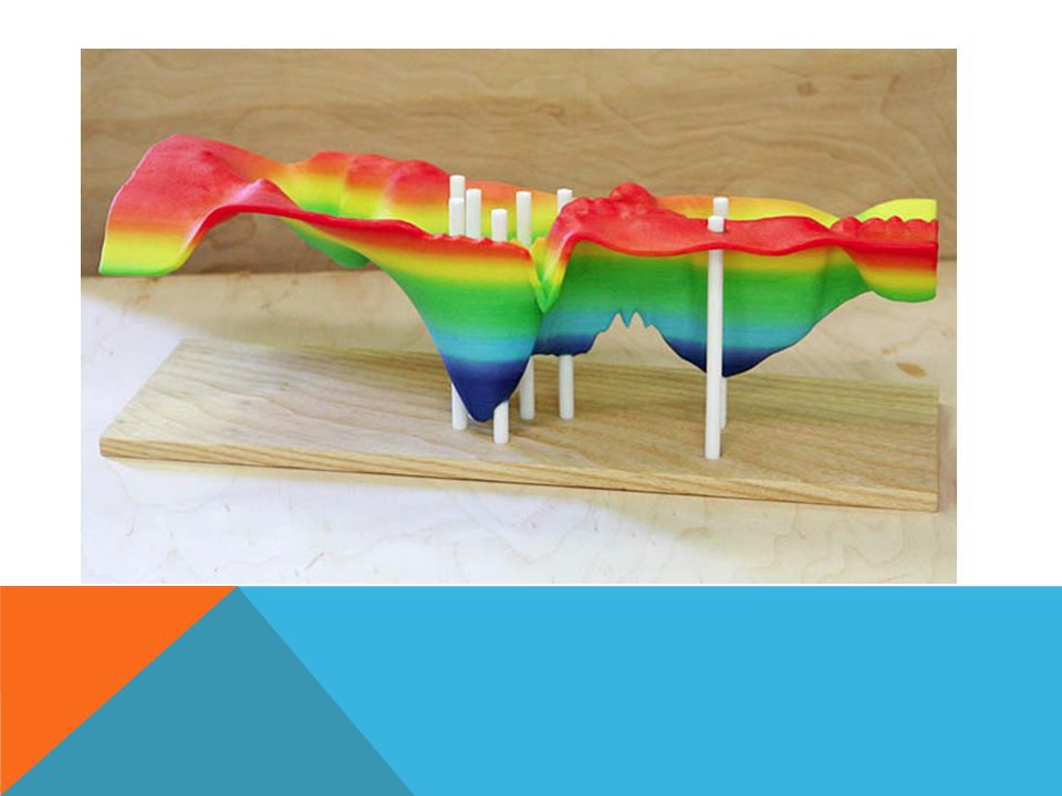
These are the few tomography models we set out to print
These are the few tomography models we set out to print. The top images are Emilie Hoofts models for the Newberry Magma body, the lower tomo is Max Bezadas model of a subducted slab in the Mediterranean. Now these models were easy to convert. if you already have your object in the 3 dimensional field in MATLAB, the following steps are not necessary and you can simply call a user-defined function to obtain your converted file. This function Requires that you must have an FV patch defined somewhere in your script. But if you are trying to create an object from a simple surface mesh, the following work must be done manually in MATLAB to create an object with the proper handles.

6
MatLab Logo: The L-Shaped Membrane
The first step in translating a matrix based plot into an STL file is to break up each square element in the mesh into two triangular elements. We can make use of the function DELAUNAY to create a Delauney triangulation of the rectilinar mesh. Notice That the mesh has no thickness…. 1) Break up each square element in the mesh into two triangular elements using the MatLab function Delauney. Notice That the mesh has no thickness….
 Break up each square element in the mesh into two triangular elements using the MatLab function Delauney. Notice That the mesh has no thickness…. s_eid=PSM_4977#1f9d71f d7-a639-a e.")
7
3) Creates a second surface with no thickness beneath the original.
Make a shell out of the surface by projecting all the vertices of the triangles downward along normal vectors to create a second surface with no thickness beneath the original. Then connect the two surfaces along their boundaries to define a third surface. 2) Make a shell out of the surface by projecting all the vertices of the triangles downward along normal vectors. 3) Creates a second surface with no thickness beneath the original. 4) Connect the two surfaces along their boundaries to define a third surface.
 Make a shell out of the surface by projecting all the vertices of the triangles downward along normal vectors. 3) Creates a second surface with no thickness beneath the original. 4) Connect the two surfaces along their boundaries to define a third surface. s_eid=PSM_4977#1f9d71f d7-a639-a e.")
8
STLWRITE Creates STL file directly from .m script
Downloadable function created for MatLab that exports a binary STL (or ascii) formatted version of a script. Requires that your code have triangulated patch called FV, a structure with fields ‘vertices’ and ‘faces’. STLWRite pretty much did our work for us. Its essentially the code we sought to develop, but we happened to find it on mathworks and downloaded it, saved us a lot of trouble. Luckily the model I was working on already had an FV patch, and the process was simply a matter of calling the function stlwrite. stlwrite (filename , FV)
 formatted version of a script. Requires that your code have triangulated patch called FV, a structure with fields ‘vertices’ and ‘faces’. STLWRite pretty much did our work for us. Its essentially the code we sought to develop, but we happened to find it on mathworks and downloaded it, saved us a lot of trouble. Luckily the model I was working on already had an FV patch, and the process was simply a matter of calling the function stlwrite. stlwrite (filename , FV)")
9
Additional Steps STL file now needs to be sliced
Software called “Slic3r” (and others) cuts file up into 2-dimensional cross sections of data, readable by printer Some printers read another basic format called G-Code. If that’s the case when you go to print, this software will generate a G-Code from your STL file. Use MeshLab for a 3D preview
 cuts file up into 2-dimensional cross sections of data, readable by printer. Some printers read another basic format called G-Code. If that’s the case when you go to print, this software will generate a G-Code from your STL file. Use MeshLab for a 3D preview.")
10
Applications

14
Interested in Printing?
Eugene MakerSpace has printers for public use Possibly getting a printer in the geophysics department me if you’re interested in printing something or would like more info on how to prepare your model for a printer.

15
Links Slic3r Downloadable STL files STL WRITE Meshlab
MatLab L-Shaped Membrane Steps STL WRITE Meshlab Slic3r Downloadable STL files

Similar presentations


 drawing. With the use.>")


