Download presentation
Presentation is loading. Please wait.

1
ILC Cryomodule Earthquake response simulation H. Hayano, H. Nakai, Y. Yamamoto 11142013 LCWS13 AWG7-SCRF

2
(1)Creation of FEM model (2)Static analysis (3)Eigen-mode analysis (4)Earthquake Response analysis by ISO3010 Analysis by ANSYS ver14.0,
Creation of FEM model (2)Static analysis (3)Eigen-mode analysis (4)Earthquake Response analysis by ISO3010 Analysis by ANSYS ver14.0,")
3
FEM model creation Modeling of one cryomodule with both end-plate (connected cryomodule will be done later.)
")
4
Basement: FNAL T4CM, Quadrupole magnet in the center

6
Generated Mesh Vessel, GRP, cavities, magnet : represented by shell element Screw bolts : represented by beam element Beam pipes, coupler, GRP-end : represented by spring element

7
Generated Mesh in detail-01

8
Generated Mesh in detail-02 Base surface of the mount Is fixed to the floor Double shields are represented by the weight around support post Gate valves are represented by the weight at GRP ends

9
The list of components: material, young-coefficient, poisson ratio, density

10
The list of components: material, volume, density, weight Total model weight is 9.00t

11
Eigen-mode Analysis

12
X: beam axis Y: vertical axis Z: horizontal axis The list of eigen-mode

13
Main mode of X-direction (beam axis) : 10.76Hz
 : 10.76Hz")
14
Main mode of Y-direction (vertical axis) : 19.75Hz
 : 19.75Hz")
15
Main mode of Z-direction (horizontal axis) : 6.67Hz
 : 6.67Hz")
16
Static analysis

17
Static: Vacuum Vessel displacement

18
Static: GRP and Cavities displacement

19
Static: Vacuum Vessel Stress

20
Static: GRP Stress

21
Earthquake Response analysis by ISO-3010

22
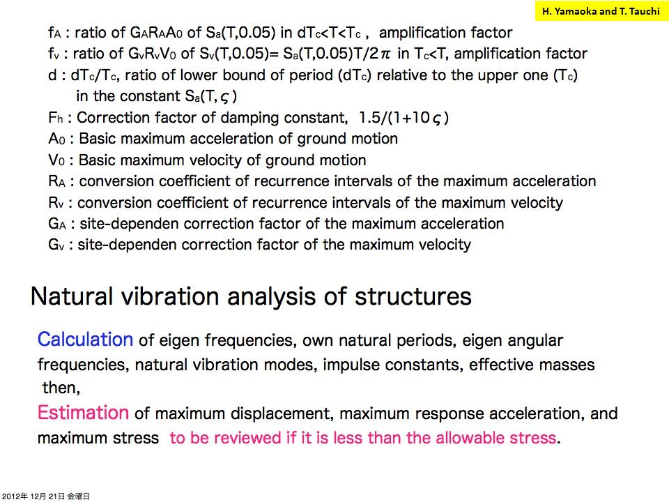
H. Yamaoka and T. Tauchi 150 gal in Kitakami

23
H. Yamaoka and T. Tauchi

28
Three main Eigen-modes ISO-3010 Earthquake Spectrum Assumed spectrum; 100 years endurance, at Tsukuba surface ( medium rigidity) (and at Kitakami-site surface) 200 gals is representative earthquake, peak acceleration is 900 gals at 0.28 – 0.8 sec period ( 1.25Hz - 3.57Hz ) Assumed spectrum (red line)
 (and at Kitakami-site surface) 200 gals is representative earthquake, peak acceleration is 900 gals at 0.28 – 0.8 sec period ( 1.25Hz Hz ) Assumed spectrum (red line)")
29
Stress Analysis applying earthquake spectrum

30
(1) M24 adjustable bolts of the support post (2) M24 adjustable bolts of vacuum vessel basement Max. stress for beam-elements by static + Earthquake Max. allowable stress of steel and stainless-steel is 200MPa Components excessing max. allowable stress are;

31
(3) Interface plates between GRP and support post Max. allowable stress of steel and stainless-steel is 200MPa Components excessing max. allowable stress are; Max. stress for shell-elements by static + Earthquake

32
Interface plates bottom surface movement More detail explanation of max stress: (3) Interface plates between GRP and support post Interface plates top surface Max. stress for shell-elements by 10.76Hz Eigen-mode (beam axis direction mode) Fixed support post
 Fixed support post.")
33
Summary of Analysis ILC cryomodule based on T4CM(FNAL) was modeled for FEM analysis. The Eigen-modes are; 10.76 Hz for X axis (electron beam direction) 19.75 Hz for Y axis (vertical direction) 6.67 Hz for Z axis (horizontal direction) Earthquake spectrum based on ISO-3010 was assumed for; 100 years recurrence, 200 gal acceleration at Tsukuba area rigidity. ( It corresponds to 150 gal at Kitakami area, smaller than Tsukuba ) (1) M24 adjustable bolts of the support post (360MPa) (2) M24 adjustable bolts of vacuum vessel basement (399MPa) (3) Interface plates between GRP and support post (318MPa) Components excessing max. allowable stress (200MPa) are; Need size-up of M24 bolts, additional support for the GRP-support post interface plate. Their cost-up will not be so much.
 Hz for Y axis (vertical direction) 6.67 Hz for Z axis (horizontal direction) Earthquake spectrum based on ISO-3010 was assumed for; 100 years recurrence, 200 gal acceleration at Tsukuba area rigidity. ( It corresponds to 150 gal at Kitakami area, smaller than Tsukuba ) (1) M24 adjustable bolts of the support post (360MPa) (2) M24 adjustable bolts of vacuum vessel basement (399MPa) (3) Interface plates between GRP and support post (318MPa) Components excessing max. allowable stress (200MPa) are; Need size-up of M24 bolts, additional support for the GRP-support post interface plate. Their cost-up will not be so much..")
Similar presentations


 2. High Pressure Code, 5K Shield (Tom Peterson)>")


