Download presentation
Presentation is loading. Please wait.

1
Combustion Sources

2
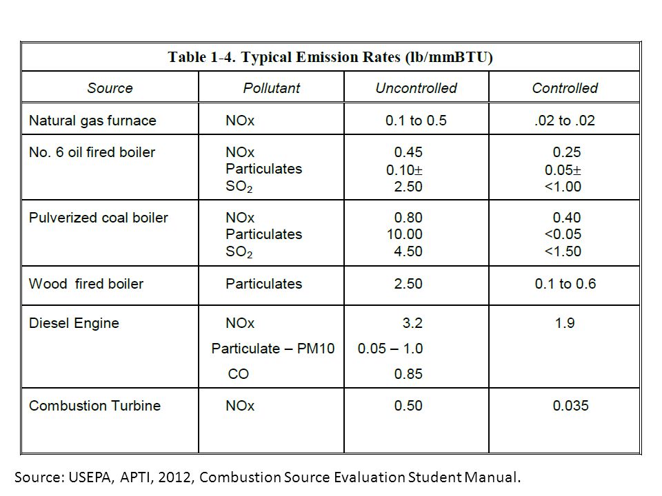
Source: USEPA, APTI, 2012, Combustion Source Evaluation Student Manual.

4
Emissions from combustion sources can be broken into three groups: 1. Products of incomplete combustion or PIC (CO, carbon, organic species) 2. Emissions formed from fuel contaminants (SOx, particulates, etc.) 3. Nitrogen oxides (NOx) Source: USEPA, APTI, 2012, Combustion Source Evaluation Student Manual.
 2. Emissions formed from fuel contaminants (SOx, particulates, etc.) 3. Nitrogen oxides (NOx) Source: USEPA, APTI, 2012, Combustion Source Evaluation Student Manual..")
6
Internal Combustion Engines The term “engine” in this course includes two types of power source: (1) reciprocating engines and (2) combustion turbines (CT), also called gas turbines. Both are internal combustion (IC) devices in which the exhaust gases directly drive the power production hardware. Stationary engines serve a number of common purposes including: emergency (stand-by) power generation, pipeline pumping and, increasingly, electric utility generators. Nearly all stationary engines burn clean fuels such as natural gas, or distillate oil, such as diesel or No. 2 oil. Therefore, the emission species of primary concern is NOx. The basic configuration of an engine is that it has a fuel supply line on one end and a power output shaft on the other. A single manufacturer ships a package that converts fuel to mechanical power. Source: USEPA, APTI, 2012, Combustion Source Evaluation Student Manual.
 devices in which the exhaust gases directly drive the power production hardware. Stationary engines serve a number of common purposes including: emergency (stand-by) power generation, pipeline pumping and, increasingly, electric utility generators. Nearly all stationary engines burn clean fuels such as natural gas, or distillate oil, such as diesel or No. 2 oil. Therefore, the emission species of primary concern is NOx. The basic configuration of an engine is that it has a fuel supply line on one end and a power output shaft on the other. A single manufacturer ships a package that converts fuel to mechanical power. Source: USEPA, APTI, 2012, Combustion Source Evaluation Student Manual..")
7
Operating Principle of a Reciprocating Engine Source: USEPA, APTI, 2012, Combustion Source Evaluation Student Manual.

9
Components of a Combustion Turbine Source: USEPA, APTI, 2012, Combustion Source Evaluation Student Manual.

10
GE H Series Gas Turbine, electrical power generation in combined cycle configuration, this 480-megawatt unit has a rated thermal efficiency of 60%. This image is from: http://en.wikipedia.org/wiki/File:GE_ H_series_Gas_Turbine.jpg The basic operation of the gas turbine is similar to that of the steam power plant except that air is used instead of water. Fresh atmospheric air flows through a compressor that brings it to higher pressure. Energy is then added by spraying fuel into the air and igniting it so the combustion generates a high-temperature flow. This high-temperature high- pressure gas enters a turbine, where it expands down to the exhaust pressure, producing a shaft work output in the process. The turbine shaft work is used to drive the compressor and other devices such as an electric generator that may be coupled to the shaft. The energy that is not used for shaft work comes out in the exhaust gases, so these have either a high temperature or a high velocity. The purpose of the gas turbine determines the design so that the most desirable energy form is maximized. Gas turbines are used to power aircraft, trains, ships, electrical generators, or even tanks. http://en.wikipedia.org/wiki/Gas_turbine

11
Combined Cycles ( 複循環 ) Source: USEPA, APTI, 2012, Combustion Source Evaluation Student Manual.
 Source: USEPA, APTI, 2012, Combustion Source Evaluation Student Manual.")
12
Combined Cycles Engines typically have thermal efficiencies of 30% to 40%; that is, the amount of fuel energy that is actually converted into shaft power. More than half of the energy is lost. Combined cycle is a term used to describe a power system in which the waste heat from the primary engine is used to drive another power source. Waste energy in the exhaust gas from an engine is used to heat a boiler that drives a steam turbine. The efficiency is increased from perhaps 35% for the engine alone to about 50% for the combined cycle system. Source: USEPA, APTI, 2012, Combustion Source Evaluation Student Manual.

13
When the waste heat from a turbine or engine is used directly for heating, the system is called cogeneration. Cogeneration was fairly common in the first half of the 20th century, but gradually disappeared with the evolution of huge electric generating plants. However, cogeneration has seen a resurgence in recent years at college campuses, factory complexes and some urban centers where there is a significant demand for heat. Cogeneration ( 汽電共生 ) Source: USEPA, APTI, 2012, Combustion Source Evaluation Student Manual.
 Source: USEPA, APTI, 2012, Combustion Source Evaluation Student Manual..")
14
Boiler Systems Boilers are the most common stationary combustion source. They are present in most factories and are at the heart of the nation’s electric supply system. The boiler is an “external” combustion device because the exhaust gases do not contact the turbine that produces mechanical power. Fire heats water until it boils and the steam is piped off for various uses. Boilers are built as part of a system, so the steam is piped into a factory process that requires heat, or it is piped to a turbine that drives a pump or an electric power generator. Source: USEPA, APTI, 2012, Combustion Source Evaluation Student Manual.

15
Comparative Sizes of Boilers Source: USEPA, APTI, 2012, Combustion Source Evaluation Student Manual.

17
Basic Burner Design Source: USEPA, APTI, 2012, Combustion Source Evaluation Student Manual.

18
Typical Large Burner Source: USEPA, APTI, 2012, Combustion Source Evaluation Student Manual.

19
Elements of a Pulverized Coal System Source: USEPA, APTI, 2012, Combustion Source Evaluation Student Manual.

20
Stoker( 供煤機 ) Firing Concept Source: USEPA, APTI, 2012, Combustion Source Evaluation Student Manual.
 Firing Concept Source: USEPA, APTI, 2012, Combustion Source Evaluation Student Manual.")
21
Example Configurations of Industrial Stokers Source: USEPA, APTI, 2012, Combustion Source Evaluation Student Manual.

22
Stoker in a Large Boiler Source: USEPA, APTI, 2012, Combustion Source Evaluation Student Manual.

23
Fluidized Bed Combustor Source: USEPA, APTI, 2012, Combustion Source Evaluation Student Manual.

24
Cement Kilns. These are large combustors used to manufacture Portland cement – the key ingredient of concrete. They are well adapted to burn a wide range of fuels and generally burn the cheapest fuel available. Because they must operate at very high temperatures in order to make their product, a number of them are used to incinerate hazardous waste. There are also lime kilns that are similar to cement kilns, but they are usually smaller and operate at lower temperatures. Cement and lime kilns process limestone (CaCO3) to generate lime (CaO), so they emit large amounts of CO2 from the process in addition to the CO2 from combustion. Rotating Cement Kiln Source: USEPA, APTI, 2012, Combustion Source Evaluation Student Manual.
 to generate lime (CaO), so they emit large amounts of CO2 from the process in addition to the CO2 from combustion. Rotating Cement Kiln Source: USEPA, APTI, 2012, Combustion Source Evaluation Student Manual..")
25
Solid Waste Incinerators. In most cases, the combustor is a boiler where waste is the fuel and the facility is called a municipal waste- to-energy plant. This avoids the stigma associated with the word incinerator. The term incinerator is generally reserved for facilities where there is no energy recovery. Waste water treatment plants generate solid sludge, which, in many cases, is fed to a sludge incinerator. Recently designed units operate cleanly, but the older ones can be a significant source of air pollution. Source: USEPA, APTI, 2012, Combustion Source Evaluation Student Manual.

26
Multiple Hearth Sludge Burner Source: USEPA, APTI, 2012, Combustion Source Evaluation Student Manual.

27
Hazardous Waste Incinerators. Combustible waste that is legally defined as hazardous is required to go to a facility that is licensed to burn it. All facilities that burn waste must demonstrate their ability to safely manage the waste. There are extensive monitoring requirements designed to ensure compliance. However, the legal classification of a waste may have no relation to its combustion characteristics. Some hazardous substances, such as benzene, burn quite easily and cleanly, while other non-hazardous fuels, such as wet wood chips, can be a source of substantial air pollution and, sometimes, hazardous substances. During normal operation, all modern incinerators achieve nearly 100% destruction (complete combustion) of organic waste. Thermal Oxidizers. This term is commonly used for combustors that consume organic vapors such as solvents, phenols, etc. emitted by industrial facilities. Thermal oxidizers are pollution control devices that consume fuel without making any steam or useful energy. When designed and operated properly, they consume essentially 100% of the target pollutants and their only significant emissions may be NOx. Source: USEPA, APTI, 2012, Combustion Source Evaluation Student Manual.
 of organic waste. Thermal Oxidizers. This term is commonly used for combustors that consume organic vapors such as solvents, phenols, etc. emitted by industrial facilities. Thermal oxidizers are pollution control devices that consume fuel without making any steam or useful energy. When designed and operated properly, they consume essentially 100% of the target pollutants and their only significant emissions may be NOx. Source: USEPA, APTI, 2012, Combustion Source Evaluation Student Manual..")
28
Thermal Oxidizer (Gas Incinerator) Source: USEPA, APTI, 2012, Combustion Source Evaluation Student Manual.
 Source: USEPA, APTI, 2012, Combustion Source Evaluation Student Manual.")
29
Ground Flare Concept Source: USEPA, APTI, 2012, Combustion Source Evaluation Student Manual.

Similar presentations


 IGCC is basically the combination of the gasification unit and the combined cycle. It has high efficiency.>")


 燃料脫硫 (fuel desulfurization, removal of sulfur from fuel) 排煙脫硫 (flue gas desulfurization, FGD)>")


