Download presentation
Presentation is loading. Please wait.

1
Foundations of Computer Graphics (Spring 2012) CS 184, Lecture 21: Radiometry http://inst.eecs.berkeley.edu/~cs184 Many slides courtesy Pat Hanrahan
 CS 184, Lecture 21: Radiometry Many slides courtesy Pat Hanrahan")
2
Overview Lighting and shading key in computer graphics HW 2 etc. ad-hoc shading models, no units Really, want to match physical light reflection Next 3 lectures look at this formally Today: physical measurement of light: radiometry Formal reflection equation, reflectance models Global Illumination (later)
.")
4
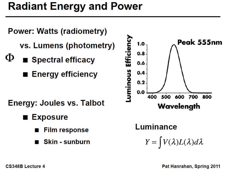
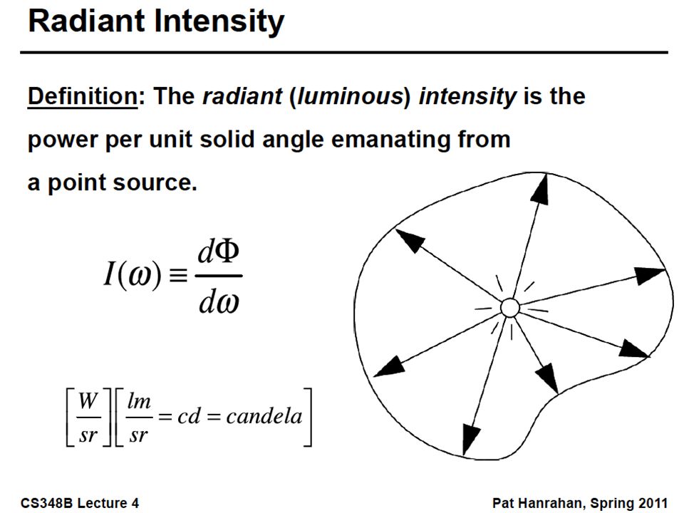
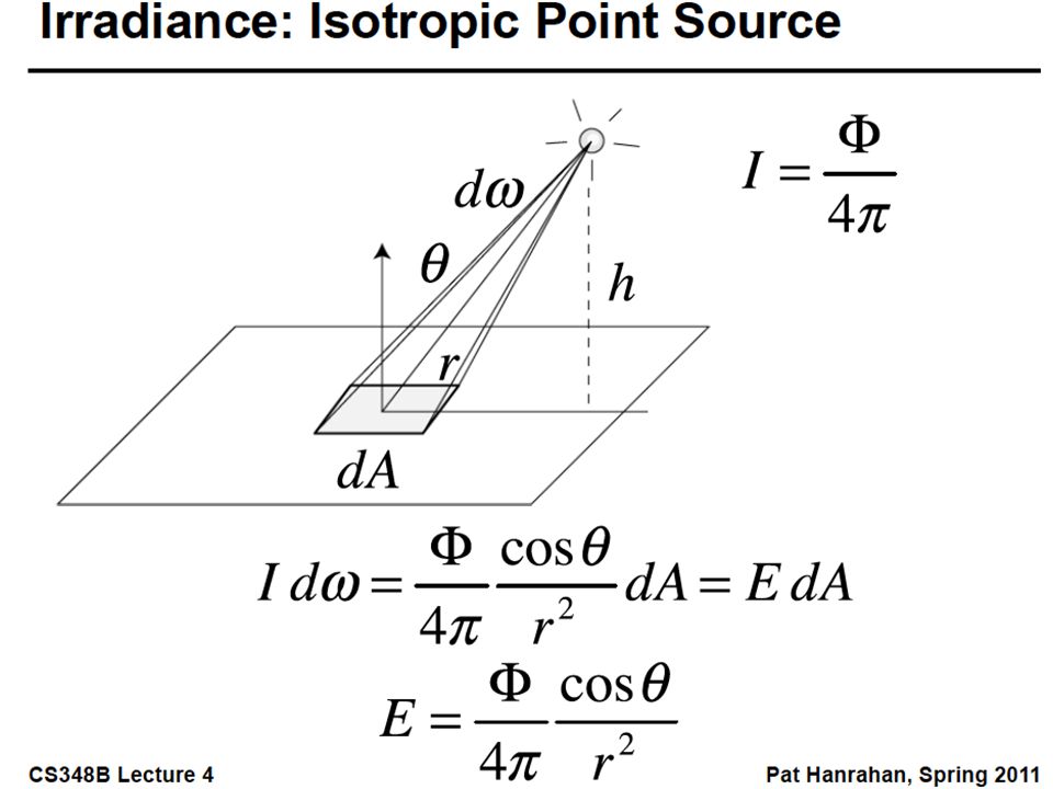
Radiometry and Photometry Physical measurement of electromagnetic energy Measure spatial (and angular) properties of light Radiant Power Radiant Intensity Irradiance Inverse square and cosine law Radiance Radiant Exitance (Radiosity) Reflection functions: Bi-Directional Reflectance Distribution Function or BRDF Reflection Equation
 properties of light Radiant Power Radiant Intensity Irradiance Inverse square and cosine law Radiance Radiant Exitance (Radiosity) Reflection functions: Bi-Directional Reflectance Distribution Function or BRDF Reflection Equation")
13
Radiometry and Photometry Physical measurement of electromagnetic energy Measure spatial (and angular) properties of light Radiant Power Radiant Intensity Irradiance Inverse square and cosine law Radiance Radiant Exitance (Radiosity) Reflection functions: Bi-Directional Reflectance Distribution Function or BRDF Reflection Equation
 properties of light Radiant Power Radiant Intensity Irradiance Inverse square and cosine law Radiance Radiant Exitance (Radiosity) Reflection functions: Bi-Directional Reflectance Distribution Function or BRDF Reflection Equation")
20
Radiometry and Photometry Physical measurement of electromagnetic energy Measure spatial (and angular) properties of light Radiant Power Radiant Intensity Irradiance Inverse square and cosine law Radiance Radiant Exitance (Radiosity) Reflection functions: Bi-Directional Reflectance Distribution Function or BRDF Reflection Equation
 properties of light Radiant Power Radiant Intensity Irradiance Inverse square and cosine law Radiance Radiant Exitance (Radiosity) Reflection functions: Bi-Directional Reflectance Distribution Function or BRDF Reflection Equation")
21
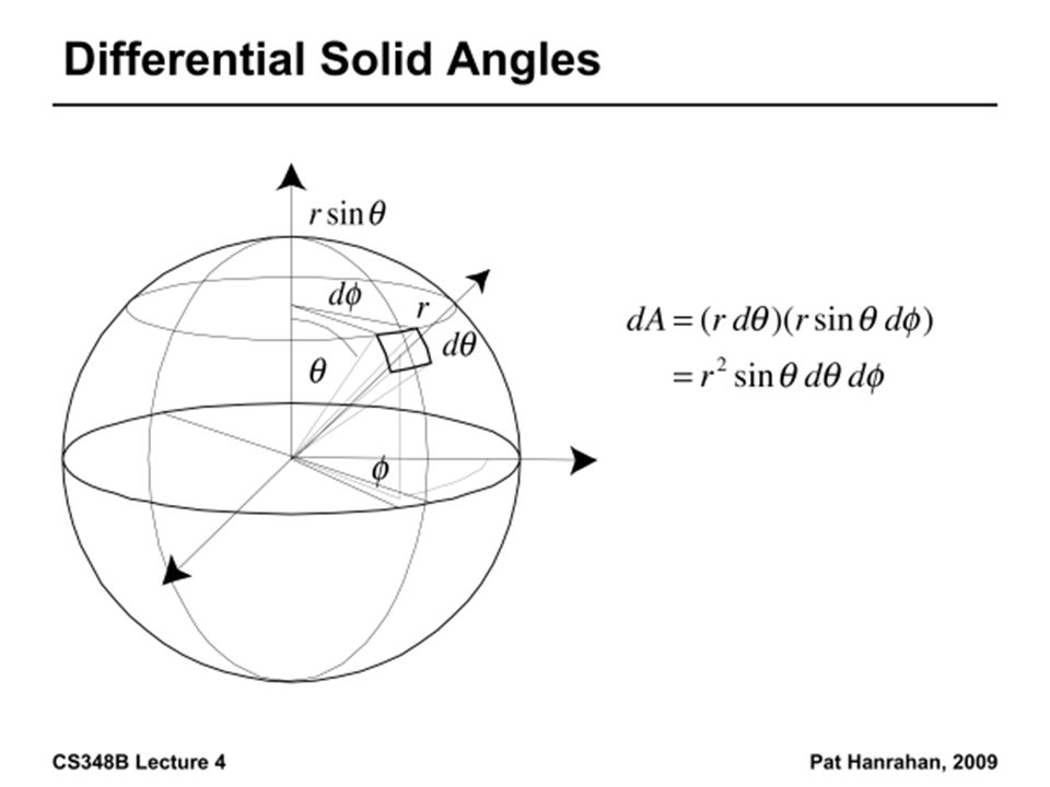
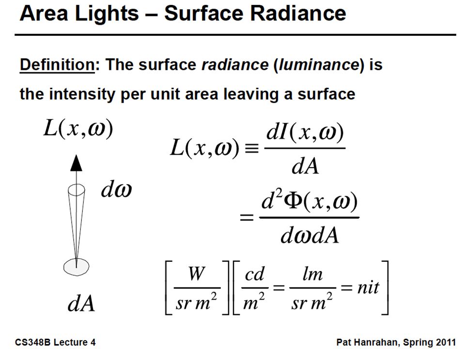
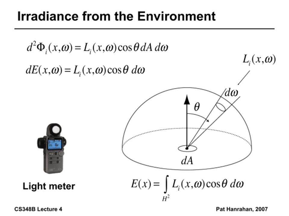
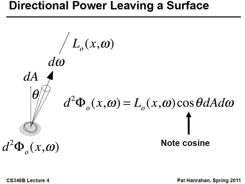
Radiance Power per unit projected area perpendicular to the ray per unit solid angle in the direction of the ray Symbol: L(x,ω) (W/m 2 sr) Flux given by dΦ = L(x,ω) cos θ dω dA
 (W/m 2 sr) Flux given by dΦ = L(x,ω) cos θ dω dA")
24
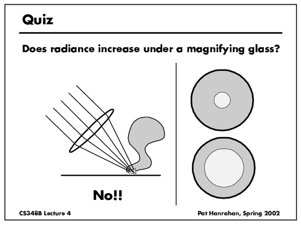
Radiance properties Radiance constant as propagates along ray –Derived from conservation of flux –Fundamental in Light Transport.

27
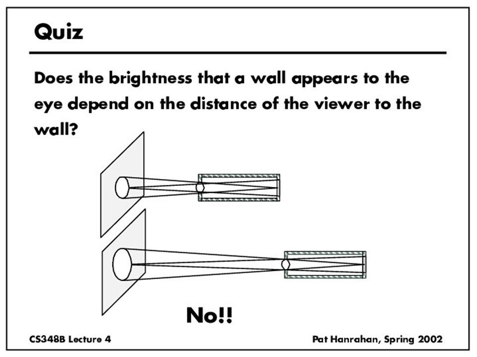
Radiance properties Sensor response proportional to radiance (constant of proportionality is throughput) –Far surface: See more, but subtend smaller angle –Wall equally bright across viewing distances Consequences –Radiance associated with rays in a ray tracer –Other radiometric quants derived from radiance
 –Far surface: See more, but subtend smaller angle –Wall equally bright across viewing distances Consequences –Radiance associated with rays in a ray tracer –Other radiometric quants derived from radiance")
28
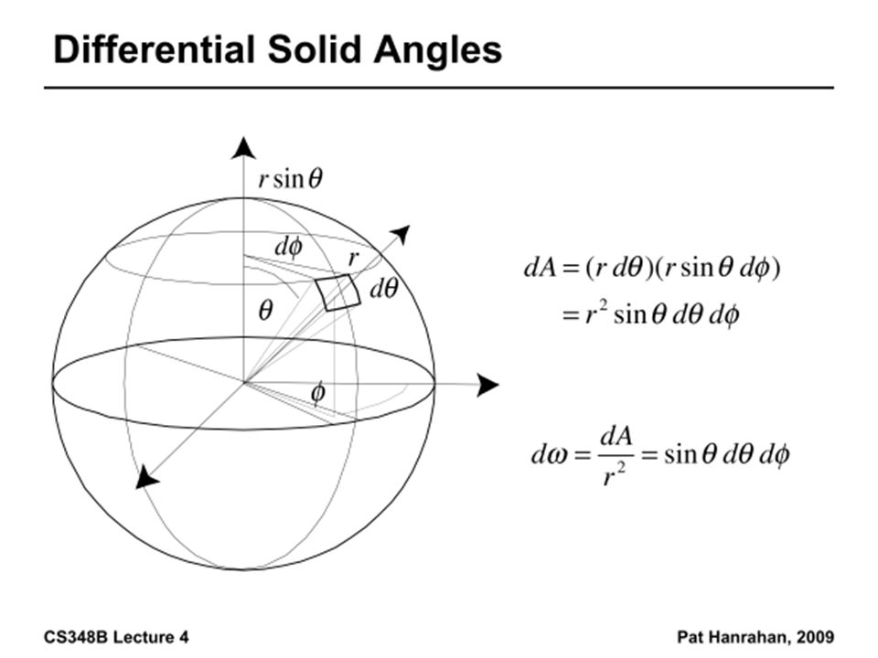
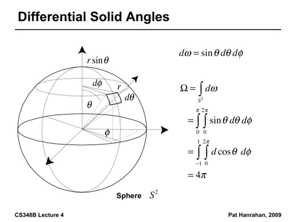
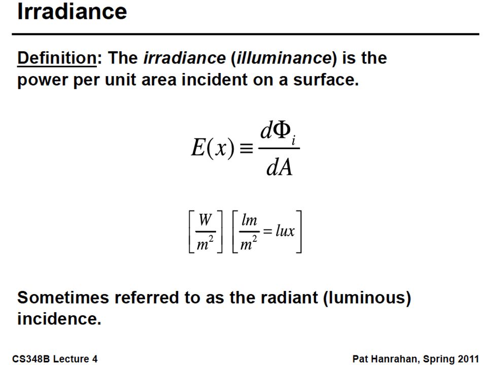
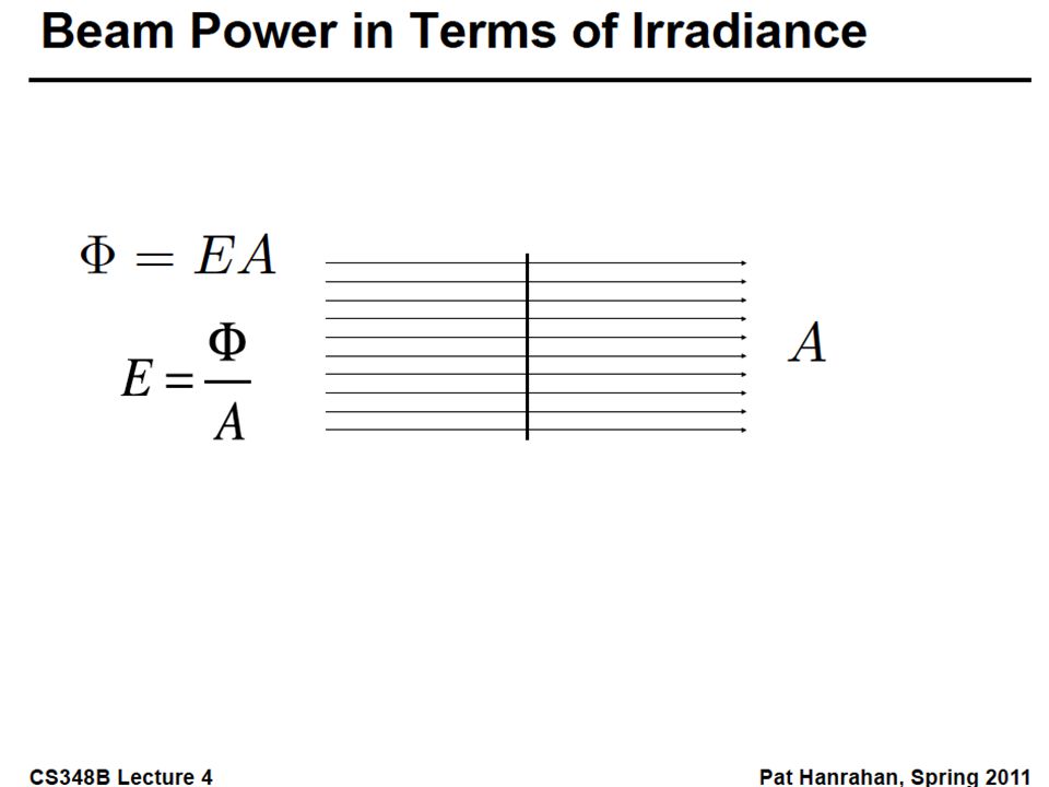
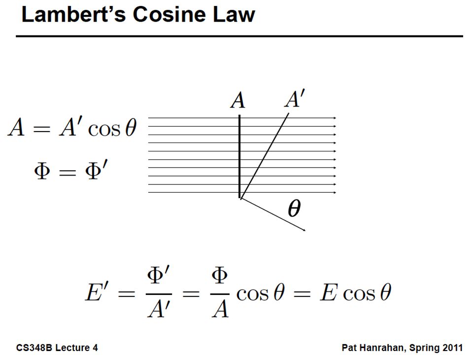
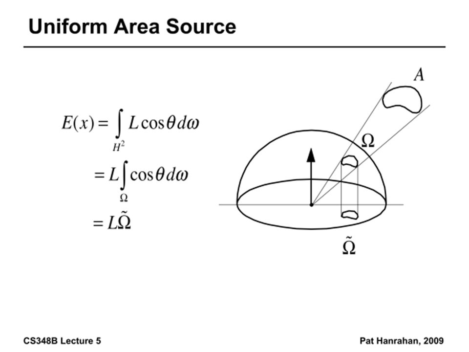
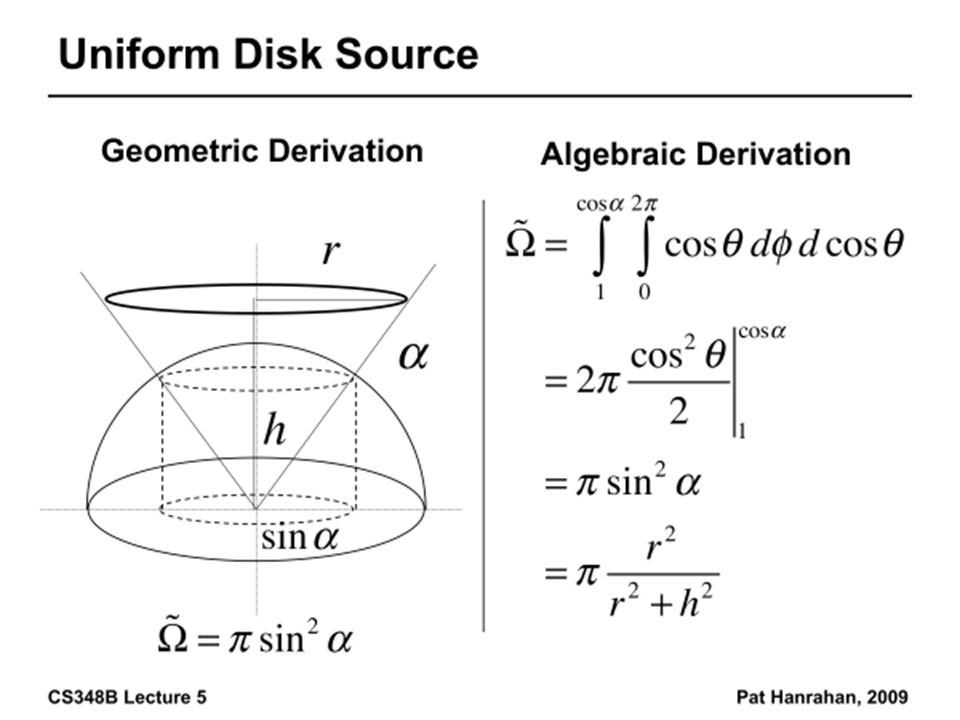
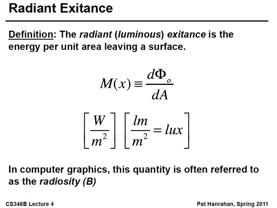
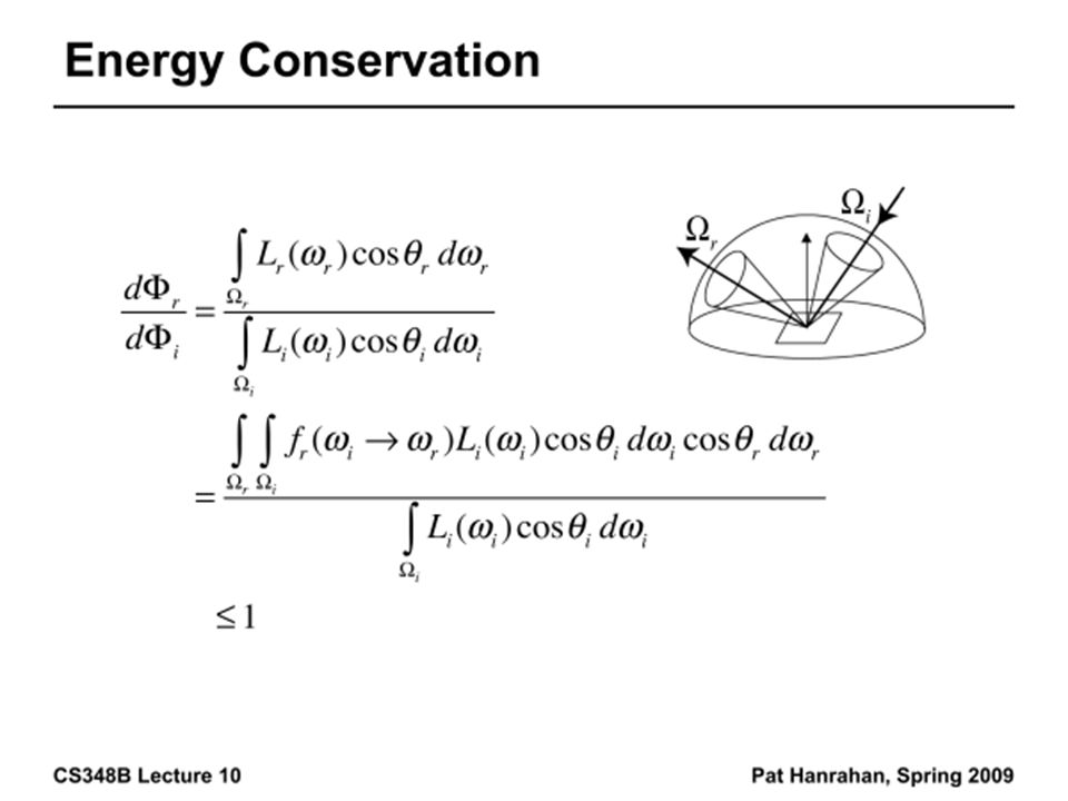
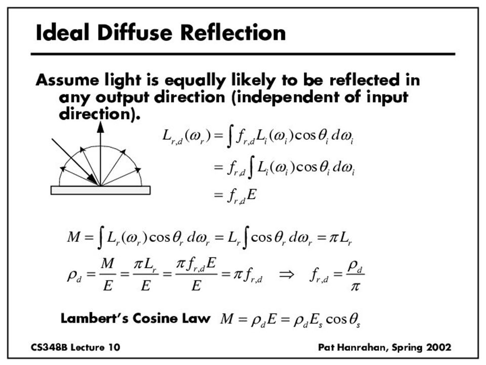
Irradiance, Radiosity Irradiance E is radiant power per unit area Integrate incoming radiance over hemisphere –Projected solid angle (cos θ dω) –Uniform illumination: Irradiance = π [CW 24,25] –Units: W/m 2 Radiant Exitance (radiosity) –Power per unit area leaving surface (like irradiance)
![Irradiance, Radiosity Irradiance E is radiant power per unit area Integrate incoming radiance over hemisphere –Projected solid angle (cos θ dω) –Uniform illumination: Irradiance = π [CW 24,25] –Units: W/m 2 Radiant Exitance (radiosity) –Power per unit area leaving surface (like irradiance)](http://images.slideplayer.com/14/4490555/slides/slide_28.jpg "Irradiance, Radiosity Irradiance E is radiant power per unit area Integrate incoming radiance over hemisphere –Projected solid angle (cos θ dω) –Uniform illumination: Irradiance = π [CW 24,25] –Units: W/m 2 Radiant Exitance (radiosity) –Power per unit area leaving surface (like irradiance)")
32
Irradiance Environment Maps Incident Radiance (Illumination Environment Map) Irradiance Environment Map R N
 Irradiance Environment Map R N")
35
Radiometry and Photometry Physical measurement of electromagnetic energy Measure spatial (and angular) properties of light Radiant Power Radiant Intensity Irradiance Inverse square and cosine law Radiance Radiant Exitance (Radiosity) Reflection functions: Bi-Directional Reflectance Distribution Function or BRDF Reflection Equation
 properties of light Radiant Power Radiant Intensity Irradiance Inverse square and cosine law Radiance Radiant Exitance (Radiosity) Reflection functions: Bi-Directional Reflectance Distribution Function or BRDF Reflection Equation")
39
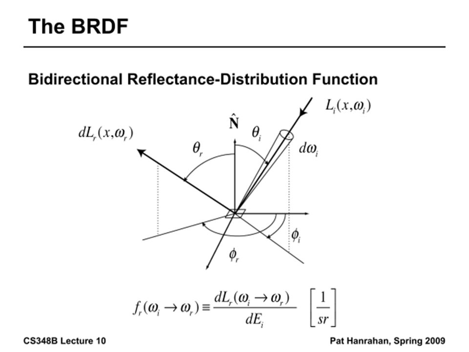
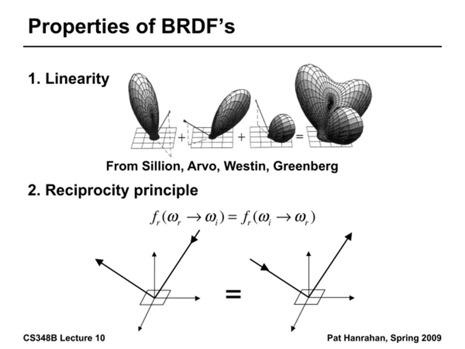
Building up the BRDF Bi-Directional Reflectance Distribution Function [Nicodemus 77] Function based on incident, view direction Relates incoming light energy to outgoing Unifying framework for many materials
![Building up the BRDF Bi-Directional Reflectance Distribution Function [Nicodemus 77] Function based on incident, view direction Relates incoming light energy to outgoing Unifying framework for many materials](http://images.slideplayer.com/14/4490555/slides/slide_39.jpg "Building up the BRDF Bi-Directional Reflectance Distribution Function [Nicodemus 77] Function based on incident, view direction Relates incoming light energy to outgoing Unifying framework for many materials")
41
BRDF Reflected Radiance proportional Irradiance Constant proportionality: BRDF Ratio of outgoing light (radiance) to incoming light (irradiance) –Bidirectional Reflection Distribution Function –(4 Vars) units 1/sr
 to incoming light (irradiance) –Bidirectional Reflection Distribution Function –(4 Vars) units 1/sr")
44
Isotropic vs Anisotropic Isotropic: Most materials (you can rotate about normal without changing reflections) Anisotropic: brushed metal etc. preferred tangential direction Isotropic Anisotropic

45
Radiometry and Photometry Physical measurement of electromagnetic energy Measure spatial (and angular) properties of light Radiant Power Radiant Intensity Irradiance Inverse square and cosine law Radiance Radiant Exitance (Radiosity) Reflection functions: Bi-Directional Reflectance Distribution Function or BRDF Reflection Equation (and simple BRDF models)
 properties of light Radiant Power Radiant Intensity Irradiance Inverse square and cosine law Radiance Radiant Exitance (Radiosity) Reflection functions: Bi-Directional Reflectance Distribution Function or BRDF Reflection Equation (and simple BRDF models)")
46
Reflection Equation Reflected Light (Output Image) Emission Incident Light (from light source) BRDF Cosine of Incident angle
 Emission Incident Light (from light source) BRDF Cosine of Incident angle")
47
Reflection Equation Reflected Light (Output Image) Emission Incident Light (from light source) BRDF Cosine of Incident angle Sum over all light sources
 Emission Incident Light (from light source) BRDF Cosine of Incident angle Sum over all light sources")
48
Reflection Equation Reflected Light (Output Image) Emission Incident Light (from light source) BRDF Cosine of Incident angle Replace sum with integral
 Emission Incident Light (from light source) BRDF Cosine of Incident angle Replace sum with integral")
50
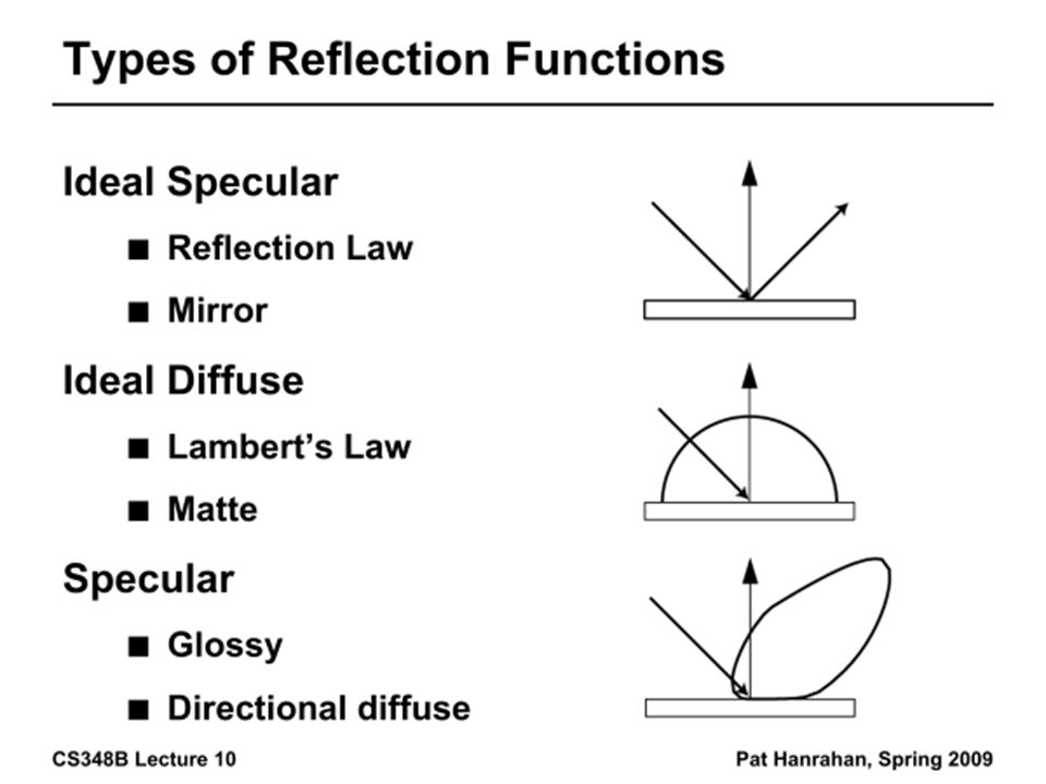
BRDF Viewer plots Diffuse bv written by Szymon Rusinkiewicz Torrance-Sparrow Anisotropic

55
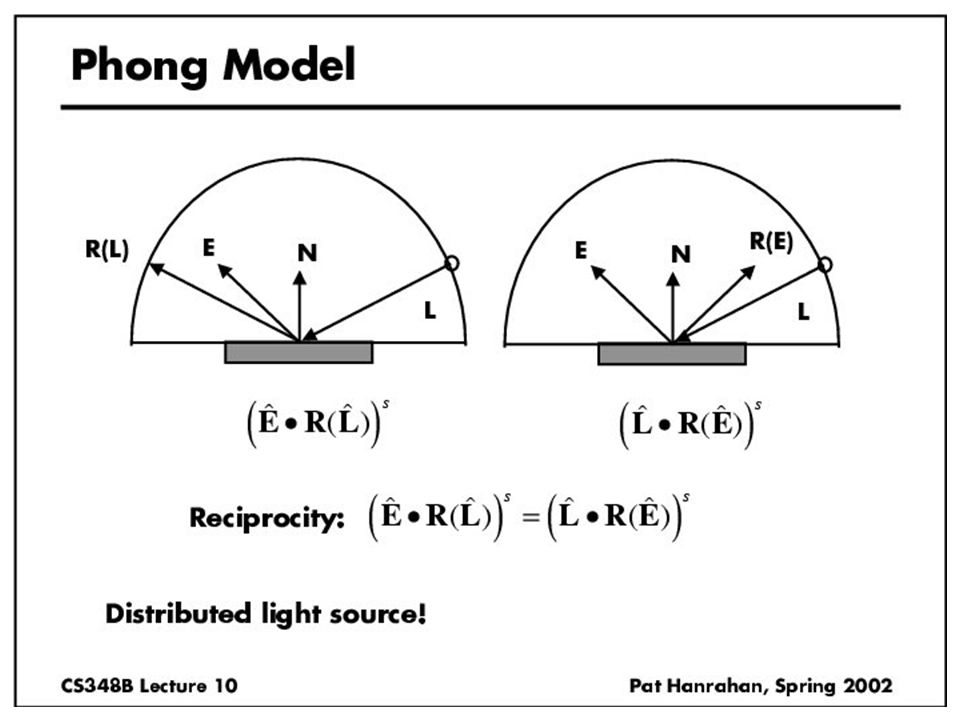
Analytical BRDF: TS example One famous analytically derived BRDF is the Torrance-Sparrow model T-S is used to model specular surface, like Phong more accurate than Phong has more parameters that can be set to match different materials derived based on assumptions of underlying geometry. (instead of ‘because it works well’)
.")
56
Torrance-Sparrow Assume the surface is made up grooves at microscopic level. Assume the faces of these grooves (called microfacets) are perfect reflectors. Take into account 3 phenomena Shadowing MaskingInterreflection
 are perfect reflectors. Take into account 3 phenomena Shadowing MaskingInterreflection.")
57
Torrance-Sparrow Result Fresnel term: allows for wavelength dependency Geometric Attenuation: reduces the output based on the amount of shadowing or masking that occurs. Distribution: distribution function determines what percentage of microfacets are oriented to reflect in the viewer direction. How much of the macroscopic surface is visible to the light source How much of the macroscopic surface is visible to the viewer

58
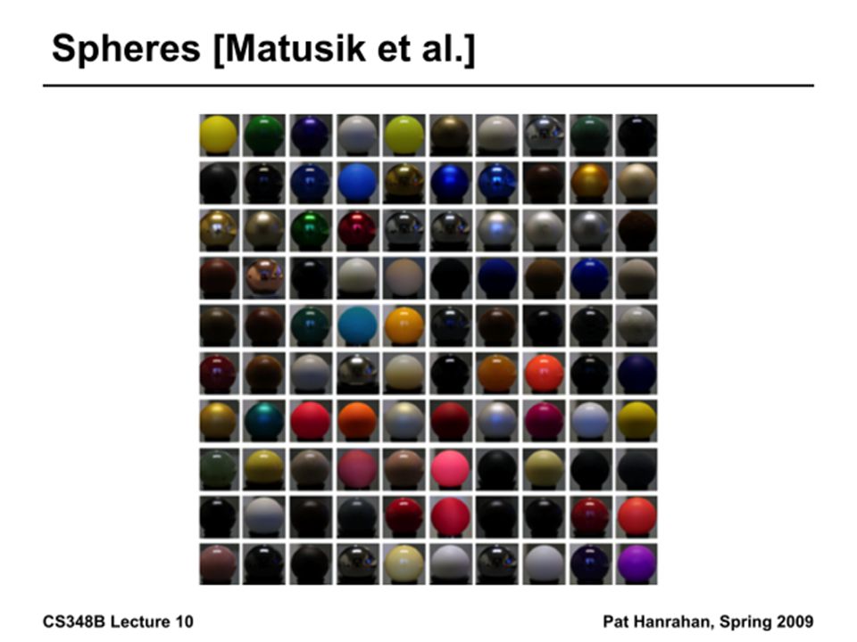
Other BRDF models Empirical: Measure and build a 4D table Anisotropic models for hair, brushed steel Cartoon shaders, funky BRDFs Capturing spatial variation Very active area of research

59
Environment Maps Light as a function of direction, from entire environment Captured by photographing a chrome steel or mirror sphere Accurate only for one point, but distant lighting same at other scene locations (typically use only one env. map) Blinn and Newell 1976, Miller and Hoffman, 1984 Later, Greene 86, Cabral et al. 87
 Blinn and Newell 1976, Miller and Hoffman, 1984 Later, Greene 86, Cabral et al. 87.")
60
Reflection Equation Reflected Light (Output Image) Emission Environment Map (continuous) BRDF Cosine of Incident angle Replace sum with integral
 Emission Environment Map (continuous) BRDF Cosine of Incident angle Replace sum with integral")
61
Environment Maps Environment maps widely used as lighting representation Many modern methods deal with offline and real-time rendering with environment maps Image-based complex lighting + complex BRDFs

62
Demo

Similar presentations


 COMS 4160, Lecture 18: Illumination and Shading 1>")


 CS 283, Lecture 8: Illumination and Reflection Many slides courtesy.>")


![Representations of Visual Appearance COMS 6160 [Fall 2006], Lecture 2 Ravi Ramamoorthi](/16/4942857/big_thumb.jpg "Representations of Visual Appearance COMS 6160 [Fall 2006], Lecture 2 Ravi Ramamoorthi>")
 COMS 4160, Lecture 20: Illumination and Shading 2>")