Download presentation
Presentation is loading. Please wait.

1
EQUILIBRIUM OF RIGID BODIES IN TWO DIMENSIONS

2
When a rigid body is in equilibrium, both the resultant force and the resultant couple must be zero.

3
Forces and moments acting on a rigid body could be external forces/moments or internal forces/moments. Forces acting from one body to another by direct physical contact or from the Earth are examples of external forces. Fluid pressure acting to the wall of a water tank or a force exerted by the tire of a truck to the road is all external forces.

4
The weight of a body is also an external force.
Internal forces, on the other hand, keep the particles which constitute the body intact. Since internal forces occur in pairs that are equal in magnitude opposite in direction, they are not considered in the equilibrium of rigid bodies. The first step in the analysis of the equilibrium of rigid bodies must be to draw the “free body diagram” of the body in question.

5
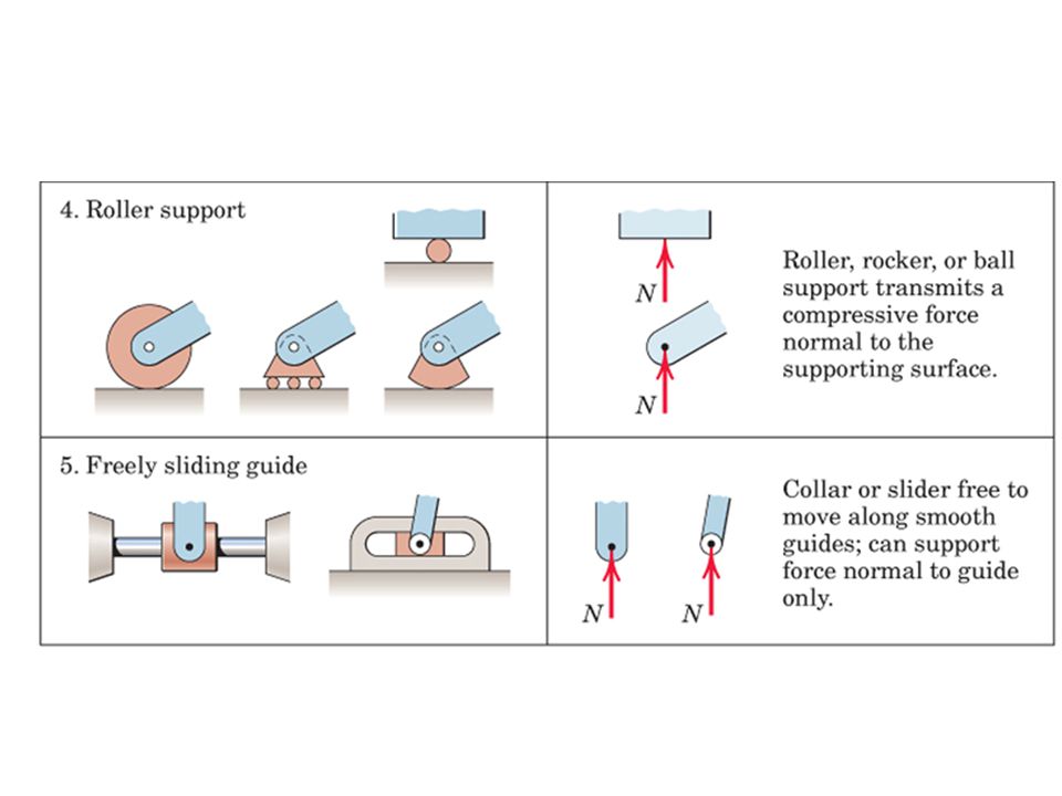
Common Support / Connection Element Types in Two Dimensional Analysis
In rigid bodies subjected to two dimensional force systems, the forces exerted from supports and connection elements are shown in the free body diagram as follows: It should be kept in mind that reaction will occur along the direction in which the motion of the body is restricted.

10
Equations of Equilibrium in Two Dimensional Case
If all the forces acting on the rigid body are planar and all the couples are perpendicular to the plane of the body, equations of equilibrium become two dimensional. or in scalar form, At most three unknowns can be determined.

11
Alternative Equations of Equilibrium
In two dimensional problems, in alternative to the above set of equations, two more sets of equations can be employed in the solution of problems. Points A, B and C in the latter set cannot lie along the same line, if they do, trivial equations will be obtained.

12
Examples of two force members
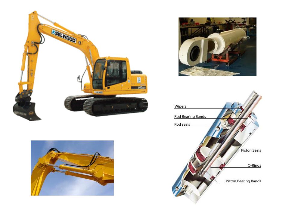
Members which are subjected to only two forces are named as “two force members”. Forces acting on these members are equal in magnitude, opposite in direction and are directed along the line joining the two points where the forces are applied. P By Bx Ax Ay FB FA=FB FA Weight is neglected. If weight is considered, the member will not be a two force member! B A P P P Examples of two force members P P P Hydraulic cylinder

14
Three-Force Member In rigid bodies acted on by only three forces, the lines of action of the forces must be concurrent; otherwise the body will rotate about the intersection point of the two forces due to the third force which is not concurrent. If the forces acting on the body are parallel, then the point of concurrency is assumed to be in infinity. A P B FA FB

15
Free Body Diagram The procedure for drawing a free body diagram which isolates a body or system consists of the following steps: If there exists, identify the two force members in the problem. Decide which system to isolate. Isolate the chosen system by drawing a diagram which represents its complete external boundary. If not given with the problem, select a coordinate system which appropriately suits with the given forces and/or dimensions. Identify all forces which act on the isolated system applied by removing the contacting or attracting bodies, and represent them in their proper positions on the diagram. Write the equations of equilibrium and solve for the unknowns.

21
1. A 54 kg crate rests on the 27 kg pickup tailgate
1. A 54 kg crate rests on the 27 kg pickup tailgate. Calculate the tension T in each of the two restraining cables, one of which is shown. The centers of gravity are at G1 and G2. The crate is located midway between the two cables.

22
2. The uniform beam has a mass of 50 kg per meter of length
2. The uniform beam has a mass of 50 kg per meter of length. Compute the reactions at the support O. The force loads shown lie in a vertical plane.

23
3. Calculate the magnitude of the force supported by the pin at C under the action of the 900-N load applied to the bracket. Neglect friction in the slot.

24
4. Plate AB contains a smooth parabolic slot
4. Plate AB contains a smooth parabolic slot. Fixed pins B and C are located at the positions shown in the figure. The equation of the parabolic slot is given as y = x2/160 , where x and y are in mm. If it is known that the force input P = 4 N, determine the forces applied to the plate by the pins B and C and also the force output Q. Q P x B C y A 140 mm 60 mm 40 mm 20 mm 46 mm 120 mm

25
5. The member ABC and the pulley at C together have a mass of 30 kg, with center of mass at G. Calculate the magnitude of the force supported by the pin at A. Dimensions are given in “mm”s.

26
60 cm 20 cm 70 cm 30 cm 6. The winch consists of a drum of radius 30 cm, which is pin connected at its center C. At its outer rim is a ratchet gear having a mean radius of 60 cm. The pawl AB serves as a two force member (short link) and holds the drum from rotating. If the suspended load is 500 N, determine the horizontal and vertical components reaction at the pin C.
 and holds the drum from rotating. If the suspended load is 500 N, determine the horizontal and vertical components reaction at the pin C.")
27
7. A large symmetrical drum for drying sand is operated by the geared motor drive shown. If the mass of the sand is 750 kg and an average gear-tooth force of 2.6 kN is supplied by the motor pinion A to the drum gear normal to the contacting surfaces at B, calculate the average offset of the center of mass G of the sand from the vertical centerline. Neglect all friction in the supporting rollers.

28
8. The mass center of 15-N link OC is located at G, and the spring constant of k=25 N/m is unstretched length when q=0. Calculate the tension T for static equilibrium as a function of q (0q90o). State the values of T and the reactions at O for q=arcsin(0.6).
. State the values of T and the reactions at O for q=arcsin(0.6)..")
29
9. Pulley A delivers a steady torque of 100 Nm to a pump through its shaft at C. The tension in the lower side of the belt is 600 N. The driving motor B has a mass of 100 kg and rotates clockwise. As a design consideration, determine the magnitude of the force on the supporting pin at O.

Similar presentations


 or has a constant velocity if originaly.>")


