Download presentation
Presentation is loading. Please wait.

1
Improved Functional Magnetic Resonance Imaging at 4.0 T Kimberly Brewer PhD Internal Defense – Physics and Atmospheric Science January 22, 2010

2
MRI and Relaxation x’ y’ z’ x’ y’ z’ M 90 o t < 0 x’ y’ z’ M t = 0 R 2 – transverse signal decay rate due to spin-spin interactions (R 2 = 1/T 2 ) R 2 * - effective transverse relaxation rate including local field inhomogeneities (R 2 * = 1/T 2 *) R 2 * = R 2 + R 2 ’
 R 2 * - effective transverse relaxation rate including local field inhomogeneities (R 2 * = 1/T 2 *) R 2 * = R 2 + R 2 ’")
3
K-Space and Images Signal collected as frequency and phase information – build representation of image in k-space Image is complex – has both magnitude and phase information K-space traversal depends on gradient patterns Use rectilinear or spiral trajectories FT

4
Functional MRI (FMRI) - BOLD BOLD – Blood oxygen level-dependent ◦ Deoxy Hb is paramagnetic, oxy Hb is diamagnetic ◦ More deoxy Hb the MRI signal ◦ After stimulus, ratio of oxy Hb/deoxy Hb , causing in the MRI signal BOLD effect is R 2 *-weighted ◦ A R 2 *-weighted sequence is generally used for fMRI At high fields, BOLD CNR increases
 - BOLD BOLD – Blood oxygen level-dependent ◦ Deoxy Hb is paramagnetic, oxy Hb is diamagnetic ◦ More deoxy Hb the MRI signal ◦ After stimulus, ratio of oxy Hb/deoxy Hb , causing in the MRI signal BOLD effect is R 2 *-weighted ◦ A R 2 *-weighted sequence is generally used for fMRI At high fields, BOLD CNR increases")
5
Susceptibility Field Gradients (SFGs) Occur in regions where the magnetic susceptibility changes rapidly ◦ E.g. Inferior temporal, orbital frontal The large magnetic field gradients cause rapid dephasing, leading to a short T 2 * ◦ Most fMRI sequences are R 2 *-weighted Causes signal loss and other artifacts like geometric distortion in these regions ◦ No fMRI activation in these regions, or activation is displaced These effects are worse at higher magnetic fields Traditional “Ideal”

6
Objectives Understand differing artifact mechanisms in spiral functional imaging Develop and study a novel pulse sequence for SFG regions ◦ Asymmetric spin-echo (ASE) spiral Develop and test automated z-shim routines Evaluate the impact of z-shim ASE spiral Evaluate specificity characteristics of ASE spiral
 spiral Develop and test automated z-shim routines Evaluate the impact of z-shim ASE spiral Evaluate specificity characteristics of ASE spiral")
7
Spiral-In vs Spiral-Out Spiral-out used for functional MRI studies – bad in areas with strong susceptibility field gradients (SFG) Spiral-in* developed in response, is more commonly used when imaging SFG regions – particularly at higher field strengths like 4T * Glover and Law, Magn Reson Med 46:515-522 (2001) Why are they different?
 Spiral-in* developed in response, is more commonly used when imaging SFG regions – particularly at higher field strengths like 4T * Glover and Law, Magn Reson Med 46: (2001) Why are they different")
8
Previously Proposed Theories Spiral-In TE = 30 ms Spiral-In TE = 41 msSpiral-Out TE = 19 ms 1. Glover and Law, Magn Reson Med 46:515-522 (2001)2. Li et al, Magn Reson Med 55:325-334 (2006) TE
2. Li et al, Magn Reson Med 55: (2006) TE.")
9
Phantom Model Move to a more well-known model with well-defined field maps Also used one tube filled with air surrounded by water Cylinder placed perpendicular to the main magnetic field Dipolar field pattern

10
Spiral-In remains better than Spiral-Out –Artifact patterns are clearly different – rotated by 45 o and signal is summing in different locations –What is causing differences in geometry and signal loss? Phantom model Simulations accurately reproduce results seen in phantom using only input of field map and gradient waveforms Spiral-InSpiral-Out

11
Does Signal Dephasing Make the Difference? Used a high-resolution field map (1024x1024) to simulate intravoxel dephasing – each image pixel contains 64 field map pixels Sum magnitude of signal from each image pixel in a circular ROI that encompasses the artifact pattern for both Spiral-In and Spiral-Out Dephasing alone does not account for all of the difference in signal loss, nor does it account for the geometric differences between Spiral-In and Out! Signal Difference Between Spiral-In and Spiral-Out due to R 2 * Dephasing Additional Number of Hypointense Pixels in Spiral-Out Compared to Spiral-In PredictedObserved TE = 45ms 6.6%3611369 TE = 90ms 7.3%3731166
 to simulate intravoxel dephasing – each image pixel contains 64 field map pixels Sum magnitude of signal from each image pixel in a circular ROI that encompasses the artifact pattern for both Spiral-In and Spiral-Out Dephasing alone does not account for all of the difference in signal loss, nor does it account for the geometric differences between Spiral-In and Out. Signal Difference Between Spiral-In and Spiral-Out due to R 2 * Dephasing Additional Number of Hypointense Pixels in Spiral-Out Compared to Spiral-In PredictedObserved TE = 45ms 6.6% TE = 90ms 7.3%")
12
Individual Simulations – Point Spread Functions A single pixel is blurred out in a circular pattern – both spiral- in and spiral-out –Number of pixels in the blur remains the same for both

13
Signal Displacement Grey voxels are contributing signal to location indicated by star Signal is being displaced identically for both spiral-in and spiral-out Most assume that spiral-in has no displacement

14
Phase Coherence Voxels contributing signal (added in order of decreasing signal magnitude) Signal Magnitude in Voxel SFG Region Voxels contributing signal (added in order of decreasing signal magnitude) Signal Magnitude in Voxel Non-SFG Region
 Signal Magnitude in Voxel SFG Region Voxels contributing signal (added in order of decreasing signal magnitude) Signal Magnitude in Voxel Non-SFG Region")
15
Conclusions – Spiral-in/Spiral-out R 2 * intravoxel dephasing is not the dominant mechanism Inter-voxel dephasing is the cause of differences ◦ Differing phase coherence combined with identical signal displacement Spiral-in has increased overall signal recovery and reduced apparent distortion ◦ Caveat - signal displacement is occurring for spiral-in

16
“Ideal” Sequence for SFG regions Minimal apparent geometric distortion Maximum signal-to-noise ratio (SNR) Optimal R 2 ’-weighting for maximum BOLD contrast-to-noise ratio (CNR) High specificity to activation patterns (less sensitivity to large vessels)
 Optimal R 2 ’-weighting for maximum BOLD contrast-to-noise ratio (CNR) High specificity to activation patterns (less sensitivity to large vessels)")
17
TE TE* Asymmetric Spin-Echo (ASE) Spiral
 Spiral")
18
Spiral-Out ASE Image 1ASE Image 2

20
SNR Results 8 subjects

21
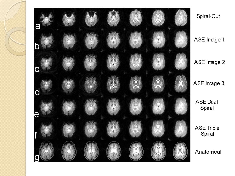
fMRI Results Spiral-Out ASE Image 1 ASE Image 2 ASE Image 3 30s breath-holding task, 5 subjects

22
Percent Signal Change, SNR and CNR

23
Conclusions – ASE spiral Each individual image has reduced apparent geometric distortion and minimal signal loss Although SNR decreases with increasing R 2 - weighting, % signal change increases to compensate ◦ Each image has equivalent CNR Combining images gives higher SNR and has more active voxels Can more optimization be done to further improve SNR and fMRI results?

24
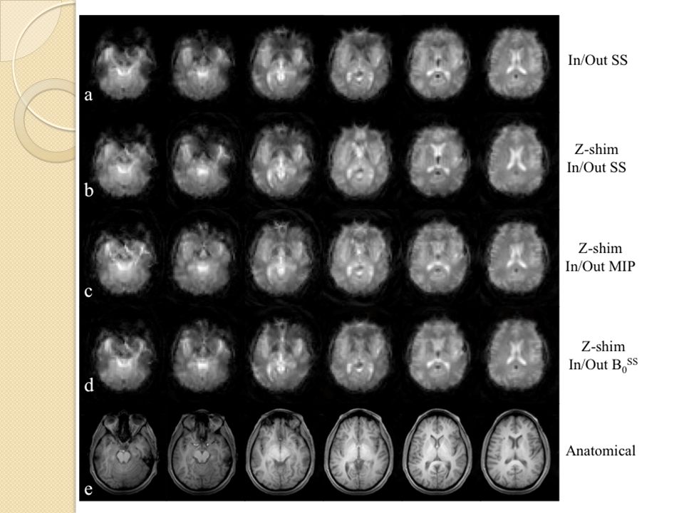
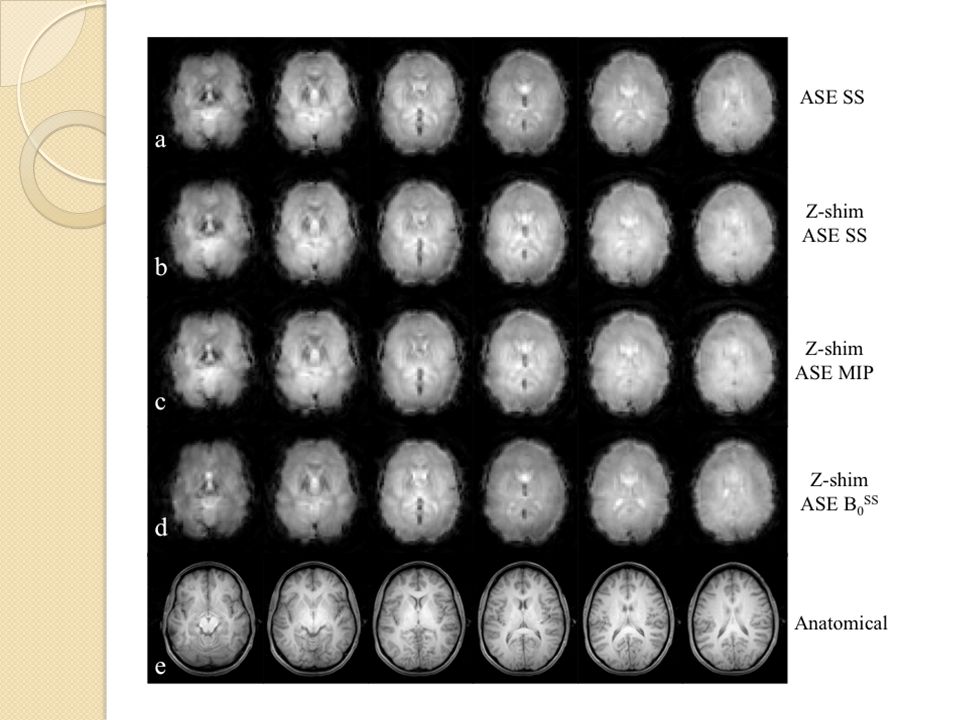
Z-Shim Gradients Z-shim gradients can be used to compensate for SFG gradients oriented along the slice direction (usually the largest voxel dimension) Must acquire at least two images ◦ One with z-shim & one without z-shim Spiral-Out – No Z-Shim Spiral-Out – Z-Shim
 Must acquire at least two images ◦ One with z-shim & one without z-shim Spiral-Out – No Z-Shim Spiral-Out – Z-Shim")
25
Z-shim Asymmetric Spin-Echo Spiral Selection of z-shim values requires automated routine ◦ For 18 slices and three images (10 different z-shim values) – 18000 possible combinations ASE Image 1ASE Image 2 ASE Image 3 ASE Triple spiral
 – possible combinations ASE Image 1ASE Image 2 ASE Image 3 ASE Triple spiral")
26
SNR Results No significant differences! 8 subjects SFG Areas Non-SFG Areas

27
fMRI Results No difference in the amount of active voxels, nor their maximum z-scores 30s breath-holding task, 7 subjects

28
Conclusions – Z-Shim ASE Spiral The B 0 algorithm (summed with SS) gave the best results – not significantly different from the others, or from ASE spiral No significant improvements in SNR or fMRI at group level Z-shim results were highly variable at the individual level ◦ Some individuals had great improvements (30-90%) in SNR, while some saw SNR decreases with the addition of z-shim ◦ May be related to the base field inhomogeneities Not really beneficial to add z-shim to a sequence that is already recovering signal in SFG regions (spiral-in) ASE spiral is already optimized for SFG regions ◦ Z-shim adds unnecessary time and complications with no additional benefits
 gave the best results – not significantly different from the others, or from ASE spiral No significant improvements in SNR or fMRI at group level Z-shim results were highly variable at the individual level ◦ Some individuals had great improvements (30-90%) in SNR, while some saw SNR decreases with the addition of z-shim ◦ May be related to the base field inhomogeneities Not really beneficial to add z-shim to a sequence that is already recovering signal in SFG regions (spiral-in) ASE spiral is already optimized for SFG regions ◦ Z-shim adds unnecessary time and complications with no additional benefits")
29
ASE Spiral & Specificity Spin-echo images are more specific to extravascular sources (i.e. tissue) compared to intravascular sources (i.e. vessels), particularly at high magnetic field strengths ◦ The T 2 of blood at high fields is quite short ◦ At TE > 65 ms (4 T), less than 25% of spin-echo fMRI signal is intravascular Increasing R 2 -weighting in later ASE spiral images may lead to specificity improvements ◦ For most common TE/TE* combinations (ie. 60-70/30 ms), the third image has effective R 2 -weighting that is equivalent to a spin-echo spiral-in at TE = 90-100 ms. Need to determine where ASE spiral activation is located and how it compares to pure gradient-echo and spin-echo sequences
 compared to intravascular sources (i.e. vessels), particularly at high magnetic field strengths ◦ The T 2 of blood at high fields is quite short ◦ At TE > 65 ms (4 T), less than 25% of spin-echo fMRI signal is intravascular Increasing R 2 -weighting in later ASE spiral images may lead to specificity improvements ◦ For most common TE/TE* combinations (ie /30 ms), the third image has effective R 2 -weighting that is equivalent to a spin-echo spiral-in at TE = ms. Need to determine where ASE spiral activation is located and how it compares to pure gradient-echo and spin-echo sequences.")
30
ASE Spiral Specificity Experiment 12 healthy adults (3 males, 9 females) 20 s alternating checkerboard task ◦ Alternating at 8 Hz 4 slices (3 mm) ◦ Slices centred and aligned along calcarine sulcus 2 mm in-plane resolution Sequences: Spiral-in/out, spin-echo spiral-in/out, ASE spiral Venogram (1mm in-plane resolution) – used for delineation of vessels
 20 s alternating checkerboard task ◦ Alternating at 8 Hz 4 slices (3 mm) ◦ Slices centred and aligned along calcarine sulcus 2 mm in-plane resolution Sequences: Spiral-in/out, spin-echo spiral-in/out, ASE spiral Venogram (1mm in-plane resolution) – used for delineation of vessels")
31
FMRI Results

32
Average % Signal Change ( Δ S/S) in Tissue and Vasculature
 in Tissue and Vasculature")
33
Sensitivity vs Specificity The increasing Δ S/S in tissue is promising Later ASE images clearly have elements in common with spin-echo images However, results thus far could be due to later ASE spiral images being less sensitive, not more specific ◦ Need a better metric – Use an individualized specificity analysis Based off of ROC curves, is a function of the false positive rate (FPR) (i.e. the number of false positives – activation on veins, and the number of true negatives – voxels in vessels with no activation) ◦ specificity = 1 – FPR ◦ Generate specificity curves as a function of varying z- thresholds – the faster a curve reaches a value of 1.0 (i.e. no false positives), the more specific the sequence is to tissue compared to vessel
 ◦ specificity = 1 – FPR ◦ Generate specificity curves as a function of varying z- thresholds – the faster a curve reaches a value of 1.0 (i.e. no false positives), the more specific the sequence is to tissue compared to vessel.")
34
Specificity Curve

35
FPR = 50% FPR = 0%

36
Conclusions - Specificity The later ASE spiral images have activation patterns similar to spin-echo images Δ S/S increases with increasing R 2 -weighting in tissue but remains constant in vasculature ◦ Spin-echo images have significantly higher Δ S/S in tissue than in vessel, as do the later ASE images The 2 nd and 3 rd ASE spiral images are more specific than a pure gradient-echo, but less specific than spin-echo The 2 nd ASE image may be the most useful ◦ Has stronger activation (and more active voxels) ◦ The specificity curve is not significantly different than the 3 rd image ◦ Could help improve temporal resolution ◦ May be able to change TE/TE* to improve intravascular suppression
 ◦ The specificity curve is not significantly different than the 3 rd image ◦ Could help improve temporal resolution ◦ May be able to change TE/TE* to improve intravascular suppression")
37
Conclusions Discovered that differences in artifact patterns between spiral-in and spiral-out are due to inter-voxel dephasing ◦ Phase coherence + signal displacement Developed a novel pulse sequence, ASE spiral, that is effective at recovering signal lost in SFG regions while maintaining significant BOLD contrast Determined that z-shim offers no additional benefit to sequences that are already recovering signal in SFG regions ◦ ASE spiral does not benefit from the addition of z-shim Determined that the individual ASE spiral have varying degrees of sensitivity and specificity to fMRI activation ◦ The 2 nd and 3 rd ASE images are more specific to extravascular sources than either spiral-in or spiral-out

38
Future Directions – Current Impact ASE spiral is currently being used to study white matter fMRI ◦ Collaborators have found that ASE spiral is more sensitive to the detection of activation located in white matter (corpus callosum) Increase from 21% to 100% of subjects with activation ◦ Also saw increasing Δ S/S with increasing R 2 -weighting ASE spiral is currently being used for a temporal lobe epilepsy study ◦ Has successfully elicited activation throughout the temporal cortex in several subjects and is insensitive to signal loss around metal clips found in post-surgical patients
 Increase from 21% to 100% of subjects with activation ◦ Also saw increasing Δ S/S with increasing R 2 -weighting ASE spiral is currently being used for a temporal lobe epilepsy study ◦ Has successfully elicited activation throughout the temporal cortex in several subjects and is insensitive to signal loss around metal clips found in post-surgical patients")
39
Future Directions Further spiral-in/spiral-out simulations ◦ Using a realistic head model will give more accurate signal displacement information Comprehensive study is currently be doing to compare ASE spiral and other SFG recovery methods (spiral-in/out & spiral-in/in) to traditional (EPI & spiral) and non-BOLD (spin-echo spiral-in/out and FAIR) fMRI techniques ◦ Uses a task to elicit activation in the temporal lobe ◦ Will determine the effectiveness of signal recovery using a cognitive task Monte Carlo simulations would be useful for modeling the specific contributions (tissue vs vasculature) occurring in both grey and white matter for each of the individual ASE spiral images Also need to investigate different image addition methods ◦ May be able to gain both specificity and sensitivity benefits in post- processing
 to traditional (EPI & spiral) and non-BOLD (spin-echo spiral-in/out and FAIR) fMRI techniques ◦ Uses a task to elicit activation in the temporal lobe ◦ Will determine the effectiveness of signal recovery using a cognitive task Monte Carlo simulations would be useful for modeling the specific contributions (tissue vs vasculature) occurring in both grey and white matter for each of the individual ASE spiral images Also need to investigate different image addition methods ◦ May be able to gain both specificity and sensitivity benefits in post- processing")
40
Acknowlegements Dr. Steven Beyea Dr. Chris Bowen Dr. Ryan D’Arcy Careesa Liu Sujoy Ghosh-Hajra Dr. Martyn Klassen Janet Marshall James Rioux Lindsay Cherpak Tynan Stevens Jodie Gawryluk Erin Mazerolle Connie Adsett Ahmed Elkady Everyone at IBD Atlantic… Walter C. Sumner Foundation

41
Questions?

43
SNR Results

44
fMRI Results

45
ASE Spiral vs Spiral-Out 8 healthy adults (4 males, 4 females) 30 s breath-holding task ◦ 3 subjects were excluded from fMRI results TR = 3 s, 13 slice (5 mm, gap 0.5 mm) 64 x 64 (240 x 240 mm) resolution Spiral-out: TE = 25 ms ASE spiral: TE* = 25 ms, TE = 70 ms Multiple images were combined with equal weighting
 30 s breath-holding task ◦ 3 subjects were excluded from fMRI results TR = 3 s, 13 slice (5 mm, gap 0.5 mm) 64 x 64 (240 x 240 mm) resolution Spiral-out: TE = 25 ms ASE spiral: TE* = 25 ms, TE = 70 ms Multiple images were combined with equal weighting")
46
Z-shim Asymmetric Spin-Echo Spiral Can use unique z-shim gradient (in red) for each individual ASE image
 for each individual ASE image")
47
Z-Shim Automated Routines Prescan-based routines – Optimal combination must have sufficient SNR and large number of recovered voxels 1.MIP-based routine - Images are combined with a maximum intensity projection (MIP) in routine 2.SS-based routine – Images are combined with a sum-of-squares (SS) in routine B 0 field routine – Developed by Truong and Song (2008) ◦ Calculates offsets from an initial field map and calculates the gradients necessary to provide opposing phase twist * Truong et al., Magn Reson Med 59:221-227 (2008)
 in routine 2.SS-based routine – Images are combined with a sum-of-squares (SS) in routine B 0 field routine – Developed by Truong and Song (2008) ◦ Calculates offsets from an initial field map and calculates the gradients necessary to provide opposing phase twist * Truong et al., Magn Reson Med 59: (2008)")
48
Z-Shim ASE Spiral vs ASE Spiral 8 healthy adults (4 males, 4 females) 24 s breath-holding task ◦ 1 subject was excluded from fMRI results TR = 4 s, 18 slice (5 mm, gap 0.5 mm) 64 x 64 (240 x 240 mm) resolution Z-shim ASE spiral & ASE spiral: TE* = 25 ms, TE = 70 ms Images were combined with MIP or SS
 24 s breath-holding task ◦ 1 subject was excluded from fMRI results TR = 4 s, 18 slice (5 mm, gap 0.5 mm) 64 x 64 (240 x 240 mm) resolution Z-shim ASE spiral & ASE spiral: TE* = 25 ms, TE = 70 ms Images were combined with MIP or SS")
50
ASE Spiral Specificity Experiment 12 healthy adults (3 males, 9 females) 20 s alternating checkerboard task ◦ Alternating at 8 Hz TR = 2 s (4-shot), 4 slices (3 mm, gap 0.5 mm) ◦ Slices centred and aligned along calcarine sulcus 128 x 128 (240 x 240 mm) – 1 mm in-plane resolution Spiral-in/out: TE = 30 ms Spin-echo spiral-in/out: TE = 105 ms ASE spiral: TE* = 30 ms, TE = 75 ms Venogram: 256 x 256, TE = 30 ms – used for delineation of vessels
 20 s alternating checkerboard task ◦ Alternating at 8 Hz TR = 2 s (4-shot), 4 slices (3 mm, gap 0.5 mm) ◦ Slices centred and aligned along calcarine sulcus 128 x 128 (240 x 240 mm) – 1 mm in-plane resolution Spiral-in/out: TE = 30 ms Spin-echo spiral-in/out: TE = 105 ms ASE spiral: TE* = 30 ms, TE = 75 ms Venogram: 256 x 256, TE = 30 ms – used for delineation of vessels")
Similar presentations


>")


 quantum property of protons energy absorbed when precession frequency matches radio frequency.>")


