Download presentation
Presentation is loading. Please wait.

1
Lecture 4 (Chapter 13 in Perkins) Crystal Chemistry Part 3: Coordination of Ions Pauling’s Rules Crystal Structures The packing animations below are due to John Winter, click here Get polyhedral models from cabinet
 Crystal Chemistry Part 3: Coordination of Ions Pauling’s Rules Crystal Structures The packing animations below are due to John Winter, click here Get polyhedral models from cabinet")
2
Coordination of Ions For ionic bonding, ion geometry ~ spherical For ionic bonding, ion geometry ~ spherical Spherical ions will geometrically pack (coordinate) oppositely charged ions around them as tightly as possible while maintaining charge neutrality Spherical ions will geometrically pack (coordinate) oppositely charged ions around them as tightly as possible while maintaining charge neutrality For a particular ion, the surrounding coordination ions define the apices (corners) of a polyhedron For a particular ion, the surrounding coordination ions define the apices (corners) of a polyhedron The number of surrounding ions is the Coordination Number The number of surrounding ions is the Coordination Number
 oppositely charged ions around them as tightly as possible while maintaining charge neutrality Spherical ions will geometrically pack (coordinate) oppositely charged ions around them as tightly as possible while maintaining charge neutrality For a particular ion, the surrounding coordination ions define the apices (corners) of a polyhedron For a particular ion, the surrounding coordination ions define the apices (corners) of a polyhedron The number of surrounding ions is the Coordination Number The number of surrounding ions is the Coordination Number")
3
Ionic Compound Formation Anions – negatively charged –Larger than the un-ionized atom Cations – positively charged Smaller than the un-ionized atom Attraction »Anion – Cation Repulsion »Anion – Anion »Cation – Cation - + -- ++

4
Coordination Number and Radius Ratio Radius Ratio is Rc (cation) / Ra (anion) See also the Ionic Radii table of Perkins, following the inside front cover from K&D Modified from K&D See Figure 13.3 of Perkins
 / Ra (anion) See also the Ionic Radii table of Perkins, following the inside front cover from K&D Modified from K&D See Figure 13.3 of Perkins")
5
Atomic and Ionic Radii Can't absolutely determine: e - cloud is nebulous & based on probability of encountering an e -. In crystalline solids the center-to-center distance = bond length & is accepted to = sum of ionic radii How get ionic radius of X & Y in XY compound??

6
Atomic and Ionic Radii Pure element first Native Cu. Atomic radius = 1/2 bond length a a X-ray d 100 a Ionic radius = 2 4 2 a

7
Absolute radius of an atom based on location of the maximum density of outermost electron shell Absolute radius of an atom based on location of the maximum density of outermost electron shell Effective radius dependent on the charge, type, size, and number of neighboring atoms/ions Effective radius dependent on the charge, type, size, and number of neighboring atoms/ions - in bonds between identical atoms, this is half the interatomic distance - in bonds between different ions, the distance between the ions is controlled by the attractive and repulsive force between the two ions and their charges Atomic Radii

8
Charge and Attractive Force Control on Effective Ionic Radii Approach until Repulsive and Attractive Forces the same

9
Effect of Coordination Number and Valence on Effective Ionic Radius Increasing Ionic radii Decreasing Ionic radii Higher coordination numbers have larger effective ionic radius Extreme valence shells (1,6,7) have larger effective ionic radius
 have larger effective ionic radius")
10
Coordination Number (CN) (# of nearest neighbors) vs. ionic radius. For cations of one element, higher coordination numbers have larger effective ionic radius

11
Coordination with O -2 Anions Note: Sulfur can have CN 6 at great depths For example, in the inner core

12
When Rc / Ra approaches 1 a “close packed” array forms

13
We always consider coordination of anions about a central cation We always consider coordination of anions about a central cation Coordination Polyhedra Halite Cl Cl Cl Cl Na

14
Can predict the coordination Can predict the coordination by considering the radius ratio: by considering the radius ratio: R C /R A Cations are generally smaller than anions so begin with maximum ratio = 1.0 Coordination Polyhedra

15
Radius Ratio: R C /R A = 1.0 (commonly native elements) Equal sized spheres “Closest Packed” Notice:6 nearest neighbors in the plane arranged in a hexagon Note dimples in which next layer atoms will settle Two dimple types: Type 1 upper point NE Type 1 upper point NE Type 2 upper point NW Type 2 upper point NW They are equivalent since you could rotate the whole structure 60 o and exchange them 1 2
 Equal sized spheres Closest Packed Notice:6 nearest neighbors in the plane arranged in a hexagon Note dimples in which next layer atoms will settle Two dimple types: Type 1 upper point NE Type 1 upper point NE Type 2 upper point NW Type 2 upper point NW They are equivalent since you could rotate the whole structure 60 o and exchange them 1 2")
16
Closest Packing Add next layer (red) Once first red atom settles in, can only fill other dimples of that type In this case covered all type 2 dimples, only 1’s are left 1
 Once first red atom settles in, can only fill other dimples of that type In this case covered all type 2 dimples, only 1’s are left 1")
17
Closest Packing Third layer ? Third layer dimples again 2 types Call layer 1 A sites Layer 2 = B sites (no matter which choice of dimples is occupied) Layer 3 can now occupy A-type site (directly above yellow atoms) or C-type site (above voids in both A and B layers) A C
 Layer 3 can now occupy A-type site (directly above yellow atoms) or C-type site (above voids in both A and B layers) A C.")
18
Closest Packing Third layer: If occupy A-type site the layer ordering becomes A-B-A-B and creates a hexagonal closest packed structure (HCP) Coordination number (nearest or touching neighbors) = 12 6 coplanar 3 above the plane 3 below the plane
 Coordination number (nearest or touching neighbors) = 12 6 coplanar 3 above the plane 3 below the plane")
19
Closest Packing Third layer: If occupy A-type site the layer ordering becomes A-B-A-B and creates a hexagonal closest packed structure (HCP)
")
20
Closest Packing Third layer: If occupy A-type site the layer ordering becomes A-B-A-B and creates a hexagonal closest packed structure (HCP)
")
21
Closest Packing Third layer: If occupy A-type site the layer ordering becomes A-B-A-B and creates a hexagonal closest packed structure (HCP)
")
22
Closest Packing Third layer: If occupy A-type site the layer ordering becomes A-B-A-B and creates a hexagonal closest packed structure (HCP) Note top layer atoms are directly above bottom layer atoms
 Note top layer atoms are directly above bottom layer atoms")
23
Closest Packing Third layer: Unit cell

24
Closest Packing Third layer: Unit cell

25
Closest Packing Third layer: Unit cell

26
Closest Packing Third layer: View from top shows hexagonal unit cell (HCP)
")
27
Closest Packing Third layer: View from top shows hexagonal unit cell (HCP)
")
28
Closest Packing Alternatively we could place the third layer in the C-type site (above voids in both A and B layers) C
 C")
29
Closest Packing Third layer: If occupy C-type site the layer ordering is A-B-C-A-B-C and creates a cubic closest packed structure (CCP) Blue layer atoms are now in a unique position above voids between atoms in layers A and B
 Blue layer atoms are now in a unique position above voids between atoms in layers A and B")
30
Closest Packing Third layer: If occupy C-type site the layer ordering is A-B-C-A-B-C and creates a cubic closest packed structure (CCP) Blue layer atoms are now in a unique position above voids between atoms in layers A and B
 Blue layer atoms are now in a unique position above voids between atoms in layers A and B")
31
Closest Packing Third layer: If occupy C-type site the layer ordering is A-B-C-A-B-C and creates a cubic closest packed structure (CCP) Blue layer atoms are now in a unique position above voids between atoms in layers A and B
 Blue layer atoms are now in a unique position above voids between atoms in layers A and B")
32
Closest Packing Third layer: If occupy C-type site the layer ordering is A-B-C-A-B-C and creates a cubic closest packed structure (CCP) Blue layer atoms are now in a unique position above voids between atoms in layers A and B
 Blue layer atoms are now in a unique position above voids between atoms in layers A and B")
33
Closest Packing Third layer: If occupy C-type site the layer ordering is A-B-C-A-B-C and creates a cubic closest packed structure (CCP) Blue layer atoms are now in a unique position above voids between atoms in layers A and B
 Blue layer atoms are now in a unique position above voids between atoms in layers A and B")
34
Cubic Closest Packing View from the same side shows the cubic close packing (CCP), also called face-centered cubic (FCC) because of the unit cell that results. Notice that every face of the cube has an atom at every face center. (CCP), also called face-centered cubic (FCC) because of the unit cell that results. Notice that every face of the cube has an atom at every face center. The atoms are slightly shrunken to aid in visualizing the structure A-layer B-layer C-layer A-layer
, also called face-centered cubic (FCC) because of the unit cell that results. Notice that every face of the cube has an atom at every face center. The atoms are slightly shrunken to aid in visualizing the structure A-layer B-layer C-layer A-layer.")
35
Closest Packing Rotating toward a top view

36
Closest Packing Rotating toward a top view

37
Closest Packing You are looking at a top yellow layer A with a blue layer C below, then a red layer B and a yellow layer A again at the bottom

38
What happens when R C /R A decreases? The center cation becomes too small for the C.N.=12 site (as if a hard-sphere atom model began to rattle in the 12 site) and it drops to the next lower coordination number (next smaller site). It will do this even if it is slightly too large for the next lower site. It is as though it is better to fit a slightly large cation into a smaller site than to have one rattle about in a site that is too large.
 and it drops to the next lower coordination number (next smaller site). It will do this even if it is slightly too large for the next lower site. It is as though it is better to fit a slightly large cation into a smaller site than to have one rattle about in a site that is too large..")
39
Body-Centered Cubic (BCC) with cation (red) in the center of a cube Coordination number is now 8 (corners of cube) The next smaller crystal site is the CUBE:
 with cation (red) in the center of a cube Coordination number is now 8 (corners of cube) The next smaller crystal site is the CUBE:")
40
Then a hard-sphere cation would “rattle” in the position, and it would shift to the next lower coordination (next smaller site). What is the R C /R A of that limiting condition?? A central cation will remain in 8 coordination with decreasing R C /R A until it again reaches the limiting situation in which all atoms mutually touch. Set = 1 Diagonal length then = 2 arbitrary since will deal with ratios

41
Then a hard-sphere cation would “rattle” in the position, and it would shift to the next lower coordination (next smaller site). What is the R C /R A of that limiting condition?? A central cation will remain in 8 coordination with decreasing R C /R A until it again reaches the limiting situation in which all atoms mutually touch. Rotate

42
Then a hard-sphere cation would “rattle” in the position, and it would shift to the next lower coordination (next smaller site). What is the R C /R A of that limiting condition?? A central cation will remain in 8 coordination with decreasing R C /R A until it again reaches the limiting situation in which all atoms mutually touch. Rotate

43
Then a hard-sphere cation would “rattle” in the position, and it would shift to the next lower coordination (next smaller site). What is the R C /R A of that limiting condition?? A central cation will remain in 8 coordination with decreasing R C /R A until it again reaches the limiting situation in which all atoms mutually touch. Rotate

44
Then a hard-sphere cation would “rattle” in the position, and it would shift to the next lower coordination (next smaller site). What is the R C /R A of that limiting condition?? A central cation will remain in 8 coordination with decreasing R C /R A until it again reaches the limiting situation in which all atoms mutually touch. Rotate

45
Then a hard-sphere cation would “rattle” in the position, and it would shift to the next lower coordination (next smaller site). What is the R C /R A of that limiting condition?? A central cation will remain in 8 coordination with decreasing R C /R A until it again reaches the limiting situation in which all atoms mutually touch. Rotate

46
Then a hard-sphere cation would “rattle” in the position, and it would shift to the next lower coordination (next smaller site). What is the R C /R A of that limiting condition?? A central cation will remain in 8 coordination with decreasing R C /R A until it again reaches the limiting situation in which all atoms mutually touch. Rotate

47
Then a hard-sphere cation would “rattle” in the position, and it would shift to the next lower coordination (next smaller site). What is the R C /R A of that limiting condition?? A central cation will remain in 8 coordination with decreasing R C /R A until it again reaches the limiting situation in which all atoms mutually touch. Rotate

48
What is the R C /R A of that limiting condition?? 1.732 = d C + d A If d A = 1 then d C = 0.732 then d C = 0.732 d C /d A = R C /R A = 0.732/1 = 0.732 = 0.732/1 = 0.732 A central cation will remain in 8 coordination with decreasing R C /R A until it again reaches the limiting situation in which all atoms mutually touch. Central Plane

49
The limits for 8 coordination are thus between 1.0 (when it would be CCP or HCP) and 0.732 Note: Body Centered Cubic is not a closest-packed oxygen arrangement.
 and Note: Body Centered Cubic is not a closest-packed oxygen arrangement.")
50
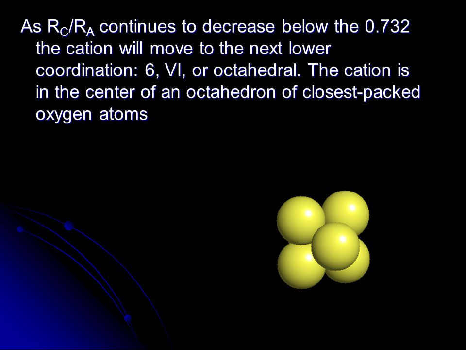
As R C /R A continues to decrease below the 0.732 the cation will move to the next lower coordination: 6, VI, or octahedral. The cation is in the center of an octahedron of closest-packed oxygen atoms

55
As R C /R A continues to decrease below the 0.732 the cation will move to the next lower coordination: VI, or octahedral. The cation is in the center of an octahedron of closest-packed oxygen atoms What is the R C /R A of that limiting condition?? 1.414 = d C + d A If d A = 1 then d C = 0.414 then d C = 0.414 d C /d A = R C /R A = 0.414/1 = 0.414 = 0.414/1 = 0.414

56
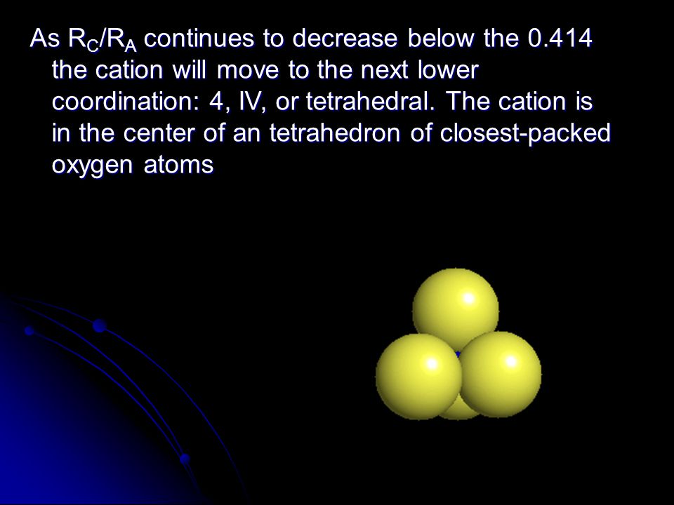
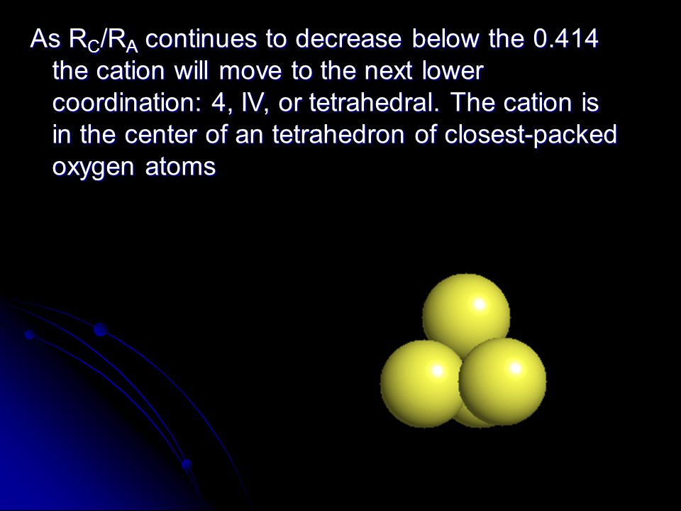
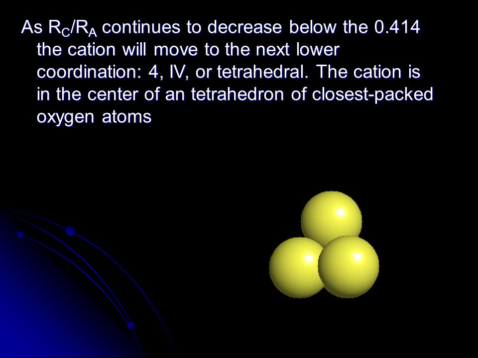
As R C /R A continues to decrease below the 0.414 the cation will move to the next lower coordination: 4, IV, or tetrahedral. The cation is in the center of an tetrahedron of closest-packed oxygen atoms

63
As R C /R A continues to decrease below the 0.414 the cation will move to the next lower coordination: IV, or tetrahedral. The cation is in the center of an tetrahedron of closest-packed oxygen atoms What is the R C /R A of the limiting condition?? Center-to-corner distance of a tetrahedron with edges of 1.0 = 0.6124 R C = 0.6124 - 0.5 = 0.1124 R C /R A = 0.1124/0.5 = 0.225 = 0.1124/0.5 = 0.225 See derivation fig 4.3 c page 70

64
As R C /R A continues to decrease below the 0.22 the cation will move to the next lower coordination: III. The cation moves from the center of the tetrahedron to the center of an coplanar tetrahedral face of 3 oxygen atoms What is the R C /R A of the limiting condition?? cos 60 = 0.5/y y = 0.5774 R C = 0.5774 - 0.5 = 0.0774 R C /R A = 0.0774/0.5 = 0.155 = 0.0774/0.5 = 0.155

65
If R C /R A decreases below 0.15 the cation will move to the next lower coordination: 2 or II. The cation moves directly between 2 neighboring oxygen atoms

67
Pauling’s Rules Rule 1: A coordination polyhedron of anions is formed around each cation, where: - the cation-anion distance is determined by the sum of the ionic radii, and - the coordination number of the polyhedron is determined by the cation/anion radius ratio (Rc:Ra) Linus Pauling
 Linus Pauling")
68
Rule 2: The electrostatic valency principle The strength of an ionic (electrostatic) bond (electrostatic valency e.v.) between a cation and an anion is equal to the charge of the ion (z) divided by its coordination number (n): e.v. = z/n e.v. = z/n In a stable (neutral) structure, a charge balance results between the cation and its polyhedral anions with which it is bonded. Pauling’s Rules
 structure, a charge balance results between the cation and its polyhedral anions with which it is bonded. Pauling’s Rules.")
69
Charge Balance in Halite In Halite, Na + has CN 6 and valence +1 Interpretation: Each Na + has 6 Cl - neighbors, so each Cl- contributes a charge of -1/6 to the Na + 6 x -1/6 = -1, so a charge balance results between the Na+ cation and the six polyhedral Cl- anions with which it bonded. NEUTRALITY IS ACHIEVED

70
Charge Balance In Fluorite Fluorite In Fluorite, Ca ++ has CN 8 and valence +2, so the electrostatic valency is ¼ e.v. Interpretation: Each Ca ++ has 8 F - neighbors, so each F- contributes a charge of -1/4 to the Ca ++ 8 x -1/4 = -2, so a charge balance results between the Ca ++ cation and the eight polyhedral F- anions with which it bonded. NEUTRALITY IS ACHIEVED

71
Formation of Anionic Groups Carbonate Sulfate C has valence +4 C.N = 3 e.v. = 4/3 = 1 1/3 S has valence +6 CN = 4 electrostatic valency = 6/4 = 1 1/2 Remaining charge on Oxygens available for bonding e- for Carbon 2.5, for O 3.5 covalent e- S 2.4 so also covalent If electronegativity of anion and cation differs by 2.0 or more will be ionic

72
Rule 3: Sharing of faces or edges is unstable. Rule 3: Sharing of faces or edges is unstable. Rule 4: In structures with different types of cations, those cations with high valency and small CN tend not to share polyhedra with each other; when they do, polyhedra are deformed to accommodate cation repulsion Rule 4: In structures with different types of cations, those cations with high valency and small CN tend not to share polyhedra with each other; when they do, polyhedra are deformed to accommodate cation repulsion Pauling’s Rules C.N. = “coordination number”

73
The number and types of different structural sites tends to be limited, even in complex minerals. The number and types of different structural sites tends to be limited, even in complex minerals. Comment: Different ionic elements are forced to occupy the same structural positions. This leads to solid solution. Pauling’s Rules - principle of parsimony

74
Ionic Compound Formation Stable ionic crystals: Stable ionic crystals: maximize cation-anion contact maximize cation-anion contact minimize anion-anion & cation-cation contact minimize anion-anion & cation-cation contact 2-dimensional illustration of the concept of stability:

75
Visualizing Crystal Structure Ball and Stick Model Polyhedra Model Beryl - Be 3 Al 2 (Si 6 O 18 ) 4-O Tetrahedral (T) and 6-O Octahedral (O)Show polyhedral models Gold colored spheres cations
 4-O Tetrahedral (T) and 6-O Octahedral (O)Show polyhedral models Gold colored spheres cations")
76
Isostructural Types AX Compounds – Halite (NaCl) structure AX Compounds – Halite (NaCl) structure Anions – in Cubic Close Packing Cations – in octahedral sites Rc/Ra =.73-.41 so CN = 6 Examples: Halides: +1 cations (Li, Na, K, Rb) w/ anion charge -1: anions (F, Cl, Br, I) Oxides: +2 cations (Mg, Ca, Sr, Ba, Ni) w/ O -2 Sulfides: +2 cations (Zn, Pb) w/ S -2
 structure AX Compounds – Halite (NaCl) structure Anions – in Cubic Close Packing Cations – in octahedral sites Rc/Ra = so CN = 6 Examples: Halides: +1 cations (Li, Na, K, Rb) w/ anion charge -1: anions (F, Cl, Br, I) Oxides: +2 cations (Mg, Ca, Sr, Ba, Ni) w/ O -2 Sulfides: +2 cations (Zn, Pb) w/ S -2")
77
Isostructural Types CCP= FCC close packing of the anions, small cations in octohedral “holes”

78
Isostructural Types AX Compounds – Sphalerite (ZnS) structure AX Compounds – Sphalerite (ZnS) structure R Zn /R S =0.60/1.84=0.32 (tetrahedral)
 structure AX Compounds – Sphalerite (ZnS) structure R Zn /R S =0.60/1.84=0.32 (tetrahedral)")
79
AX 2 Compounds – Fluorite (CaF 2 ) structure AX 2 Compounds – Fluorite (CaF 2 ) structure Example CaF 2 : R Ca / R F = 1.12 / 1.31 = 0.75 (cubic CN = 8) Examples: some Halides (CaF 2, BaCl 2...); Oxides (ZrO 2...) Isostructural Types
 structure AX 2 Compounds – Fluorite (CaF 2 ) structure Example CaF 2 : R Ca / R F = 1.12 / 1.31 = 0.75 (cubic CN = 8) Examples: some Halides (CaF 2, BaCl 2...); Oxides (ZrO 2...) Isostructural Types")
80
ABO 4 Compounds – Spinel (MgAl 2 O 4 )structure ABO 4 Compounds – Spinel (MgAl 2 O 4 )structure - Oxygen anions in CCP array - Two different cations (may be same element w two different valences) in tetrahedral (T) sites (e.g. Mg 2+, Fe 2+, Mn 2+, Zn 2+ ) or octahedral (O) sites (e.g. Al 3+, Cr 3+, Fe 3+ ) or octahedral (O) sites (e.g. Al 3+, Cr 3+, Fe 3+ ) Isostructural Types – O and T sites
 or octahedral (O) sites (e.g. Al 3+, Cr 3+, Fe 3+ ) or octahedral (O) sites (e.g. Al 3+, Cr 3+, Fe 3+ ) Isostructural Types – O and T sites.")
81
Nesosilicates Sorosilicates Cyclosilicates Inosilicates (single chain) Inosilicates (double chain) Phyllosilicates Tectosilicates Quartz group, Feldspars Feldspathoids Zeolites Olivine, Zircon Staurolite Epidote Beryl Tourmaline Pyroxenes Amphiboles Micas, clays Serpentine Chlorite
 Inosilicates (double chain) Phyllosilicates Tectosilicates Quartz group, Feldspars Feldspathoids Zeolites Olivine, Zircon Staurolite Epidote Beryl Tourmaline Pyroxenes Amphiboles Micas, clays Serpentine Chlorite")
82
Next time Crystal Chemistry IV Crystal Chemistry IV Compositional Variation of Minerals Solid Solution Mineral Formula Calculations Graphical Representation of Mineral Compositions

Similar presentations


 Crystal Chemistry Part 3: Coordination of Ions Pauling’s Rules Crystal Structures.>")


 Camosun College.>")


 Fixed, immobile (so to speak) Symmetry Symmetry Crystals Crystals So what’s the inner order? So what’s.>")


